light FORD C MAX 2011 2.G Service Manual
[x] Cancel search | Manufacturer: FORD, Model Year: 2011, Model line: C MAX, Model: FORD C MAX 2011 2.GPages: 296, PDF Size: 7.87 MB
Page 146 of 296
Downloaded from www.Manualslib.com manuals search engine PRINCIPLE OF OPERATION
Note:
Depending on applicable laws and
regulations in the country for which your
vehicle was originally built, the brake lamps
may flash if you brake heavily.
Note: Occasional brake noise is normal and
often does not indicate a concern. In normal
operation, the system may emit occasional
or intermittent squeal or groan noises when
the brakes are applied. Such noises are
usually caused by environmental conditions
such as cold, heat, moisture, road dust, salt
or mud.
Disc brakes
Wet brake discs result in reduced braking
efficiency. Dab the brake pedal when
driving from a car wash to remove the film
of water.
ABS WARNING
The ABS does not relieve you of your
responsibility to drive with due care
and attention.
The ABS helps you to maintain full steering
and directional stability when you brake
heavily in an emergency, by preventing the
road wheels from locking.
HINTS ON DRIVING WITH
ANTI-LOCK BRAKES
When the ABS is operating, the brake pedal
will pulse. This is normal. Maintain pressure
on the brake pedal.
The ABS will not eliminate the dangers
inherent when:
•
you drive too close to the vehicle in
front of you.
• the vehicle is aquaplaning. •
you take corners too fast.
• the road surface is poor.
PARKING BRAKE WARNING
Vehicles with an automatic
transmission should always be left
with the selector lever in position P
(Park). •
Press the foot brake pedal firmly.
• Pull the parking brake lever up smartly
to its fullest extent.
• Do not press the release button while
pulling the lever up.
• If your vehicle is parked on a hill and
facing uphill, select first gear or P
(Park) and turn the steering wheel
away from the kerb.
• If your vehicle is parked on a hill and
facing downhill, select reverse gear or
P (Park) and turn the steering wheel
towards the kerb.
To release the parking brake, press the
brake pedal firmly, pull the lever up slightly,
depress the release button and push the
lever down.
144
Brakes
Page 148 of 296
Downloaded from www.Manualslib.com manuals search engine PRINCIPLE OF OPERATION
The system makes it easier to pull away
when the vehicle is on a slope without the
need to use the parking brake.
When the system is active, the vehicle will
remain stationary on the slope for a short
time after you release the brake pedal.
During this time, you have time to move
your foot from the brake to the accelerator
pedal and pull away. The brakes are
released automatically once the engine
has developed sufficient drive to prevent
the vehicle from rolling down the slope.
This is an advantage when pulling away
on a slope, for example from a car park
ramp, traffic lights or when reversing uphill
into a parking space.
WARNING
The system does not replace the
parking brake. When you leave the
vehicle, always apply the parking
brake and select first or reverse gear. USING HILL START ASSIST
The system is activated automatically
when you stop your vehicle on a slope
greater than 3%. The system operates with
the vehicle facing downhill if reverse gear
is selected and with the vehicle facing
uphill if any forward gear is selected.
Vehicles with manual
transmission only
The system can be switched on and off
using the information display. See General
Information (page 83).
Activating the system
WARNINGS
You must remain in the vehicle once
you have activated the system. WARNINGS
At all times you are responsible for
controlling the vehicle, supervising
the system and intervening, if
required. If a malfunction is detected when the
system is active, the system will be
deactivated and a message will be
shown in the display. See Information
Messages (page 90). You can activate the system only if the
following conditions have been met:
•
The engine is running.
• The system is switched on.
• On vehicles with manual transmission,
the clutch pedal is pressed.
• No failure mode is present.
To activate the system:
1. Press the brake pedal to bring the vehicle to a complete standstill. Keep
the brake pedal depressed.
2. If the sensors detect that the vehicle is
on a slope the system will be activated
automatically.
3. When you remove your foot from the brake pedal, the vehicle will remain on
the slope without rolling away for a
short time. This hold time will
automatically be extended if you are
in the process of driving off.
4. Drive off in the normal manner. The brakes will be released automatically.
Deactivating the system
To deactivate the system, perform one of
the following:
146
Hill Start Assist
Page 150 of 296
Downloaded from www.Manualslib.com manuals search engine PRINCIPLE OF OPERATION
WARNING
The system does not relieve you of
your responsibility to drive with due
care and attention.
CAUTIONS
Vehicles fitted with a trailer tow
module not approved by us may not
correctly detect obstacles.
The sensors may not detect objects
in heavy rain or other conditions that
cause disruptive reflections.
The sensors may not detect objects
with surfaces that absorb ultrasonic
waves.
The parking aid does not detect
obstacles moving away from the
vehicle. They will only be detected
shortly after they start to move towards
the vehicle again. If you use a high pressure spray to
wash your vehicle, only spray the
sensors briefly from a distance not
less than 20 centimetres (8 inches). Parking aid sends tones via the audio
system fitted and approved by us. If
this is not working the parking aid
system will not work. Note:
On vehicles fitted with a tow ball
arm, the rear parking aid is deactivated
automatically when any trailer lamps (or
lighting boards) are connected to the 13-pin
socket via a trailer tow module we have
approved.
Note: Keep the sensors free from dirt, ice
and snow. Do not clean with sharp objects.
Note: The parking aid may emit false tones
if it detects a signal using the same
frequency as the sensors or if the vehicle is
fully laden. Note:
The outer sensors may detect the
side walls of a garage. If the distance
between the outer sensor and the side wall
remains constant for three seconds, the
tone will switch off. As you continue, the
inner sensors will detect rearward objects.
USING THE PARKING AID -
VEHICLES WITH: REAR
PARKING AID WARNING
The parking aid does not relieve you
of your responsibility to drive with
due care and attention.
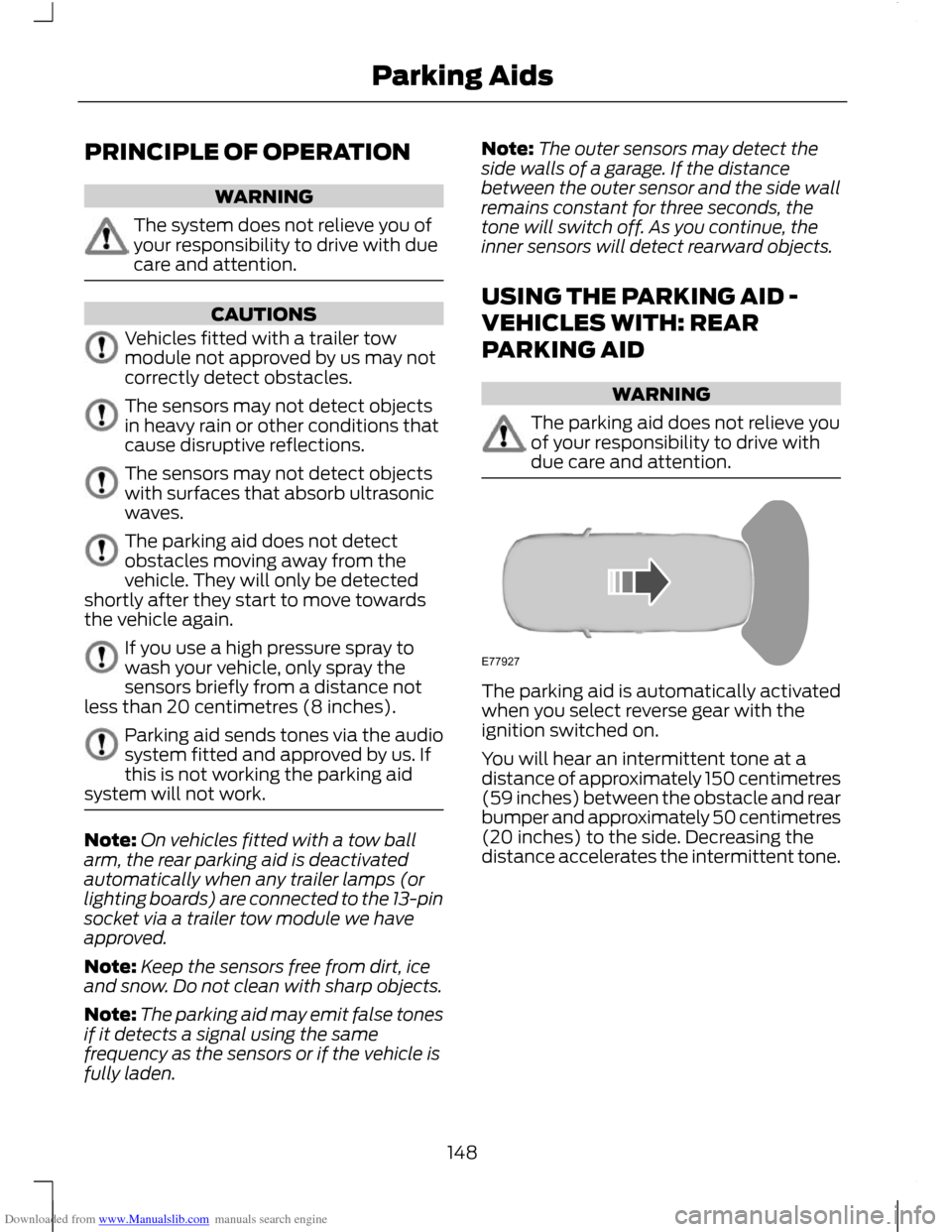
The parking aid is automatically activated
when you select reverse gear with the
ignition switched on.
You will hear an intermittent tone at a
distance of approximately 150 centimetres
(59 inches) between the obstacle and rear
bumper and approximately 50 centimetres
(20 inches) to the side. Decreasing the
distance accelerates the intermittent tone.
148
Parking AidsE77927
Page 151 of 296
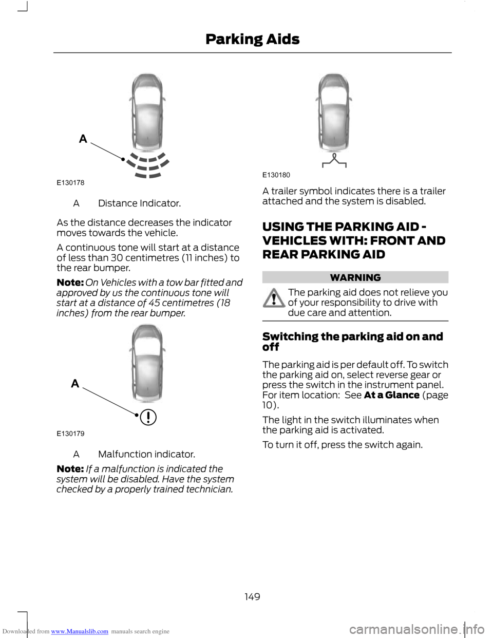
Downloaded from www.Manualslib.com manuals search engine Distance Indicator.
A
As the distance decreases the indicator
moves towards the vehicle.
A continuous tone will start at a distance
of less than 30 centimetres (11 inches) to
the rear bumper.
Note: On Vehicles with a tow bar fitted and
approved by us the continuous tone will
start at a distance of 45 centimetres (18
inches) from the rear bumper. Malfunction indicator.
A
Note: If a malfunction is indicated the
system will be disabled. Have the system
checked by a properly trained technician. A trailer symbol indicates there is a trailer
attached and the system is disabled.
USING THE PARKING AID -
VEHICLES WITH: FRONT AND
REAR PARKING AID
WARNING
The parking aid does not relieve you
of your responsibility to drive with
due care and attention.
Switching the parking aid on and
off
The parking aid is per default off. To switch
the parking aid on, select reverse gear or
press the switch in the instrument panel.
For item location: See At a Glance (page
10).
The light in the switch illuminates when
the parking aid is activated.
To turn it off, press the switch again.
149
Parking AidsE130178A E130179A E130180
Page 157 of 296
Downloaded from www.Manualslib.com manuals search engine PRINCIPLE OF OPERATION
The camera is a visual aid for use when
reversing.
WARNING
The system does not relieve you of
your responsibility to drive with due
care and attention.
CAUTIONS
If you use a high pressure spray to
wash your vehicle, only spray the
camera briefly from a distance not
less than 20 centimetres (8 inches). Do not apply pressure to the camera.
Note:
Keep the camera free from dirt, ice
and snow. Do not clean with sharp objects,
degreaser, wax or organic products. Use only
a soft cloth.
During operation, guide lines appear in the
display which represent your vehicle's path
and approximate distance from rearward
objects.
USING THE REAR VIEW
CAMERA WARNINGS
The operation of the camera may
vary depending on the ambient
temperature, vehicle and road
conditions. The distances shown in the display
may differ from the actual distance.
Do not place objects in front of the
camera.
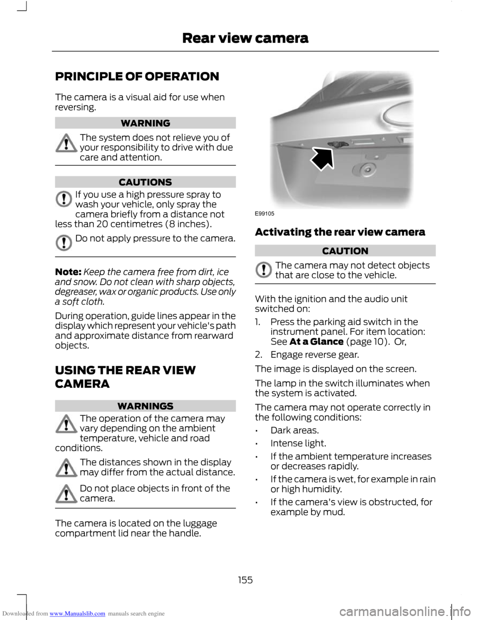
The camera is located on the luggage
compartment lid near the handle. Activating the rear view camera
CAUTION
The camera may not detect objects
that are close to the vehicle.
With the ignition and the audio unit
switched on:
1. Press the parking aid switch in the
instrument panel. For item location:
See At a Glance (page 10). Or,
2. Engage reverse gear.
The image is displayed on the screen.
The lamp in the switch illuminates when
the system is activated.
The camera may not operate correctly in
the following conditions:
• Dark areas.
• Intense light.
• If the ambient temperature increases
or decreases rapidly.
• If the camera is wet, for example in rain
or high humidity.
• If the camera's view is obstructed, for
example by mud.
155
Rear view cameraE99105
Page 174 of 296
Downloaded from www.Manualslib.com manuals search engine RUNNING-IN
Tyres
WARNING
New tyres need to be run-in for
approximately 500 kilometres (300
miles). During this time, you may
experience different driving characteristics. Brakes and clutch
WARNING
Avoid heavy use of the brakes and
clutch if possible for the first 150
kilometres (100 miles) in town and
for the first 1500 kilometres (1000 miles)
on motorways. Engine
CAUTION
Avoid driving too fast during the first
1500 kilometres (1000 miles). Vary
your speed frequently and change up
through the gears early. Do not labour the
engine. COLD WEATHER
PRECAUTIONS
The functional operation of some
components and systems can be affected
at temperatures below -30°C (-22°F).
DRIVING THROUGH WATER
Driving through water
CAUTIONS
Drive through water in an emergency
only, and not as part of normal driving.
Engine damage can occur if water
enters the air filter. In an emergency, the vehicle can be driven
through water to a maximum depth of 200
millimetres (8 inches) and at a maximum
speed of 10 km/h (6 mph). Extra caution
should be exercised when driving through
flowing water.
When driving in water, maintain a low
speed and do not stop the vehicle. After
driving through water, and as soon as it is
safe to do so:
•
Depress the brake pedal lightly and
check that full brake function is
achieved.
• Check that the horn works.
• Check that the vehicle's lights are fully
operational.
• Check the power assistance
of the steering system.
172
Driving Hints
Page 178 of 296
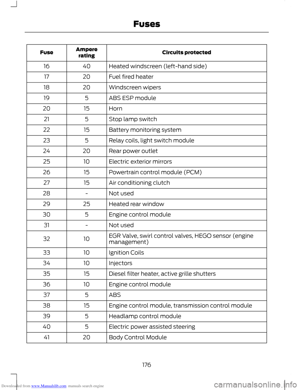
Downloaded from www.Manualslib.com manuals search engine Circuits protected
Ampere
rating
Fuse
Heated windscreen (left-hand side)
40
16
Fuel fired heater
20
17
Windscreen wipers
20
18
ABS ESP module
5
19
Horn
15
20
Stop lamp switch
5
21
Battery monitoring system
15
22
Relay coils, light switch module
5
23
Rear power outlet
20
24
Electric exterior mirrors
10
25
Powertrain control module (PCM)
15
26
Air conditioning clutch
15
27
Not used
-
28
Heated rear window
25
29
Engine control module
5
30
Not used
-
31
EGR Valve, swirl control valves, HEGO sensor (engine
management)
10
32
Ignition Coils
10
33
Injectors
10
34
Diesel filter heater, active grille shutters
15
35
Engine control module
10
36
ABS
5
37
Engine control module, transmission control module
15
38
Headlamp control module
5
39
Electric power assisted steering
5
40
Body Control Module
20
41
176
Fuses
Page 181 of 296
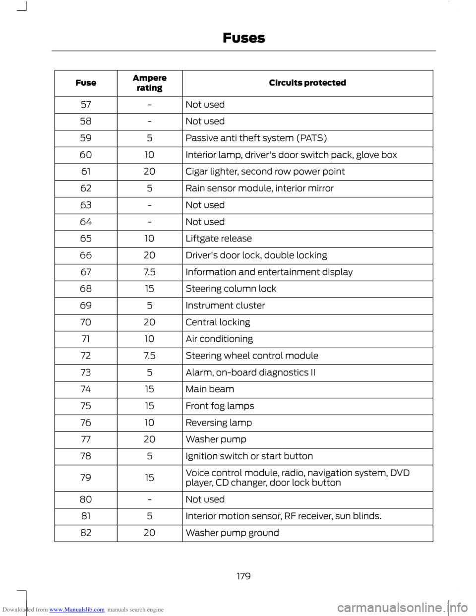
Downloaded from www.Manualslib.com manuals search engine Circuits protected
Ampere
rating
Fuse
Not used
-
57
Not used
-
58
Passive anti theft system (PATS)
5
59
Interior lamp, driver's door switch pack, glove box
10
60
Cigar lighter, second row power point
20
61
Rain sensor module, interior mirror
5
62
Not used
-
63
Not used
-
64
Liftgate release
10
65
Driver's door lock, double locking
20
66
Information and entertainment display
7.5
67
Steering column lock
15
68
Instrument cluster
5
69
Central locking
20
70
Air conditioning
10
71
Steering wheel control module
7.5
72
Alarm, on-board diagnostics II
5
73
Main beam
15
74
Front fog lamps
15
75
Reversing lamp
10
76
Washer pump
20
77
Ignition switch or start button
5
78
Voice control module, radio, navigation system, DVD
player, CD changer, door lock button
15
79
Not used
-
80
Interior motion sensor, RF receiver, sun blinds.
5
81
Washer pump ground
20
82
179
Fuses
Page 208 of 296
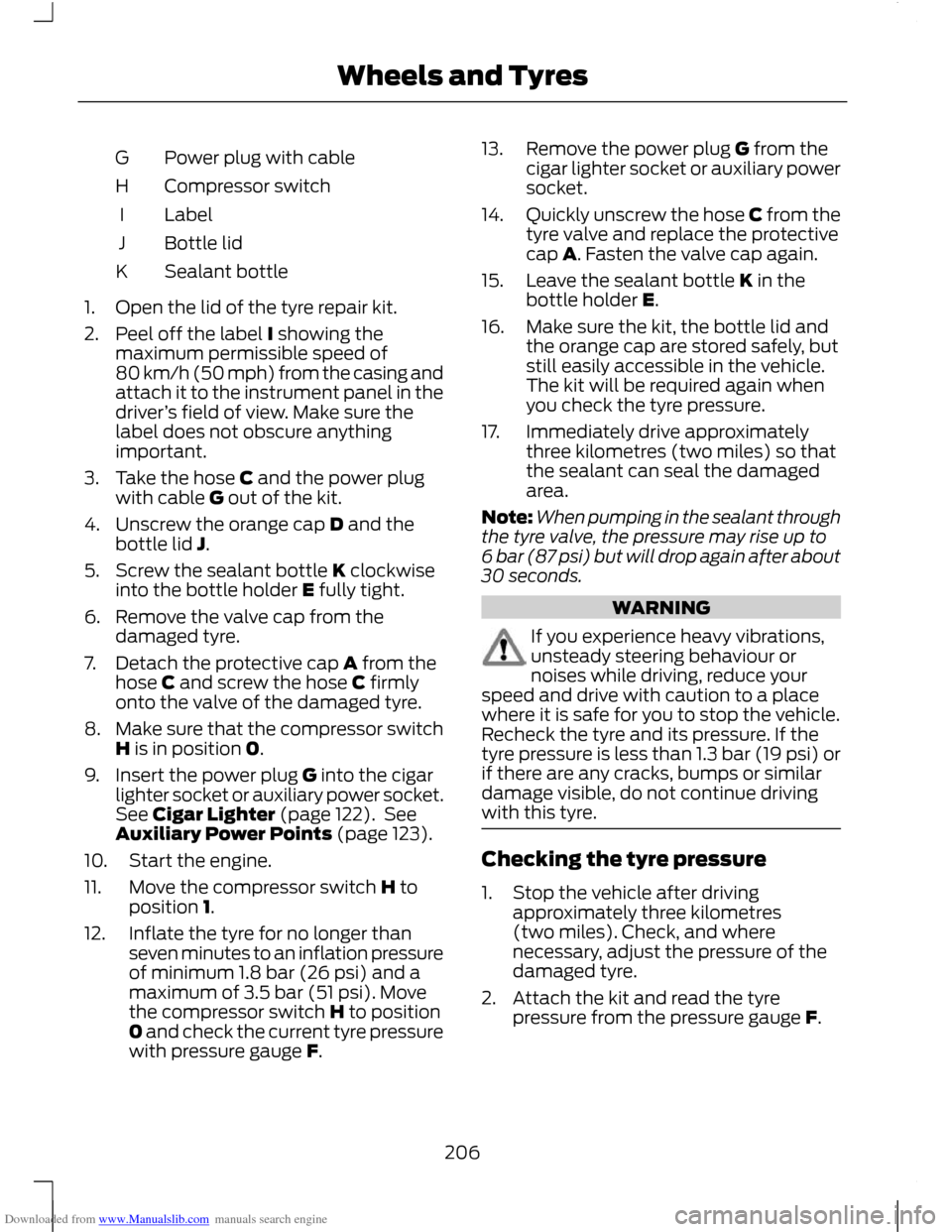
Downloaded from www.Manualslib.com manuals search engine Power plug with cable
G
Compressor switch
H
Label
I
Bottle lid
J
Sealant bottle
K
1. Open the lid of the tyre repair kit.
2. Peel off the label I showing the maximum permissible speed of
80 km/h (50 mph) from the casing and
attach it to the instrument panel in the
driver ’s field of view. Make sure the
label does not obscure anything
important.
3. Take the hose C and the power plug with cable G out of the kit.
4. Unscrew the orange cap D and the bottle lid J.
5. Screw the sealant bottle K clockwise into the bottle holder E fully tight.
6. Remove the valve cap from the damaged tyre.
7. Detach the protective cap A from the hose C and screw the hose C firmly
onto the valve of the damaged tyre.
8. Make sure that the compressor switch
H is in position 0.
9. Insert the power plug G into the cigar lighter socket or auxiliary power socket.
See Cigar Lighter (page 122). See
Auxiliary Power Points (page 123).
10. Start the engine.
11. Move the compressor switch H to position 1.
12. Inflate the tyre for no longer than seven minutes to an inflation pressure
of minimum 1.8 bar (26 psi) and a
maximum of 3.5 bar (51 psi). Move
the compressor switch H to position
0 and check the current tyre pressure
with pressure gauge F. 13. Remove the power plug G from the
cigar lighter socket or auxiliary power
socket.
14. Quickly unscrew the hose C from the
tyre valve and replace the protective
cap A. Fasten the valve cap again.
15. Leave the sealant bottle K in the bottle holder E.
16. Make sure the kit, the bottle lid and the orange cap are stored safely, but
still easily accessible in the vehicle.
The kit will be required again when
you check the tyre pressure.
17. Immediately drive approximately three kilometres (two miles) so that
the sealant can seal the damaged
area.
Note: When pumping in the sealant through
the tyre valve, the pressure may rise up to
6 bar (87 psi) but will drop again after about
30 seconds. WARNING
If you experience heavy vibrations,
unsteady steering behaviour or
noises while driving, reduce your
speed and drive with caution to a place
where it is safe for you to stop the vehicle.
Recheck the tyre and its pressure. If the
tyre pressure is less than 1.3 bar (19 psi) or
if there are any cracks, bumps or similar
damage visible, do not continue driving
with this tyre. Checking the tyre pressure
1. Stop the vehicle after driving
approximately three kilometres
(two miles). Check, and where
necessary, adjust the pressure of the
damaged tyre.
2. Attach the kit and read the tyre pressure from the pressure gauge F.
206
Wheels and Tyres
Page 222 of 296
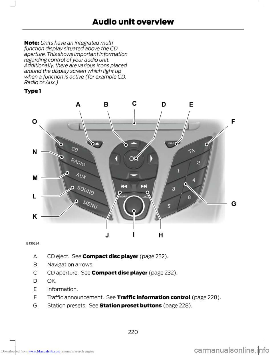
Downloaded from www.Manualslib.com manuals search engine Note:
Units have an integrated multi
function display situated above the CD
aperture. This shows important information
regarding control of your audio unit.
Additionally, there are various icons placed
around the display screen which light up
when a function is active (for example CD,
Radio or Aux.)
Type 1 CD eject. See Compact disc player (page 232).
A
Navigation arrows.
B
CD aperture. See Compact disc player (page 232).
C
OK.D
Information.
E
Traffic announcement. See Traffic information control (page 228).
F
Station presets. See Station preset buttons (page 228).
G
220
Audio unit overviewABEDFOGKLMNJHICE130324