FORD CAPRI 1974 Workshop Manual
[x] Cancel search | Manufacturer: FORD, Model Year: 1974, Model line: CAPRI, Model: FORD CAPRI 1974Pages: 205, PDF Size: 43.75 MB
Page 141 of 205
·0 ) Chapter 8 Rear axle
crowllwh(lcl teeth. Refer to Fig 8.' 7 where the corrcCl100l h paltcrn is shown, Also shown arc incorrec t loorh patterns ilnd the method of oi11
Chock the IrOllt wheels then lilck up the ,eaf of the Cill ilnd sUPPor! will> ilxlc S1
IUlld
10 lillli ted-slip diffc ronli"l-\.Ien er,,1
The IIllllwd·shp (I,fle,ent,,,1 's f,tled to 2 8 Spec,,,1 modl:ls ""d Its "';1111 purpose is to il,event wheef SPIll 01 the IIlsule ,ea, wheel when dnvin(l round bends or oul of l>emls w ith lull enOl/Ie powe, applied.
F i
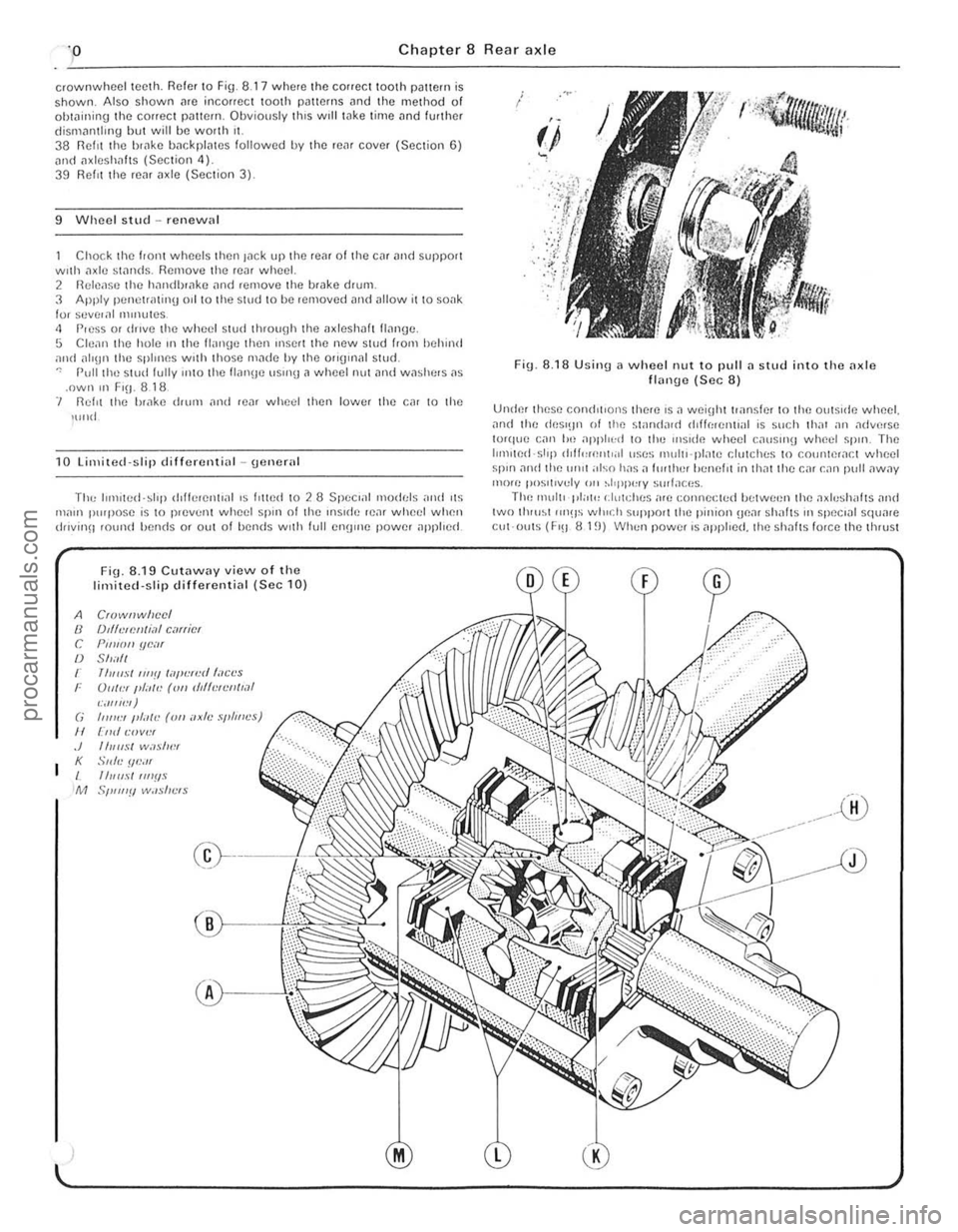
ll. 8.19 Cutaway view o f the limited·slip differential (Sec 10 )
A Crowf!whecl /J fJ'{""I!/IIi,,/ carrier r: PIllIOII ue .. " /J $h .. ,{1 r fhlll.I'IIIII!llill",,,,II/,1C<.'S r Uukr IJ{;,I<.-((III """Ht'nll,,1 ,;,/1 IIf,'1 ) (; 1"111:1 I"a/(: ((III axle .
)
i
F ig . 8.18 U sinll 11 wheel nut 10 pull il slud in to lhe ilJ(le
flonge (Sec 8)
Under these cond,tlons thNe I S il weiohttriln~IN 1 0 lilo oulslde wheel. ,111d lho deS'Bn of the standJIl1 (hlf(:relll,al is such Ihal all ,1dvmse I(uque con 110 ajlpl".:d 10 l11e Ills, de wheel ca"slIlII wheel ~pln, The l,lll ,W
Page 142 of 205
Chapter 8 Rear axle 141
lings apm! and compress the clutch plntes. The nction is varinble. depending on the power npplied. so tlMt under full power the dIfferential will lock completely nlld full torque will be appl;ed to both
11 Fa ult diagnosis -rear axlo
Symptom
NOIse
"Clonk· Oil nccelera tlon nnd deceh:ontlun
,... Ilenka\Je
)
renr wheels . Under coasting or overrun conditions the differential will operate as a normal stnndard unit. The unit incorpora tes four different;nl pinions
Worn axleshaft bearing Insufficient luhricant
Worn dlfferentinl houSIng bearings Worn crown wheel and pinion Incorrect crown wheel nnd pinion mush
Worn 1I. leshalt splrnes Excessive crownwheel nluJ pinIon bncklnsh
Pm ion oil senl Icnkrng ReM cove r gasket leaklllg 011 seal on
procarmanuals.com
Page 143 of 205
Chapter 9 Braking system
Fault rflnunosis -hrnking sys tem Foothrnk.c I)(!dnl -removal .1nd refluing From m ake caliper -overhau l .. Front blake cillipCf -removal ;1nd 'Cl,UUl\1 .... ______ ._ .................... . Front brake discs -inspection, ,enlov,,1 and rcl,!\in(J Front disc pilds -renewal , ....... _ ...... .. General description ..... .... ........ . ............ . H andb
Syste m type
I=rOl1t brakes ~c tt,ickncss :
Now ....................................... .
Min rmum.
Oisc fun ·out (ma~inlum including hub).
Mini'l1ulll disc pad lining Ihickness
Re ar brakes MInimum bfake shoe lining thickness.
Torque w re nch settings Caliper ....... ................. ................................... . Brake disc .................... . Backpl"te ........................... .................... .......... ................ .... .. .. .......... . Hydraulic unions. Bleed screw (ma~) .... Aecuf>Cfaling valve 'Clainel (Gi,ling)
Gonoral description
23
16
5 ,
G 3 1 18 20 19 14 15
Oisc brakes aro f;tted 10 Iho front wheels and drum brakes to the lea. wheels. Tho cable or cablo and rod opelilled handbrake oper:11es independently on the real wheels. A vacuum sorvo unit is fiued
" "tween the mastel cytinde. and loolbrake pedal to provide assistance 'en the pedal is depressed.
T he hy,aulic circui t is split frOnt and rear. Undel normal conditions
M,lSIC' cylinder -ove.hilul Milsle. cylinder -removill ilnd .e liuing . P.eSStue d,ffcrenliill swit c h -desoiplion .• e m ov,,1 and .el,ning P,essure ,educing valve · description. relllovill ilnd .er,llonu
Reil' i),lGkplilte · ,emov"r ilnu refining Hei!( i)r"ke shoes -renewal ....... .................. .............. . . Routine m"intenance ........ . ................. .
SlOp·lilmp switch - removal. re/rUlng and ildJustmcflI . Vilcuum servo unil _ description . Vncuum servo unil -rcrnovnl nod rcfiUing Wheel cylindcr -rcmovnl. ove.haul and ref'lIing
11 10 12 13 ,
7 2 17 21 22 8
Dlml hyd'i1ulic cif cuit. snlol Ironl i1nd rCilr WIth IlreSSU,e reducing v:llve in reil r ci.cui t on Iiller models. DISC I,onl brilkes i1nd self·ndjust illu rca .
(!rum brilkes. all wilh servo aSSIstance. Calrle or c.,blc .1nd rod operated handbrake on rear l)f"k es
12 .7 mm (0.5 in) 11.4 rnm (0.45 in) 009 nlln (0.0035 in) 3 .0 mm (0.118 in)
1.5 mm (0.059 in)
Nm 471068 41 1046 271031 71010 10 491062
Ibl It 351050 301034 20 to 23 5 to 7 7 36 to 46
both ci.cuilS operale in unison. howeve •. in the event of faIlure o f one circui t Ihe lemaining ci.cui l will p
Page 144 of 205
) Chapter 9 Braking syste m 143
2
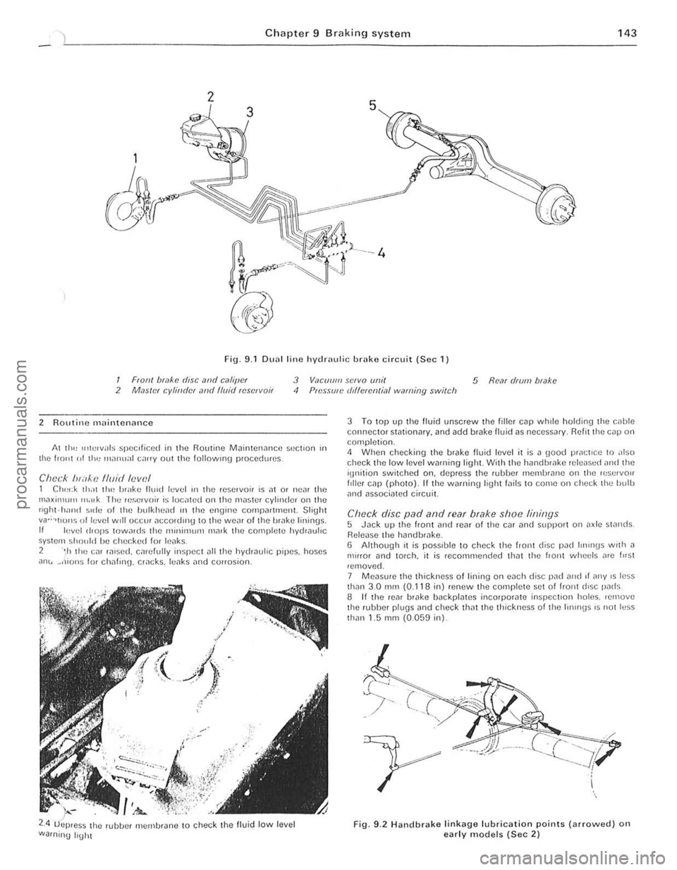
Fig. 9.1 DU
2 ROlltine maintenance
Al III<, u,h!lvals speClficed in the Routine M
2.4 ;-.-
uejJ.es~ the rubue' membrJne to check the fluid low level
Warning IrUht
3 To top up the fluid unscrew the fill er cap whrle holding the c,lhle connector sWtionar y. and add brake lIuid ns necessJr y. R efit the cnp on completion. 4 When checking the brnk e fluid level it is n good practice to also check the low level wnrning light With the hnndbwke rele
Re leuse the hilndb'
Fig. 9.2 Handbr a ke lin k ag e lubrication points (arro\Ncd) on early models (Sec 2)
I .
i
! j..
1:
, ,
procarmanuals.com
Page 145 of 205
144 Chapter 9 Braking systom
9 II there Dre no inspec tion holes, remove the wheels and drums In inspect the linings . 10 Where any lining is less Ih,111 the nllnimufll thickness, renew Ihp. complete SCI 01 re,ll b,~ke shoes. 11 Refi ' the drums lind wheels as necessary then lowe. tho em \0 thl) 9lOund.
Ch eck operation of servo lIoil 12 Visually inspCCllhe vaCUUll1 hose IClIding hom the inlet mlllllfolll Of air box 10 the servo unit fOf dc\c,iOf1l1lon and security. 13 Wit h the engine Slopped. dCI).es s the bra ke pedal several ,imes to dissipate t he VOC U\Ull hoUl the sorvo Imit. 14 Depress the b'i1kc 11Cdll1 wilh moderate pressure then Sin' I the
cnU illC . As the V
R/mew fhe /)rilke I/Ilid 21 lJIucd Ihe hyd.; ."loc sySle m as d"scllherl III Seelloll 15 ilUOwnl! II",
Ihe new h ,,,k\) Ih"d to COnlph: lely 1,lIlhe C:"CUtt he"I!1 bled . 22 AI Ihe sanl\) I"ne rcn,uve Ihe 'Ci" ",ake \I'lOn,s alld check tho wlu,,,1
cylonclers 10' leak"IJe.
3 Front disc pl1ds - renewal
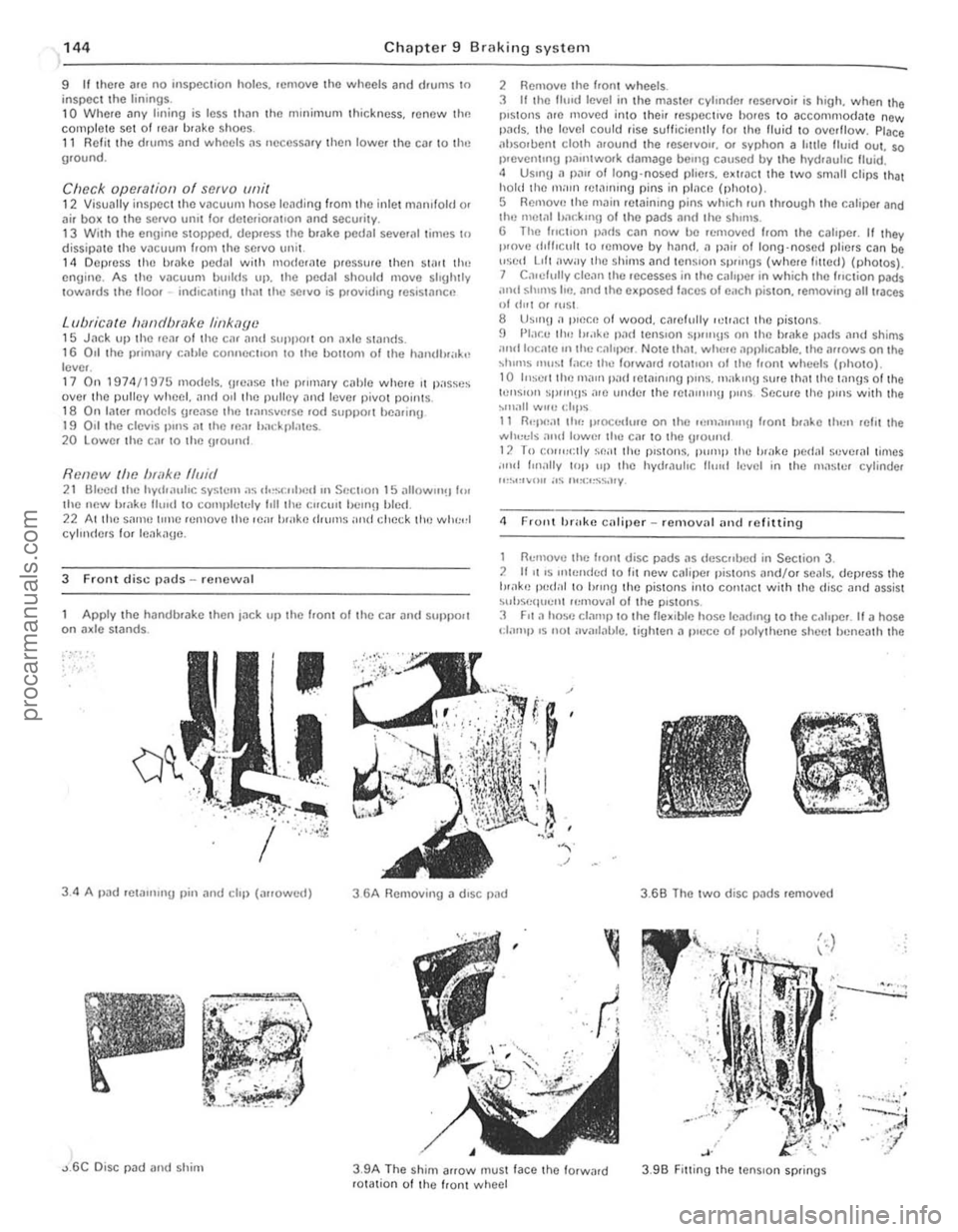
Apply t
he handbr
I .
. ~ .. " ,) •. :Y.
2 RemOV(l Ihe hont wheels.
3 It Ihe fhnd level in the maste' cylondel reservoir is high. when the pistons l1re moved into thei, respecI,ve bo,es to accommodate new pi1ds. thO leyel could rise sulticienlly fo, Iho fluid 10 oyerflow. Place ilhsoruent clOlh .1round the reSe,yO". o. syphon a Imlo Ituid oul. so 1)'Cven tUlg Pil"ltwOlk
<1 F rollt brake caliper _ rcmoy'll iltld refitting
1 nemove the f,on! disc pads i1S tie sc"lJc(/ in Section 3. 2 1111 'S Itll,,,,d,,(1 10 lit ncw Ci1tiper pistoll s "nd/o, seals. dep,ess the tH.1k'J Iwel,,1 10 hlUlU the pistons i"to COI11i1ct with thO (fisc and
'-.. ~
, .
3 .9B Fitting the tenS ion springs
.--.::.:.:; .
....... . ~,'
灲潣慲浡湵慬献捯m
Page 146 of 205
) Chapter 9 Braking system 145
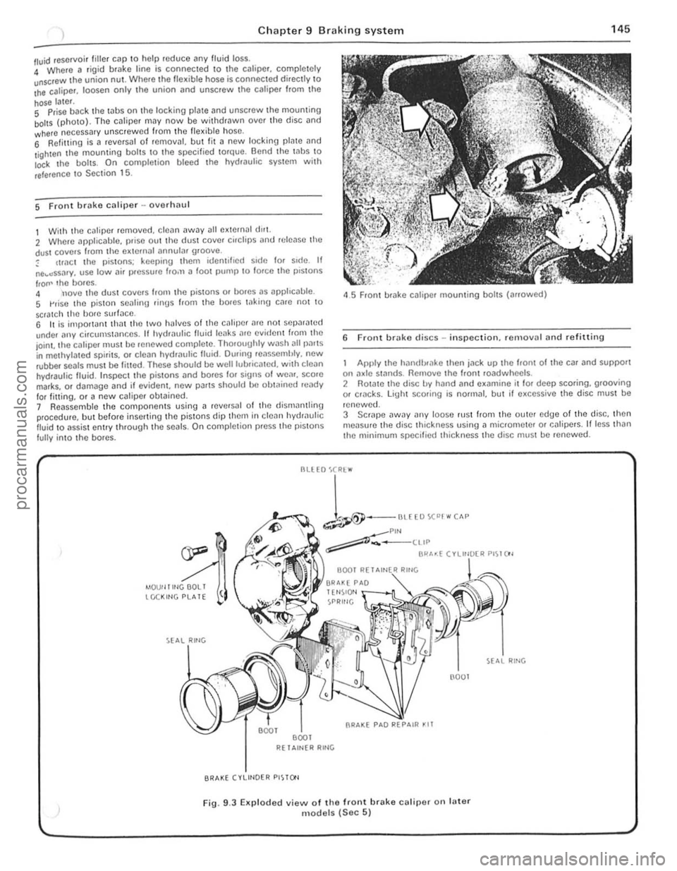
/ll.Iid reservoir tille , cap \0 help roduce any fluid loss. 4 Where a rigi d brake line is connec ted \0 the calipe r, comple tely unscrOw the union nUl . Where Iho flex ible hose is connected directly \0 Ihe caliper. loosen only .he union (lnd unscrew Ihc caliper f.om Ihe
hose later. S Prise back the laus on the locking plale and unscrew Ihe mouming boilS (photo). The cJliper may now be wit hdrawn ove r th o disc and where neCessary unscrew ed from Ihc flex ible hose, 6 Refilling is a revCfsal of fernOv;!I, but lit a new locking plate and
l ighten the mouming bol ts \0 the specified torque. Bend the Inbs \0 Io<:k I he boils. On comple tion bleed the hydwulic system wit h
reference \ 0 Sec tion 15.
5 Front brake caliper -ovorlulU l
1 With the c~liper removed . cle~n away all external dlr1. 2 Where applicable, prise out the dust cover cirClips
IrOIl' lho bores. 4 nove tho dust covers Irom the pistons or bores as apphc
45 Front brake caliper mounting bolts (arrowed)
6 Front brake discs -in spection. re rnovnl and refitting
Apply the hilndlxake then jn ck up the hom of the car and support on :1xle st:1flds. Remove the Iront roadwheels . 2 Rotate the disc by hand and examine il lor deep scoring, grooving or cf1lcks. light scoring is normal, but if excessive the disc must be
renewed.
3 SCrJpe
--
1-""£0""""" ~Plf'l ~-____ ttIP
BI"'~( ".",~"" PI~I()'
4IOUf llltlGOOLI tCCKltlG PLATE
R( 1 Altl{R RltlG
BRAKE (VLIHOER PISTO'l
(l001
Fig. 9.3 EKp loded view of the front brake calipe( on fater models (Sec 5)
RING
., .,
,
procarmanuals.com
Page 147 of 205
Chapter 9 Braking system
4 Note that in order to m,lintOIll even braking both discs should he renewed ill the sal1 1 e lime
5 T o remove il dl~c. first remove the tHlb as described in Chllpter 10 . 6 Prise lip th(J locklllU I"hs. unscrew the fOlll bolts. and remove the disc from Ihe huh.
7 Clcilll the Illllirnu !ilces of the disc and hub then locale the diSC on the huh and allgel the holt holes.
8 InScrt new holt~. tOI){)ther w rth new locking plates. and tiuhten them to the specrfre(1 torque_ loc k b y bending the tabs. 9 Th e huh Illily now he ref Illed with reference to Chapter 10.
7 ReM hrake shoes -rt)rlewal
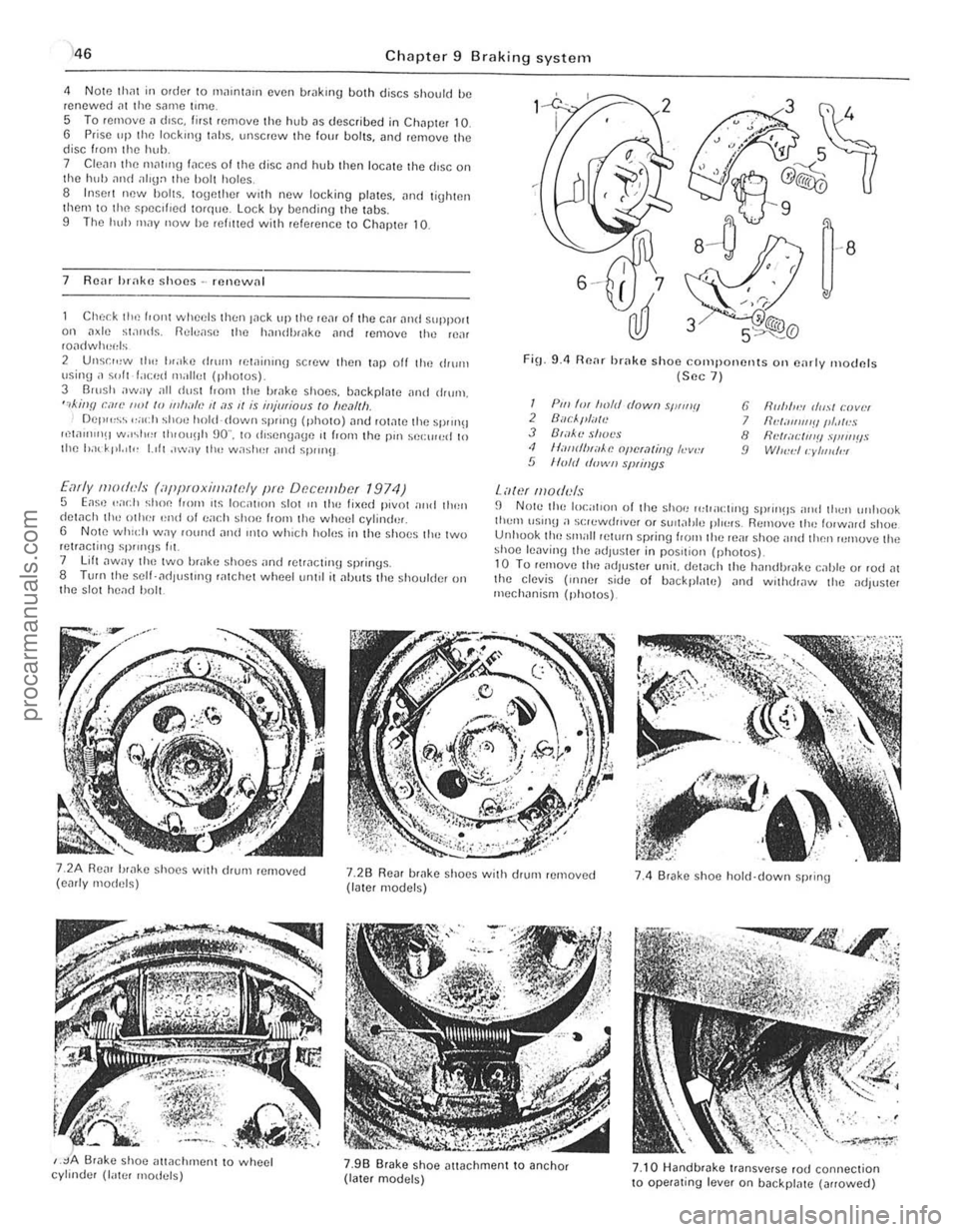
Check the front wheels th!:n lilck up the rem of the CM lind support on ,1~le stands. Rel(,a5e Ihe handbr,lke lind femove the reM roadwh~~els
2 Unsr",w th" I"ake drum lewinrnu scrow then t.1p off the ,IIurn \Jsing ;I ~"It f.lced milliet (photos) 3 Barsh away all dust I.orll the brilke shoos, backplate ilnd drum, ",killfl can' ""I /0 11111""., II ;I S 1/ is iHjmiaus to "e,11Ih Del""~~ ,,;och shoe hold-down sprrng (photo) ,lnt! rOt,lte the sprrn!! ",w"nIlH w.r~I"" th,ou!lh 90" , to rhsengage ,t from the pm sel:rr",d 10 Ihe had' pt. 'I" 1.,11 ,"wily 1Ill! w;'shel and spm}!J
Early moth'ls (iippmxilllawly pm Df!c()tllbcf 1974) 5 Eas,) .. ad} shoe loom ,t~ loc;rllol1 slor III the lixed pivot nrrd tllen detach th,-othe! '~nd 01 ea(.11 shoe f,om the wheel cylind'lr, 6 Note whld, W.1Y fOwul and IIltO which holus in the s hoes tlH~ two retracting sP""Hs Ill. 7 lift ,lway t ho two brake shoes "nd retracting springs. 8 TUf(lthe self- ad lust'ng ratchot wheetum,1 it alJuts the shoulder on t he s lot head bolt.
FiO_ 9.4 Renr brake shoo components Oil e,lrly moclnfs (Sec 7 )
I Pili 'm froft! dowII sWIIIII 2 Buc/."liTlt! J B',l~'l! shot's <1 II,-IIIrflHiiAe opcra/jllY h-v", 5 lIo/d d"wII slNil/ys
Lawf lII oduls
6 fir"",,:, (/",,1 r:lJvlH 7 IId;III1I1'!IIII.llr!S 8 flNr;Il:IIl'!! .,'I,"IIIIS 9 WI",,:II:yllJldl!l
fJ N Ole the local,on of the shoe 1"lpacl,no sprrll!ls nrld thell unllook tlwm \lSUl!l a s(;lewrh,vef or SUil;!tJle plo~"s. Remuv,) th" lorw,lrd shoe Unhuok tho small pelurn spring loom the reill shoe and then rumuve the shoe lenvinlJ the adJus!Cr in pos,tiol} (ph o tos)_ 10 Tu remove tim adjuster unit. del
,
j
procarmanuals.com
Page 148 of 205
Chapter 9 Braking system 147
Br;'lke IlIlInU
Wheel Adjustment
"m
cylinder --·-·_.L
-::'~~:.J/
I
'j
~
l
~
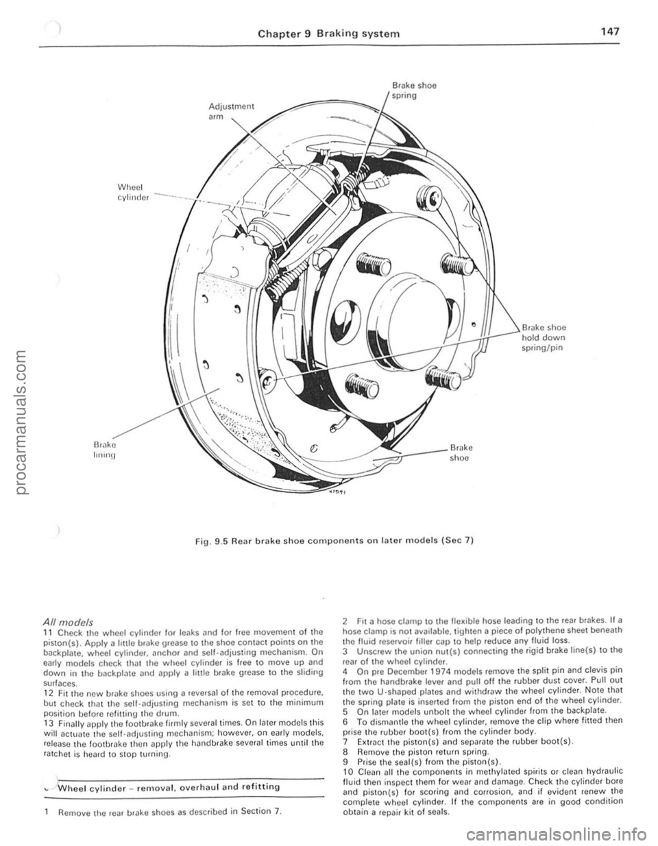
• shoe hold down spring/pin
Br.lke shoe
Fig. 9
.5 Rear brake shoe components on later m odels (Sec 7)
All models 11 Check the wheel cylinder lor leaks and lor Ioee moyemen t of the
piston(s). Apply a hule brake urease to Ihe shoe contac t points on the
backpla te. wheel cylinde r, anchOr and sell-adjusting mechanism. On
early models check th
but check that the self-.. djusting mechanism is set to the minimum
posi tion belore refilling the drum .
13 Finilily apply lhe loo tbrake firmly several times. On later models this will actua1e the self-adjus ting mechanism; however. on e
Wheel cylinder _ remo yal. oyerhaul and re fitting
Remove lhe rear urake shoes as described in Section 7.
2 Fit a hose clalllp to the fle~ible hose leading to the reaf br .. kes. If a hose ci
5 On I.ller models unbolt the wheel cylinde r from the backplate .
6 To dismantle thO wheel cylinder, remoye the clip where fitted then
prise the rubber boo t(s) from the cylinder body.
7 Extr.lct the piston( s)
9 Prise the seal(s) from the piston(s) , 10 Clean all thO compo nents in methylated spirits or clean hydraulic fluid then inspec t them for wea r and damage. Check the cylinder bote and piston{s) 10f scoring and corrosion. and il eviden t renew the
complete w heol cylinder. If the components are in good condition
ob tain a repair kit 01 seals.
i.
i I
II
j
I ;
procarmanuals.com
Page 149 of 205
)8 Chapter 9 Braking system
8
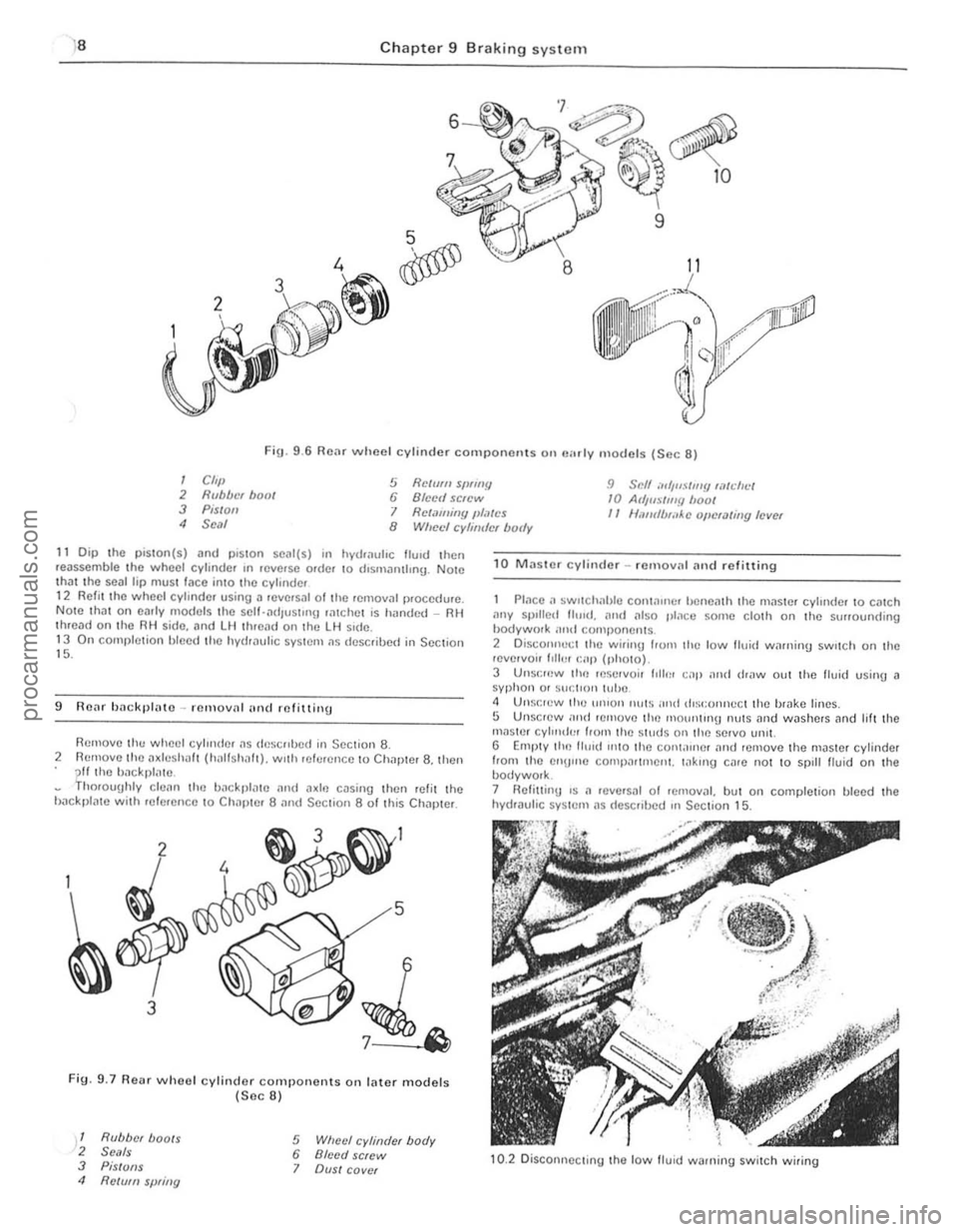
Fig. 9 .6 Rear wheel cylinder component s on "",I y models (Sec 8)
I Cft,} 2 Rubber hoot 3 Pis/oil
5 Relmll SfJflflY 6 Blcell screw 9 Scff ",',uSilll!! wtdll.:/ 10 At/jlls/my boof
4 Seal I Retaming JlI,~tcs II Ullfufb,;,Ac oj/cUlling level 8 Wheel cyhirdcr body
11 Dip the piSlOn(s) and plSlOn SC
9 ROilr backl}lato -rClllovn! (IIHI mfittillg
Remove th ... wheel cylllllier ~s
Fig. 9.7 Re .. r whoel cylinder components on lilter models (Sec 8)
1 Rubber boots 2 Se'lls 3 PiS/OilS 4 Re/vm spring
5 Wheel cylinder body 6 Bleed screw 7 OVSI cover
1 0 MJsle r cylinder -rcmov;11 Jnd refitting
P lace a ~wllcIH'hJe COI11~lIler benem h Ihe mJ$le f cylinde r 10 cmch ,1ny spIlled Ihud ... Mil also place ~on,e cloth on Ihe surrounding hodywork ;lml componems 2 Disco"nect Ihe wirinlJ lrom the low tluid winni,,!) sw,tch on the ,evelvoir 1,lh.1I r:ap (photo).
3 UIlSI:f(lW lill) reservoir 1011111 cap and dr"w out the flui(1 using J syphon or sucl'o" l(,be <1 Unsocw ("u un'on Illl(S IOnd rlist:onncct Ihe b,ake lines. 5 Unscrew lOud r emove (ill) nlolUwng nulS and washers Jnd lilt the mnster cyl",du' hom Ihe Siuds Oil Ih e servo lmll. G Empty llin tlu,d 11010 llie con l,urlcr Jnd remove the master cylinder
from Ihe enU",e comp(lrtmeni. Io1k,ng cllre nOI 10 spill Iluid on the bodywolk. 7 HeliuinU 's II ,eve'slIl of removJI. but on completion bleed the hydraulic syslem IIS (Iescribed In Section 15.
10.2 Disconne cting the low lIuid warning switch wiring
procarmanuals.com
Page 150 of 205
1 Chapter 9 Braki ng system 1 49
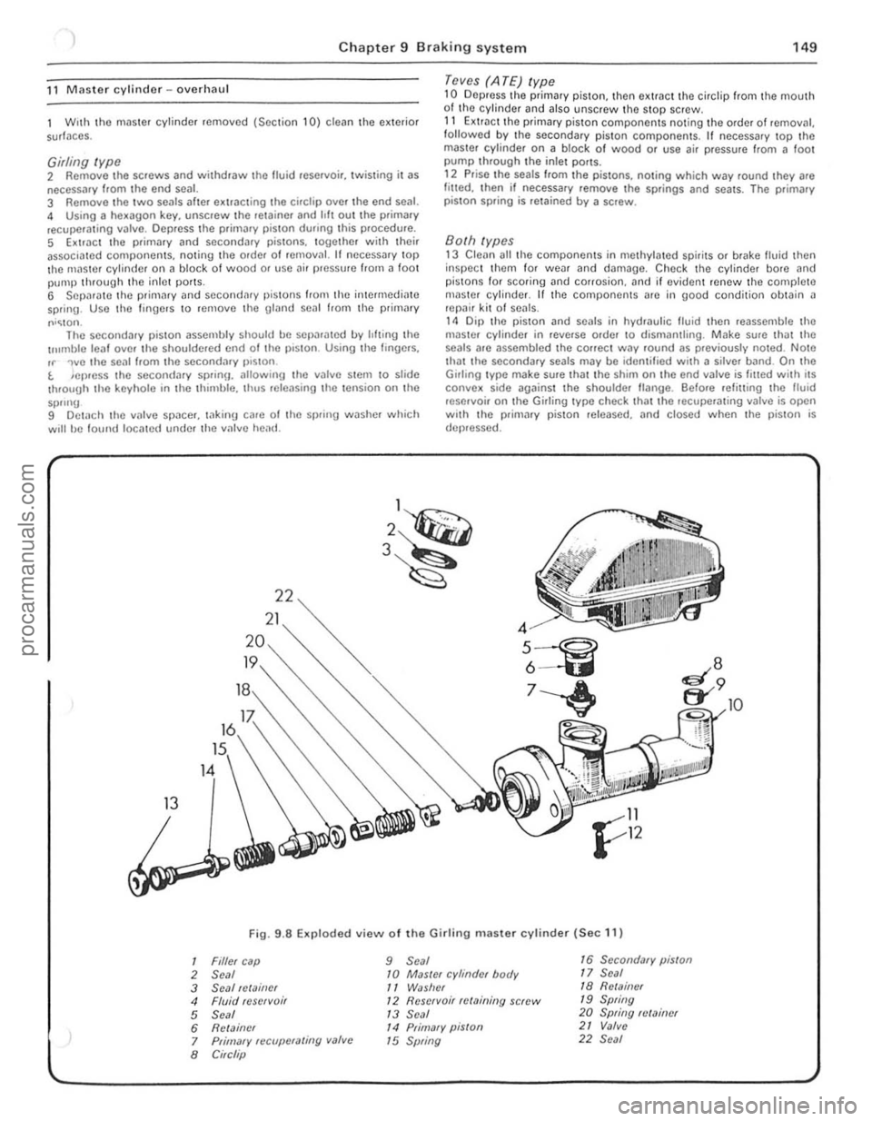
,1 M aste r cylinder -overhaul
With tho m
recuperating valvo. Oepress Ihe primll'y piston during Ihis procedure. 5 Exl.;'!ct Ihe primary and secondary pistons. IOgether wi,h their associated components. noting Ihe order of lemOlln l. H nccessary top Ihe master cylinder on a block of wood or use air pressure from il foot pUIllP through the inlel porlS. G Separate rhe primmy ,10d secondary l)is10 11S irani lha intermediilte
sprinu . Uso tho !inUe.s 10 remove tile Ulilnd seDI from the primil'Y
r""' lon .
The secondil'y piSlon assembly should ho sOfh"ated by lilting the u"mblo leaf ove , Ihe shouldered cnd 01 tho viston . Using the lingo,s.
rr 'wo the se
9 Dotach lhe villve space ,. tilking c
master cylinder on a block of wood or use air pressure from a 1001 pump through tho inlet ports. 12 Prise the seals from the pistons, nOling which way round they are lilled. then il necessary remove tho springs and seals. The prima ry
pis ton spring is retained by a screw.
Both types 13 Clean all tho components in melhylated spirits or brake fluid then
inspec t them for wear and damage. Check the cylinder bore and pistons for scorinu and corrosion. and if eviden t renew the complete nI
1
2~
3~
13
1
2
3
4 5 6
7 8
R
22
21
Fig. 9
.8 Exploded view 01 the Girlin g master cylinder (Sec 11)
Filler cap 9 Seal 16 Secondary piston
Seal 10 MaSler cylinder body 17 Seal
Seal !Clainer
11 WiJslrer 18 Rell11i1er
Fluid reservoi r 12 Reservoir relaining screw 19 Spring
Seal
1 3 Seal 20 Spring fl/Miner
Relainer
14 Primary piSlon 21 Valve
Primary fCCllpCfaling valve
15 Spring 22 Seal
Circlip
10
!
" 1 ,
1
I
!
!
I ,
J
,[
1
I
I
; .
!I ' i ;.
procarmanuals.com