key FORD CAPRI 1974 User Guide
[x] Cancel search | Manufacturer: FORD, Model Year: 1974, Model line: CAPRI, Model: FORD CAPRI 1974Pages: 205, PDF Size: 43.75 MB
Page 113 of 205
Chapter 6 Manual gearbox and automatic transmission
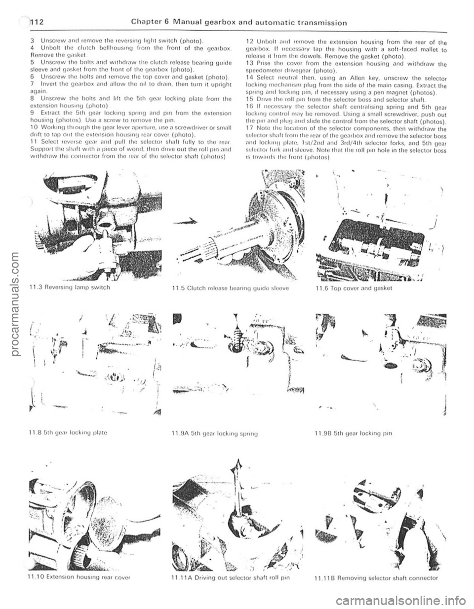
3 Unscr(lw .1ml remove Ihe reversrnu IrUtli SWilch (rhOIO). 4 UnbO lt the clulch bellhousrrl\J f,om the /,onl of the ge~rbox. Removo Iho gaske t 5 Unscrew tllo bolts .111<1 w,thdr
7 Inve,1 the UflilrllO x
I I Select revct~e !Ica,
12 Unholl and removc Iho extension housing Irom the ,ea, of Ihe
!)en,box . t1 nece5snrv lilP tho housing wrth a soft·/aced mallet to releilse ,I t,om 1he dowels. Removo tho gnske ! {photo}.
13 P"se Ihe cove, from th e ex 1ension housing Dnd withcfrnw the speedome1e, d"vc\Jenr (photo). 14 Selec i neut,
)
r
I
~~ . '
~~~,.,::
11.3 Revc,sm!t lilmp switch 1 1.5 Clutch rdense 1.K.'111"'!1 gu,dc sl(:cve 11.6 Tal) cover and tPske
I
( j • , .
'r" i'
I ,,J'" , i
I I
Ji;:;:~"'-'--·ft ; . -. '" . I
•
.-~:~'':''-'',:.-.,
I .-. " J
11 85th \)e;II lockrrlU plilte 1 1.9A 5th eil' lock"' SP""!t 11.9B 51h !)C
11 1 1 B Ilemovong scle<:tor shaft connector
c
procarmanuals.com
Page 117 of 205
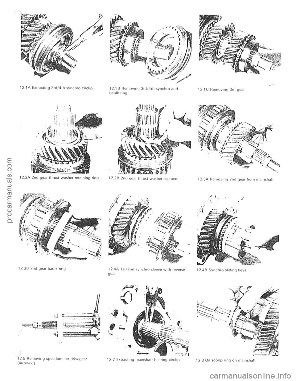
121A EXtlnClinn 3rd/4lh synchro cuclip
, .
" '11
1" I . ~ .
~.
:j
12.2A 2nd ge~1 thrust wllshCI rewining ring
12311 2nd gOD! h~ulk rmg
)
125 R"r"ov"'g speedometer d,ivegclI' (nrrowed)
12.111 Rel11ov"'11 3,d/4Ih synchro ilnd bnulk "n\l
, ~j.
,~
12.28 2nd \)(1,,, Ih'rrsl w,,~her ~"IJrrH,rrl
12.4A 1 sl /2nd synduo ~Ie"v(! wrth reverso ge~r
1 2.7 EXlractrng m~rnshilh hca"ng ci,clrp
12.1C RemOVln~13,d Bt,nl
12.3A RcmovlIlU 2nd uonr frOIll lI1~insh1lfl
, .
12411 Syncluo shdlll\) keys
128011 scoop rll19 on 1l1~,,'shJft
灲潣慲浡湵慬献捯m
Page 119 of 205
18 Chapter 6 Manual gearbox
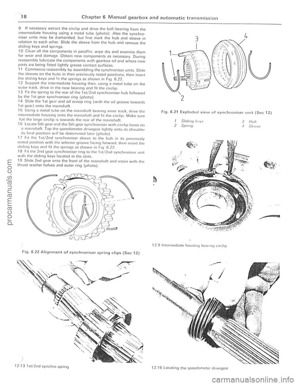
reassembly lubriC31C the components WIth geJrbox oir and where new p.).I$ alc ooing lilled ligh tly grease contact sullaces. 11 Commence reassembly by assemb ling the synchroni se. units. Sh(IC the sleeves on lhe h ubs in the ir previously noted positions, t hen insert
the slodmg keys .-mel f" Ihe springs as Shown on Frg 6 .22 .
12 SUllPOrl th e inte.rneelrate housing then. USrrlg a mewltube on the oute, I rack. drive in the new l.loarrngllnd lit I he cirelrp 13 F it Ihe sprrng 1 0 th e rea, 01 tho 1 sI,2nd s yn chroniser hull followed by the 1 Sl gear synchronise, 'ing (phOIO) 1 4 Sl ide Ihe 1 S l go., r and oil SCOOp rin g (wilh the oil uroove 10 w ,lIds 151 \lear) \"lniO tho mllmshafl. 15 Us,ng a metal lube on th o maonsh.11t he"rnl{) 'nner Ir ,lck. drive th e 'rlle,med,.-Ite housing Onto the ma'llshllh nnd 1'1 Ihe circl'll. Make sure hm Ihe larg e c"clip.s IOwards the rc." ollhe m,'"ls haf .. 1 G l ocate 51h gear ilrld the 51h goa, synchronrse . wilh Crrchjlloose on p m,llllshilft . Taplhe speedometel drrvenco1l Iogh.,y omo ,ts shoulder "~S lon"l j.lOsOIOon w,1I be de lerm,ned filter (,11\0\0) 17 F, . the 1 stJ2nd synchronisc r s'eeve 1 0 Ihe huh on 1\5 prell'ously n Olod posit,on wit h the selce ,ol groove 'ilCmU 10 rw,lrd. Ih,,,, mscrl the sl'd'nU keys ,1n(l lilt"O sp,ings as shown "' r-,U 672. 18 FIl the 2nd ueil' sync hronisc! ling to the 1 sl/2ml synch't"lIS'" "'HI wolh the shtllnu keys located in the slol~. HJ Slid e 2nd ge<"ll onl0 Ihe front 01 th e (ll ",n Sh;lh <"Iml rC1
""'=~~ ';e:o/l -~ &;J -~;V
Fig. 6 .22 Alignment of syn chroniser spring clips (Sec 12)
12 .1 3 lSI/2nd synchro sp ring
FiU · 6.2 1 E~plodcd lIi(!w oJ sylldllOlli s(!r ,,,,,I (Soc 12)
/ Sh(llIJiJ A,·y.~ 2 SPIIJIY
,
I!l1. '. ~~':;.'
1 2 9 Illt!lHnelhme hOllsm!j he ... ",,!) Cllt:i,p
1 2.1
6locatiny the speedometer Ifrillegellr
3 N,,1> ./ S","cv~'
dfO:. , . ""lJ' . ., ..
~~-.••
procarmanuals.com
Page 120 of 205
) Chapter 6 Manual gearbox and automatic transmission 119
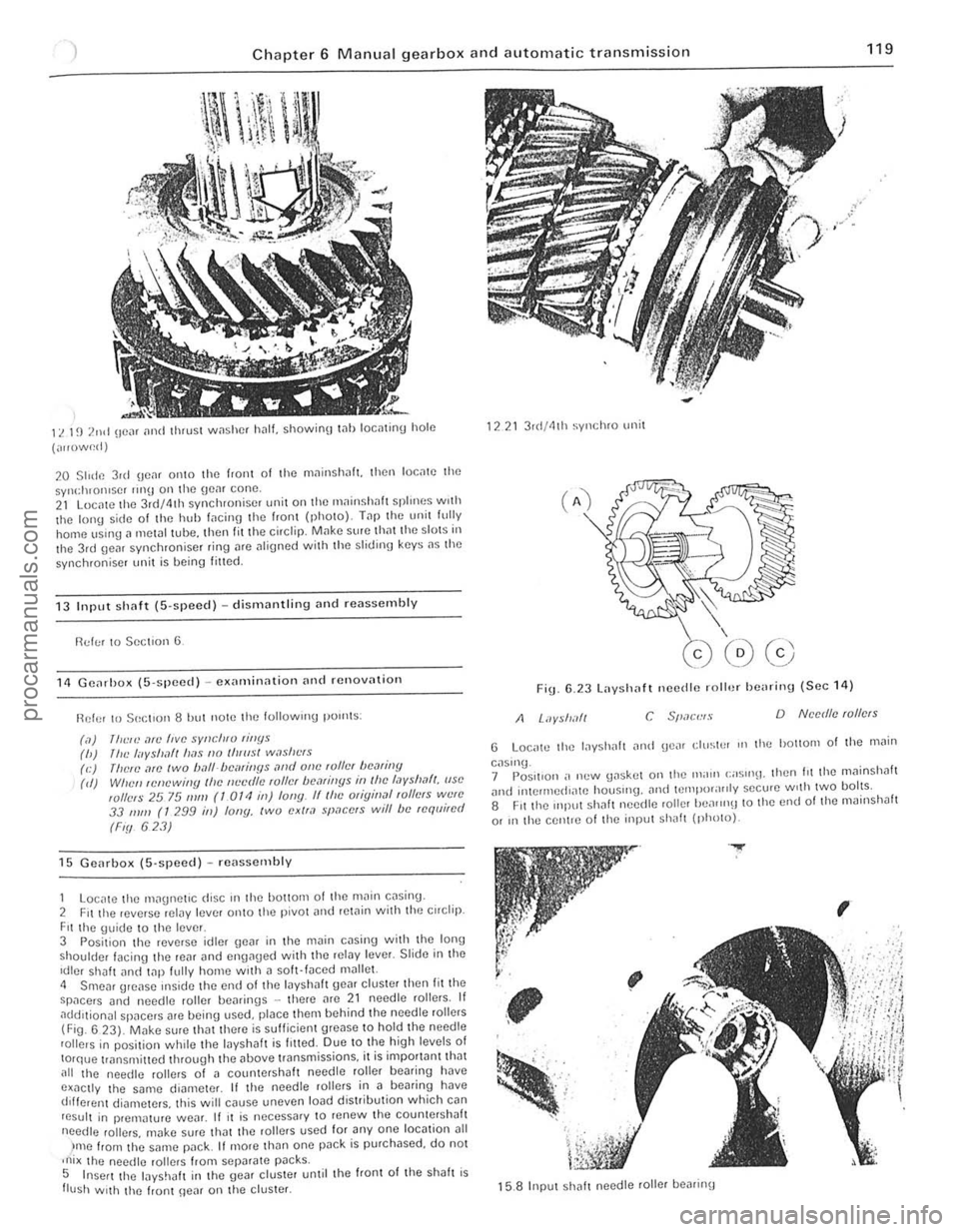
11. 1~) 2nd (Ie", [Inti thrust w,1shcf h.1l1. showioO t .. llloctltinu hole
(",,()w~d)
20 Slide 3ul \jC,lf 01110 the f,aiH 01 the mninsh
13 Input sh(lf( (S·speed) -dismantling Dnd reassembly
!'ld!;! to Section 6
11 GCil,ho)l ([i·spced) -C)lamin,lIion [In(1 rcnov[ltioll
Ref or 10501:[ '0 118 hut now the lollowlng pOllltS :
(,1)
111<:,,) ,1fI! five sYllcll,v rillYs (h) /IlL' I"yshlft lI[1s 110 IIIlIIsl w,lsllt"s (e) (lielL',1ro IWO ball-/)cmiIJYs ,lrId olle ,01lcI hCMiny (d) Wile" ,cnewi"y Ihc IIL'cr/lL' ,01lcI /)(1,1/ill[lS ill I!lc I,Jyslml/, (ISO wllels 25 75 111111 (1 OTt! ill) fony. IIlhc Oligin,ll ,ollers W{!lC 33 111/11 (T 299 ill) lony, two exll,l space's will be requi,ed
(Fiy 623)
15 Gcarbox (5'SI}Cc(l) -rC
Fit the \juidc to the leve r 3 Posit ion the reverse idler \Je~r in the m~in cDsill\j with the Ion,) shoulder facing the reill and en{lllued with thc ,eiDy Icver. Slide ill thc Idler shalt lInci t
)me from t he SMne l"JilCk It more than one pDck is purchased, do not ,ni x lho needlc rol lers from sepilrate p~cks. 5 Insert the layshJlI in the gear cluster unlil the front of Ihe shah is flush With the frunt \Ie~r on lhe cluster.
1221 3 r(I/41h syl1chro unit
Fig 6.23 Layshaft necdle roll.)/ he
G Loc,.tc the lilyshah iln!! gCilr ell/stP' III tho hOllom of the .11il;n
caslnu_ 7 Pos.1I0n ,. n(.'w \Jaskot on the Ill;nll (;;05"'11. Ihen hi the mllinshah ilnt! inlCrll1ed"l\C houslIlg. and IClllpor;I"ly secu.e w,th twO bolts. 8 Fit the mll"t Shilh needte roller heilrrn\J to the end 01 lhe mainshJlt
or In the centle 01 lho input Shilh (photo).
.....
,
~
; , .. '-; . '. ~, .
,
15.8 Input sh
i 1 ,1
I
procarmanuals.com
Page 121 of 205
)20 Chapter 6 M anual gearbox and automatic transmissio n
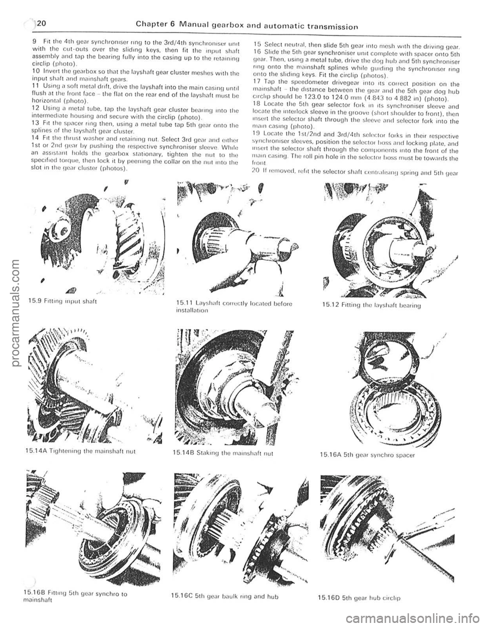
9 F it the 4th gCill syncluolliser "n9 to the 3rd/4lh sym;luOI"s(1f 'HUI with lhe c:ul-outs over the slidlllg k(lYs. then fit the UlPUl shalt asscnlhly i]n(l lilP the bearing fully into tho casing up 10 the rclo1llunu circtip (photo).
10 Invert Ihe \jCo1rilox so Ihil! the l
12 Us;n!).1 mel,lilllbe. lilfl the Inyshaf gear cluster be,IIPI'!J 11110 the inlcrmcd'
15 Seleci neulrnl. then slide 5th ge", IlItO mesh WIth the driVing Be",. 16 Slide the 51h gem synchroniser unll complete with sp"ce[ Onto 51h Oll"r. Then. usrng.l metal tube, drive Ihe dO\1 huh "lid 51h synchronlser flng OnlO Ihe 1ll",nsh,,11 splines whIle UlOld"l!) the synchronIse! 111111 onto Ihe shdlll[J keys. Fit the circhp (pholUs).
17
T"p Ihe sp eedometer drivegeilr "HO ItS COrreCI poslilon on Ihe mollllsh"ft -the dlsWllce belwoon Ihe HeM 'Illd the 5th gO,l[ dOll hub c"cllp should be 123.0 to 1 24 .0 111m (4 843 10 <1 882 Ill) (nhoto). lB Loc"le Ihc 5th He", selector fOlk In liS syn ch ronlSN sleeve "nd loc"le Ihe Interlock sleeve in Ihe uroov", hhol! Shollider 10 front). then InSurt the seleClor sh~1t through the sleeve ,1nd SeleCIOr fOlk InlO the "'aOll r.,lsll1\J (photo).
19 LocnlC the lSI/2nd "nd 3rd/4th Sf)I'~rIOr IOlks 1(1 Ihell respecllve ~Yllcillonlser sleeves. posilion the selectOl !ross
20 If If!rnoverl. 'ef'l Ihe seleCIOr sh,,11 (:"nlr,, 11~1I1!1 sprinU ",ui 51h \Ie",
.' /
15.9 FI1l1I1\1 Inpul shnl1 15.11 L;,ysh;r!t corruc tly located hefore inst,111,11101l 15.12 F,ltintllile Inysllilft hearing
15. 14A Tlghtelllng thc rn"insha fl nut
15.16B F'lllI'\) 5th genr synchlO to m~inshalt
15.148 Slak,n\1 the rH.lloslrall nul
15.16C 5th \le,,, haulk flng Jod hull
15.16A 5th gem synchro spacer
15. 160 51h gear hub {:ilchp
procarmanuals.com
Page 134 of 205
1 Chapter 8 Rear axle 133
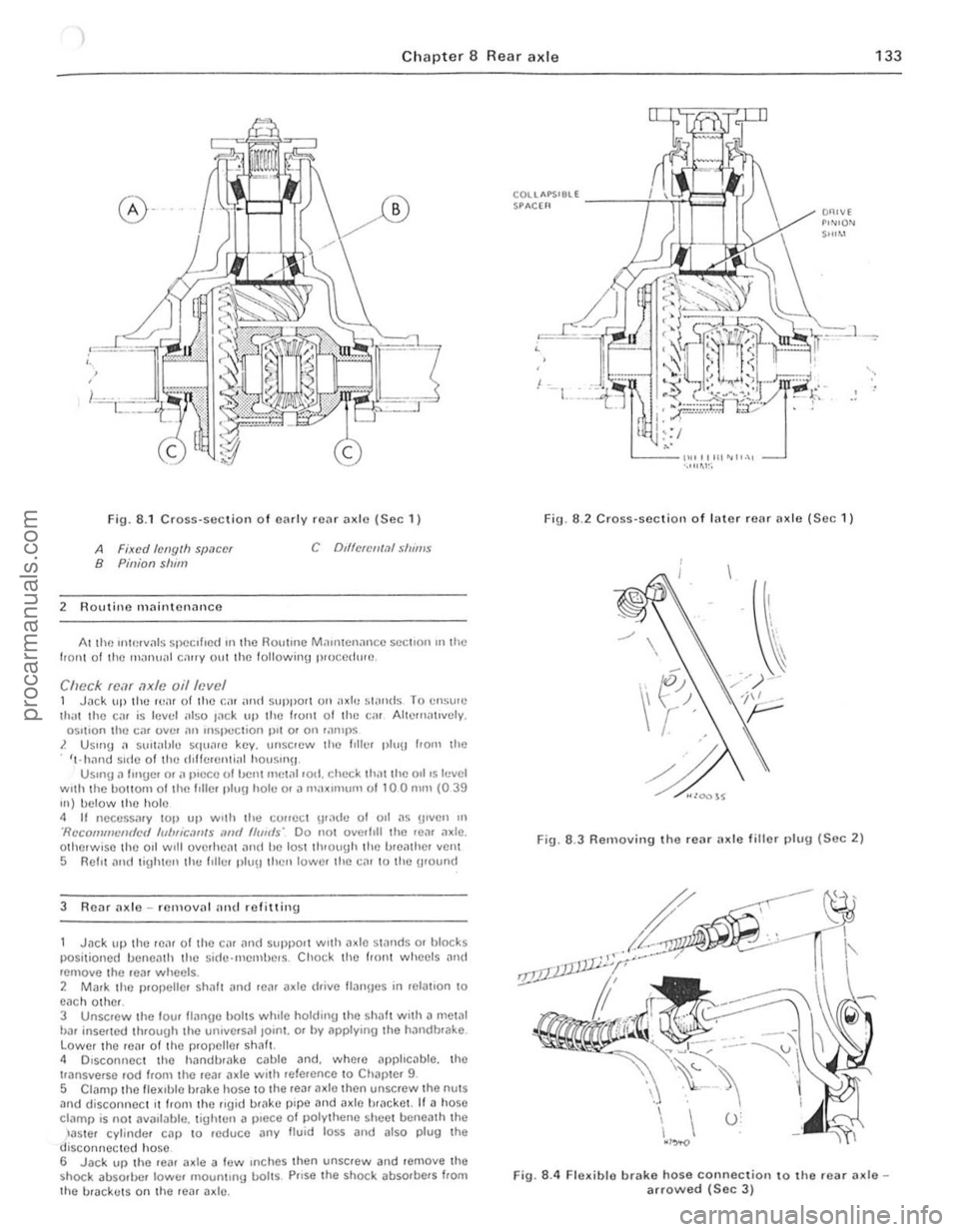
Fig. 8 .1 CrOSS-Sl!ction o f cnrlv rCilr ;1xlo (Sec 1)
A Fixed /ellglh SIJ.1C(!f B Pinion slum
2 Routino mnintcnoncc
C Dd1clCII1.11 S/II"'$
At lhe uHerv"ls specIfIed 111 the HOlltmc M.111l1cn;mc c SCCllon III the 110111 0 1 the mnnu;1I c""y oul the following p,uccdw(!.
Check fcar axle oil level 1 Jilek lIlllhc IvaI of the Cil! ;uHf suPPOtl on axle ~I"nds T o C!lSI'''') li1,'l Ihe Cilr is lellel ;,150 I
3 R e
posi tioned lIancnlh the sid(Hllemhe.s . Cho ck thc tronl wheels and rcmove the .ear wheelS . 2 Mark thc p.ol>elle. sh;J1! ilnd .eil'
t'ansverse ,od from the .ea. (Ide wl,h refalCnce 10 Chal >!el 9
5 CI
COUAPS'8ll -----i--i!~e"'.!i SPACH'
,
Fig. 6 .2 Cross·sc ction of I"ter rear Ilxle (See 1)
Fig. 6.3 Removing the rear ax le fillo r 1)lug (Sec 2)
Fig. 8.4 Flexible brake hose connection to the .ear axlearrowed (Sec 3 )
procarmanuals.com
Page 150 of 205
1 Chapter 9 Braki ng system 1 49
,1 M aste r cylinder -overhaul
With tho m
recuperating valvo. Oepress Ihe primll'y piston during Ihis procedure. 5 Exl.;'!ct Ihe primary and secondary pistons. IOgether wi,h their associated components. noting Ihe order of lemOlln l. H nccessary top Ihe master cylinder on a block of wood or use air pressure from il foot pUIllP through the inlel porlS. G Separate rhe primmy ,10d secondary l)is10 11S irani lha intermediilte
sprinu . Uso tho !inUe.s 10 remove tile Ulilnd seDI from the primil'Y
r""' lon .
The secondil'y piSlon assembly should ho sOfh"ated by lilting the u"mblo leaf ove , Ihe shouldered cnd 01 tho viston . Using the lingo,s.
rr 'wo the se
9 Dotach lhe villve space ,. tilking c
master cylinder on a block of wood or use air pressure from a 1001 pump through tho inlet ports. 12 Prise the seals from the pistons, nOling which way round they are lilled. then il necessary remove tho springs and seals. The prima ry
pis ton spring is retained by a screw.
Both types 13 Clean all tho components in melhylated spirits or brake fluid then
inspec t them for wear and damage. Check the cylinder bore and pistons for scorinu and corrosion. and if eviden t renew the complete nI
1
2~
3~
13
1
2
3
4 5 6
7 8
R
22
21
Fig. 9
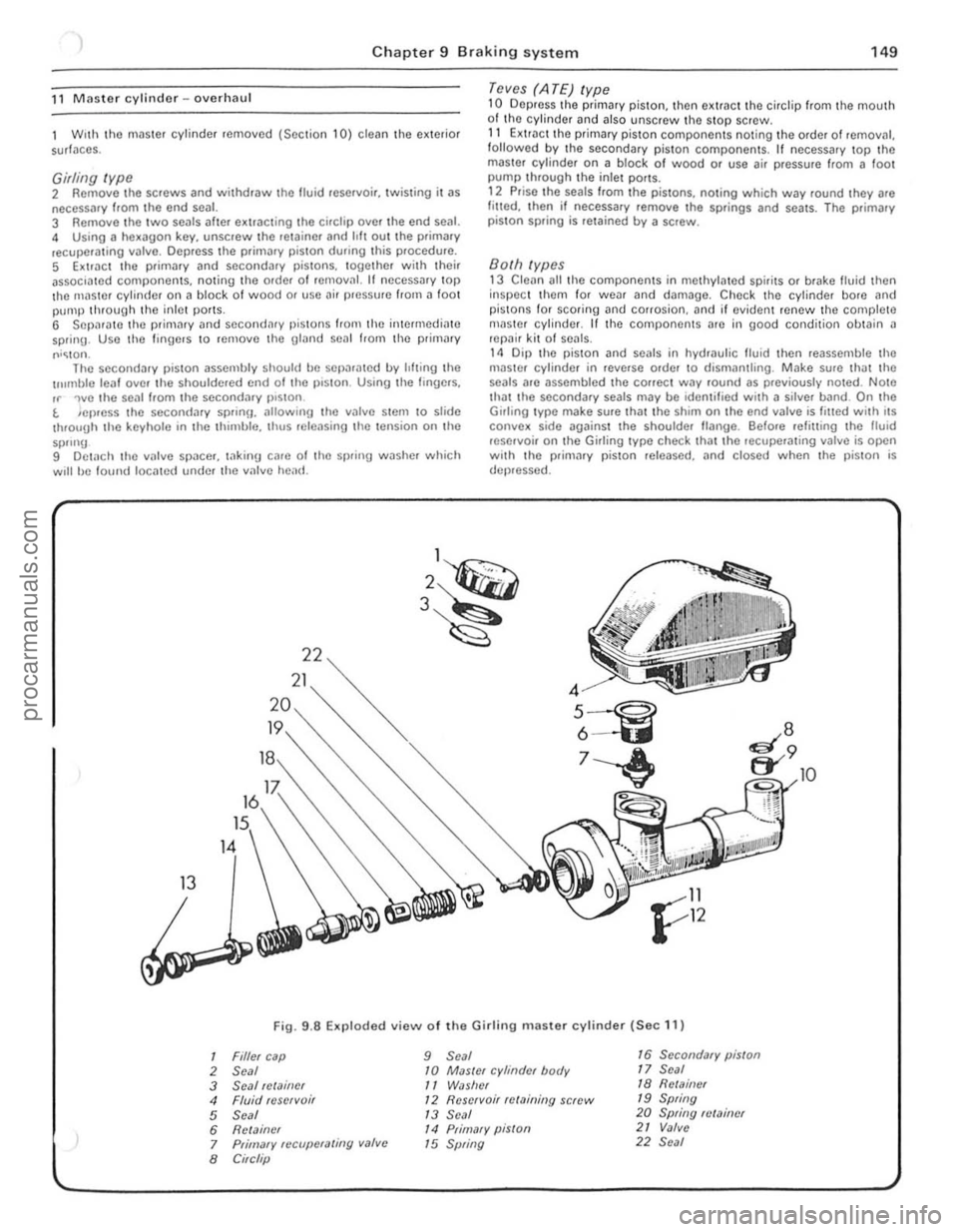
.8 Exploded view 01 the Girlin g master cylinder (Sec 11)
Filler cap 9 Seal 16 Secondary piston
Seal 10 MaSler cylinder body 17 Seal
Seal !Clainer
11 WiJslrer 18 Rell11i1er
Fluid reservoi r 12 Reservoir relaining screw 19 Spring
Seal
1 3 Seal 20 Spring fl/Miner
Relainer
14 Primary piSlon 21 Valve
Primary fCCllpCfaling valve
15 Spring 22 Seal
Circlip
10
!
" 1 ,
1
I
!
!
I ,
J
,[
1
I
I
; .
!I ' i ;.
procarmanuals.com
Page 155 of 205
)4 Chapter 9 Braking system
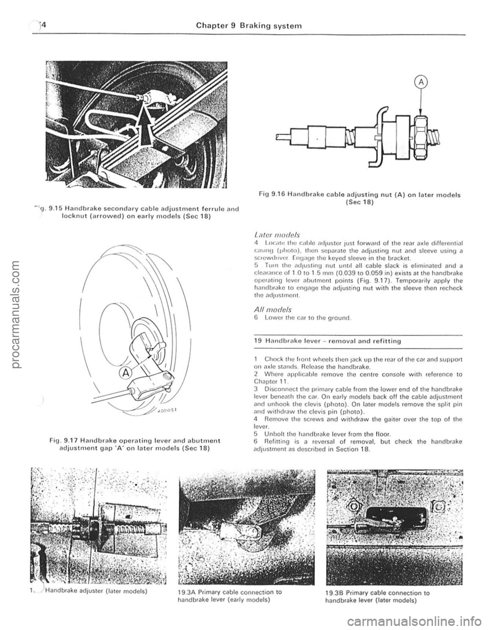
Fig 9 .16 H an dbrak8 cable adjusting nul (A) on later models (Sec 18) ~'9. 9 .15 Handbrako secondary cable adjustment fonu le and lockn u t (arrowed ) on early models (Soc 18)
I
Fig. 9 .17 Hnndhrnke operating lover n n d (llwtment (ldjuSlment gn p ·A' on later models (Sec 18)
'-iller mode!!s 4 LO(:,'I" trw r.al,lo .1dlUS1Cf lust forWi1f(1 01 the 10." axle dillCrcntinl , ;;.~.IIl!J (,.holn). then Sflp,l'ate Ihe ndjus\ing nul and sio eve usinIJ II se.ewtl""cr ["n,'IIO lhe keyed sleove in the bracket.
5 T 11m Ihe lldlu sling nul unlot all c.,l>lo slilc k is eliminated and a cleiuallr.e of I 0 '0 1 5 mill (0.039 to 0.059 in) exists at tho handb'Jke ope.aling 10l'm .. butment points (Fig. 9.17) Temporarily apply the holn(i!),,,kc 10 cnUage t he ilujus\ing nut with the sleeve then recheCk the ildJuSlmcnt.
All models 6 Lower Ihe r.'lr In the ground.
1 9 H ,1"dbrako lover -removal and refilling
Chock till) front whecls then lack l'P thO tcat 01 t he Cllt and SUllport on ilxlc swnds . Rclc~!se the halldbmko . 2 Whete applicahle remove the centre console with reference to Chapter 11.
3 Disc;onnecl the l>fiOlilJy cable from the lower end of t he h andbrilke
lever beneath the etlr . On early mooels baek all the cable adjustmen t
and unhook the c lev is (photo). On lale r m odels remove the splil pin and withdtaw the clevis pin (photo). <1 Remove the SCHlWS and withdraw the gaiter over the top 0 1 th e lever.
S Unbol t the hanrlhtake lever Irom the lIoot. 6 Relinin g is a revetsal 01 removal, but check the handbHlke
ildjustment as desClibed in Section 18 .
19 .
3A Prim ary cable connection to
handbtake lever (early models) 19.39 p.ima.y cable connection 10 handbrake leve r (Iale. models)
procarmanuals.com