key FORD CAPRI 1974 Workshop Manual
[x] Cancel search | Manufacturer: FORD, Model Year: 1974, Model line: CAPRI, Model: FORD CAPRI 1974Pages: 205, PDF Size: 43.75 MB
Page 11 of 205
)
--
Tools and working facilities
Intra d!le I iOIl
A ~CICC1101l of good 100ls IS il fUlldillll! :lllill (C(j""Clllcnt Jor ''''yOIlD cOlllcmplilllO\llhc l1lilUHenilllCli
ce. S«IVIC"'U ,1I1d ""11 or repa " Oper"llons illC 10 he unde!l
SCfilwdflver -4 in long x '/ 4 ill dm (flil( bla(le) SCfewdriver -4 in /ollg x '/4 in {kl (cross bl,lde) CombinaliOIl pliers -6 inch H,lCks.1W (juniOf) Tvrc IWrl/I) TYfC preSSUfC gauge GrC,HC gun 011 C,?/! Fine elllufY c/ulh (I sheet) WIfC urush (slll.?!l) Funnel (IIIt'dium sile)
Repair nnd overhallllool kif Th(:~c 100iS ,1/(: vlllu;rlly eS~~"ll'o1llor anyOlle llnd(:rlirklno nlly 111,) rcp""s 10 " 111(110, vel"cln,
f)""lw[JI "',mmcr Soll-I,lced I!;""tllcr. I,lasllc or rflUbl.'f Sc,cwrliivCt 6", /ooy x 5/
16 m ({,;, (1101/ "'ilde) SCf(.·IVdIlV"f -2 m lony X ~/f6 m squme (lIolI blilde) SClel",(/riv(J1 112 til lony x 1'4 /f/ di,) (ClOSS bl"de) Scrl.iovdllver . 3 II! fOllY x '/8 III dri, (c/uclflei,ll1s) Pliers deelllei,ll1S srdl.' CllllelS P/i(JIS IICI!llIe nosed PI,e,s c/lclip (mlefm" mllle,,-!,'''',)/} Cold eillse{· 1 '2 tlfel! SCllbe r
SCt.l/'(Jr
C(JII/le
l!Unch Pm {Jllneh Hacks,)w V"lv(J yrmr/mg 1001 SlCe/ mlelslfo1lghl·edge AI/ell A'eys Se/eclion of fries Wife brush (Io1fg(J) Axle, sl.1nds Jack (sirong Ifol/ey Of hyrlr,;ubc Iype)
Special IDOls
The lools III lh ls Irsl ;rre Ihose which arc no! used reuulo1r1y. 1\,. (:xpel1slvc 10 huy. 01 whIc h need 10 be uscd In accordililce wllh Ilor: manul
procarmanuals.com
Page 42 of 205
![FORD CAPRI 1974 Workshop Manual )
Chapter 1 En Hine 41
27.1 3A Crankshaft cndfl,,"t r:,Ul he ct",cko:d
w
Ith fee ler gauges
V" ,
)
.:,;~" ~ .... ::.~.;
2" I!3A Lrll;,lhl Ihe dow!;1 ~".;lo; WI III" ".I1n
I)e,,"]! FORD CAPRI 1974 Workshop Manual )
Chapter 1 En Hine 41
27.1 3A Crankshaft cndfl,,"t r:,Ul he ct",cko:d
w
Ith fee ler gauges
V" ,
)
.:,;~" ~ .... ::.~.;
2" I!3A Lrll;,lhl Ihe dow!;1 ~".;lo; WI III" ".I1n
I)e,,"]!](/img/11/56932/w960_56932-41.png)
)
Chapter 1 En Hine 41
27.1 3A Crankshaft cndfl,,"t r:,Ul he ct",cko:d
w
Ith fee ler gauges
V" ,
)
.:,;~" ~ .... ::.~.;
2" I!3A Lrll;,lhl Ihe dow!;1 ~".;lo; WI III" "'.I1n
I)e,',"]!! <;;'1'
n .I50 ... ~nd press lully 111 wllh a ~(."·wdrivcr
28 1 A FII Ihe ch;IIl\lclct! Sjhlcer 28W ,lIld k e y on lhc Cil,,'~hdlt
!l Apply n :;'\\1),11 01 II'"a~rl 10 bolh suh,~; "f Ihl' No 3 1\\"111 bU,lIlIlIJ C;]P ,.0 !IS W lelnll] thu th"", W:ISIII:IS FIt 11"1 llrlllsl w;,~hur~ wrlh lllC 1;llf 10C,'tNI 11 lhu 1J'OUVI] ,,,,,f lire slul S I;'<;"'IJ uulw!llds (u~dy moticls nllly) . 10 FIt lhe 111,'''' hU;""\11 caps wnll thu ,II lOWS Oil Ihe C,lpS pOI1lI
( O('e",entoons lhe check call nlso he made IISlnU a dIal IJilugc 011(1105). ~: Rot
ale the crankshafr to enswe tll:ll II'S nOI hlndmg or stlekln\!
I,,'ould It he v Ory SI,I! to t"", 01 have I m)h 0;1)015 ,t must be fCrHoved and Oloughly Checked . IS CO;'llhe rea. ilia." hC!lrlllIJ CliP dowd su~ls wilh seallllg compound ,'nd "Ion t)OSIl 0 U
1 II I n. se a 1,Iunt soew(hlvcr or suml,:" 1001\0 press Ihem IU V 'n (phOlo s) They should be tItled WIth Ihe rounded face pomong ow,l,ds th e beann\.] cap
28 Cam!;hld, ( ( ant rOllt inlermedill\e pl,II o -refitting
1 Shde lhe . 41lrJ I I SI);'I<;cr onlO th e camshafJ with Ihe chJmlered sIde II1sl 2 ,II Ie key (photos) 3 ~UIJI;cnle lhe camshah beil"ngs. Ihe camshafl and Ihe tluust plalC illC ullV Inseltlhl.l cilmshah !rom lhe lront and III the IhfU SI plale
;""t sell.I<,,:k"'\1 M,CI,'IIl!J ""'1" TI\jI't\:1l Ilw II
" ~'I lhu 1111""\1 , ;OVUI \JII"k ~,I,'''v,'s and 0 IIn\1 o;.,;lb
I()w;"d~ III" llIlllnU r ;(}ve' 5 [nsulc 111" m"Wl\1 f;lcl.Is Ilf llll! 1: .;",~c;15e ~nd thu hOfllllllenncdlalc plalC an, clean ;"" lhen apply ~""""\I compound 10 holh lac,-,s rO~'lIon lhu nd"kt;1 on Ihe ct""kcase ,mlllhen I.llhe IlIlern,ulh all' plate
(phOlO)
/
/ \.
285 F,urnll Ihe Interllled.ate pl"te
procarmanuals.com
Page 44 of 205
)
Ch
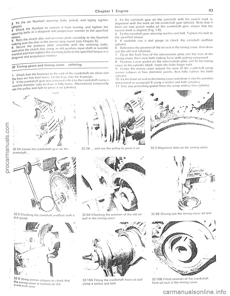
4 Chock the secur ing boilS
flywheel 10 "'~1'.111' ,I fro", tll,nlll\J. <1nd tighlen Ihe in il (li<1110I1ill <111(1 plO!i'''~~''VU l11<1ntJer 10 the speclf,ed
IOf~:iil l he clutch (Iosf: ilnd p"'~"'l"" pl.rle iI~s"mbly 10 Ihe flywheel 5 . ,ure Ihe disc ,s I he co"",:1 w.,y lo"nd (see Ch<1plor 5) rTlJk,ng . 6 Secure the pr~ssum pl"h~ "~~I:mhly Wllh the ,ct.1U1Ing boIlS. enl'Jlise Ille clulch dISC "Sill\) .11' old !i,,,"I>OX ,npul slwh 0' sul\ahle ~1Jnd,el Jnd thel1llghten Ih,~ ",I""'II1(II,,,IIS to Ihe sp~clfl()d tOlque III
32 TiOling geMS ilild li,nin(1 COVIH refitting
I Check Ih
';
. ,
. -\.
...
I't'
3 hI Ih'~ c,"n~h
,111(I'"nOIlI with the mark on tho cr,ll1bh.1ft HO
(1'1",1") 10 1 " 1 11,,, f'''111 n,l ~(, .. I tn the 11111111(j .:ov"r .111tl .haw 01 11,10 lh" 1'()~'IIOI\ ,h.I""))II,,,
~ ..
:U 'lA Loc"lo the cr,lnksh<1fl U", II 01 111" e ,.",hhilh
322B ,. ,HId uSO Ihc pull"y In pruss It on 323 Alryn"".",t d01S 0" lhu III\lII1~) \le
~ .. ,
..,
, ,
., ' ,
32 .61 Checklllg Ihe pOS,I'Oli of Ihu old 0,1 se
32 6B OflVII1!j 0111 the ""'lIlg COV(:r 0,1 se<11
32. 10B F,tluU posItion o f Ihe e
procarmanuals.com
Page 51 of 205
\.
50 C hapter 1 Engine
51 T llp pcts -removat
Remove the 1
5 2 Crnnksh
4 Wilhdraw Ih~ Wood'uH key hom the end of th(! CllInk5hah and pl,lC,(! " w'lh Ihe pulley. til(! holl alld its washer 5 The C'.1nk~h;)h p"lIey m;oy he ICliloved wilh Ihe eno,,,e III Ihe C:\I. hilt ,I 'S IIIsl tU!Ccss;o,y 10 ,emove Ihe ',ld'illO' :lI1d thc rh'vehelts
53 Flyw heel -remov[ll
P,even llhe flywhcel hum 101m",!) by FHlHllln\J Ihe lin!) !lcal ;ollain~1 ;In imp.ovised SIOI). 2 On nlodels willi nl;lnu:ol 1I;o"$""S5'01i. Icmove Ihe Clulch plessure 1)1;lle and disc :os described in Ch:op!Cr 5. 3 Rele.lse Ihe s,~ bolts secu.in!1 Ihe flywheel 10 Ihe CllInksh;oll .lnd lefl\OVC I,ve of Ihenl.
4 Whilc supporling Ihe tJywheel III pl;ll':e .• emove Ihc Sixlh hoi' ,'11d Iolt Ihe lIywheel otl c;o,elully. so 111:01 Ihe m;lllllg su.lilccs of flywheel [lild c.;onksh;oit ;o.e 1101 dllm,'ged
5 4 Sump -removal
W"h lhe '''1(1'''') oul fli the e,". CII~"'C Ihal Ihe sump has 1o('CIl d,amvd ;ond then lilln the engll1C ()VCI so tl1011 Ihe sump's U l)I)ClmOSI F" wOOr1CII bloc"s tn Slll)lmrl tim en!l'ne 'n Ih,s POSIIiOIl . 2 Remove 11m h()IIS seCUlln( J the oil Sump 10 Ihe CI.1nkColSe o1nd rClllOVO Ihe SUll1p_ 11 the sump IS stuck 10 the c r;ollkcasc . II should be reh;lIsctl hy 1"'SII1\1 olle SIde wllh 11 sClcw drover. 3 To !Cn,ovtl .Ile sump wllh Ihc CIIU"HJ Hl tloe eM. 11151 IcnlUVC Ihe
d'l)S llck :ond d'SCOIlII(!Ct Ihe hatlery 4 Remove Ihe luur holts ;ond lou. Ch,)S ;ond dCI.leh Ihe OIl splash
shIeld.
5 Pl;oce a Con'"lIlcr 01 at lellst 6lttre (106 JlIllI) cal,,-.elly heneath Ihe SUml). remove Ihe d,ain pl\l(l ;ond d,aln Iha sump. Reflilhe d.am plull and (11)hlen II 10 Ihe 10lqUO wrench seilIng gtven In the SIXlClflC;JIIons G Del:och the engme fubl)CI mounllngs, by lemovlng the" nuts an(1 w:oshe!s. 7 Romove the ciampinI) bolt hom the tal) ;oml bOIlOI11 endS 01 the Steellll!.) intellnediate sh(lil. rush Ihe lap end 0 1 Ihe shlilt upwollds unlll Ihe lowcr ell(1 Clin be dlsenga\led 8 PI
55 FrOllt cover -removlll
If Ihe engHle IS In the CM. II wllllnSI he necessaly 10 dlsc()nneC lthe l!allefY. drll'" 11m coolll1\) sys tem ;ond lel110lle Iho radiillor. 2 loosen the alternalol mounllrlg bOilS. SWlrlg the aitemalor downwilids .0w:Olds the cyltnder block and lemove Ihe drive belt
3 Remove the bolt Irom the cenlro of Ihe cooling Ian .. nd pull (
Ian and clutch assembly. 4 Remove Ihc boil an d wilsher from Ihe centre of the cran pulley .. nd I hen use ., claw puller 10 drilw Ihe I)ulley ofllhe sha nOI anempllO lelle, Ihe pulley ott. t)Ccause Ihis may .esull in dllm. t he Irani covcr.
5 Rcmove the si~ bolts secuung Ihe sump 1 0 Ihe honl cover an, t he cleven bolts securing Ihe I ront cover 10 the Cylllldcl block . G lIlt Ihe cover ott ;ond remove Ihe g;oskel.
5 6 Tillling gears -relllov;ol
1 Remove the honl cover 10 e xpose Ihe IImlnu ueo1/S 2 Removc Ihe bolt and washer sccu"I1IJ Ihe fat!Je gear I,
cn,nsIl1'll t. IhCIi pull.he geill ol! and Icmovc tho Woodllll! key. 3 Dlllw the ileal hOI11 Ihe cr;onk!;h:oh am! remove Ihe Wood'utl
57 Carllshaft -r erllov;ol
The camsh:olt nwy be rCUlovfld wllh the cll!JlIle 1<1 Ihe car •• lollowlng p!Cpol.aloIY wo,k IS co1med out. 2 0,,,,,. Ihe cootong syStelll nnd .emove Ihe .ad,mOl 3 Dlsconneci the ballery. 1 Remove Iho sp.1lk pili!! IC.1ds 1,om Ihe spalk 11lugs. 5 D,s':Ol
eCI the le;ods I,ull' Ihe :l lt'!11\.110r. remove Ihc allelllalo·
l i S (hivebell. G Undo "nd rem ovC tho screws S()CIIIII1U Ihe .0dcl covers and It Ihe rocke. covels and Iheir ilaskcls 7 Sincken lhe nulS secullnu the rocker ~"ns unlollhe locke' arm, he swung aside . 8 Remove the pushrods. idenlllylllg each one as .. IS lemoved. so 1 Ciln be rell1l ed in Ihe same position 9 Remove the cylmde. heads,
58 O il pump -r e m oval
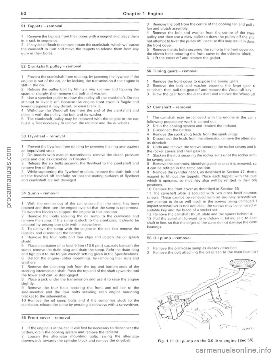
Remove Ihe crill1kc:ose sump as ;olleady dcsc"hed 1 2 Remove Ihe boll aUJchmg the 011 scrcen 10 the Illalll 00111.119 (
/ /
Fig. 1.11 Oil pump o n tho 3.0 f itre efluill(l (Se c 58)
F
procarmanuals.com
Page 82 of 205
Chapter 3 Fuel and exhilust sys tems 81
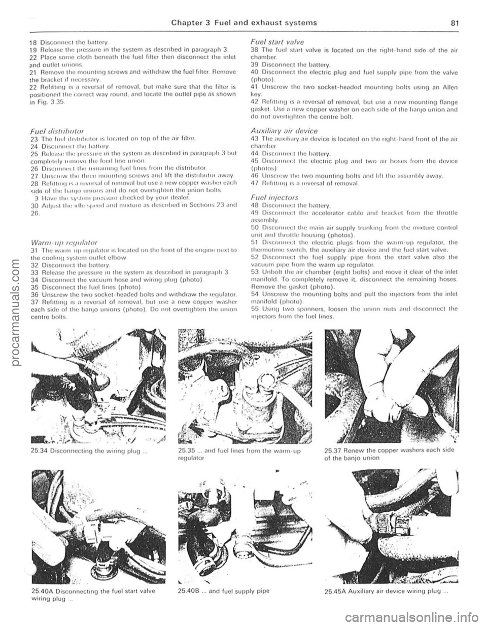
1 8 Disco"nect the hllllmy 1 9 Relc,,~e tl", .. ,e5~II.e In t he system "s described in palaglaph 3 22 P lace some cluth hcnc,llh the luel flhel then disconnect the mlet ilnd outlet ", lions 2 1 Rcmollc tht) mOIlI1lIlI11 sc.cws ,1od withl1,,,w Lhe fuel f,ltc ,. Remove
the bl:lclwt II 'ltICIlS$:I'y 22 RchulI1U IS a .ellcls:l1 01 ,emoval. but m"ke sure tha t the 1,ltel is
pQs. t.onnd thll I:Olfe ct W,ly 10un(l. "n(1 Locate tile OUIICI plj'JC:I~ snown
io FiH. 33!)
Fucl tlisfllbu{(}r 23 The f""t d'~L"I"'lor .~ IOr.i'to(1 on top 0 1 the "" flltl'!'. 24 DISCOnl"" .t thu !o:m",y 25 n,;L""~,,, thO! L''''',~II''~ III (hI'! system:ls d"sl:"lmd in piull u,a"h :I"" t compL"L"ly 11,111"11" tho I,,,, d 111111 ",Hon 26 DI~r."'UII". t tl,,, """,11'1'1111 f,,(:II'"C$ 1,<)ul til(! llis t,d,utOI 27 UIIS'~":W ,I", nll"l1 """m'"'n sc",ws alld hit Ihe IIISIIIIJlIIOI away 28 RHhll""1 ".,' ",v':I~,,1 "I rr""OvilIIJlJ IIISC a IIIiW coppe, w"~.h,,, r:ach ~,de of Iht: '1',"'1" IIIIIW'~ ",,(I dO not OVf!rI'UII1I:rllhe llIliol Imils 9 Hall" Ih" :.y·.1t:1I1 I""",u'li t: heckr.d by yo"r dllatCr: 30 I\dl"~t th" "II" "I~:I"t :II\l IIIHXIIlIfl as ,leScII",,1I III SectIons 73 ,IIld 26.
W"",,·/I/I/I.'ylll;/fOf 31 The w."'" "I' "'!I"I"tl1l 's loc ;llt,d on till! hunt of the ""!I"'" ""xtlO t he c(X,l"'H ~y~t"l11 nuth, t I:lhow 32 D,sco",,, • .: ! tl", lhlllCI" 33 Flcleasc Ihe prcssllfc In the sySlcm as desc"hed in parag'''I)h 3 34 Discount: GI Ihc lIacuum hose ilud wi"uy plllg (photo) 35 D'SCOI1"I:CI the fuel hiles (l)holO) 36 Unsc,ew the Iwo sockcl·he;lded uolts ;lnll wllhd';lw thll 'C!jUI;ltol . 37 Ref,(lln\1 IS ,1 ,cve.sa' o t ,emOIl"' . hut lise a new copp .. " wa~hcr eilch Si(lc 01 tim h,ll1l0 \llllons (phOIO) 00 nOl ove,l>ghtcil lh" I"'''on cenlre hol ts
Fuel S f"ff v:llvc 38 T hc luel stMI 1I:llve is located on thc ligl1l ·hand s,de of the lIir ch"mhel. 39 DIsconnect the bmlory . 40 Disconnect the elcctlic p lug and fuel supply pipc from th e lIalve (pholo) 41 Unscrew tho twO socke t·headed mount,ng bolts uSlllg an Allen
key .
42 Ref,,,,,,!) IS .1 'ellcrS:l1 of ,ernOllal. but u~e II ncw moullting flange !lasket Use" new copper w"shel all each SIde of the """10 union lind do nOI ovnlllllhien the Centrc holt.
A!lxih~1I"Y "i,. r/(!vicc 1\3 Thc i",x,h.n y "" rlcvice is 10C"II,1I On the IIU"t hal1d flOllI of thu lIir cha",!,,", 1\4 O lsc0I1"", .1 Ihe hallerI'. 1\5 D.scr"'''.,ct tl,(, eleCt,ic p l11\1 ;,ml IWO illf hoses IrOI11 the ""vice (phoIOS) 116 Unsc",w tl", two 'UO"nIl119 holts .11,,1 hit tl"l ;rss",,,t,ly i!Wlly. 1 7 Fl"f,It'''H .s ;1 HIIIC,s,,1 of 'elllolllli
Foel injocrurs 48 D, sclI"""'.t Ihe h;lll",y. 1\9 O, sr.
25 .4 0 A DisconnectIng Iho tuel slart valve
wiring plug
, "-
2 5 .4 06 ... and fuel supply pipe
•
25.4 5A Au xilia,y air dcvice w ifin g plug.
procarmanuals.com
Page 83 of 205
,
~ Chilpter 3 Fuel and exhaust systems
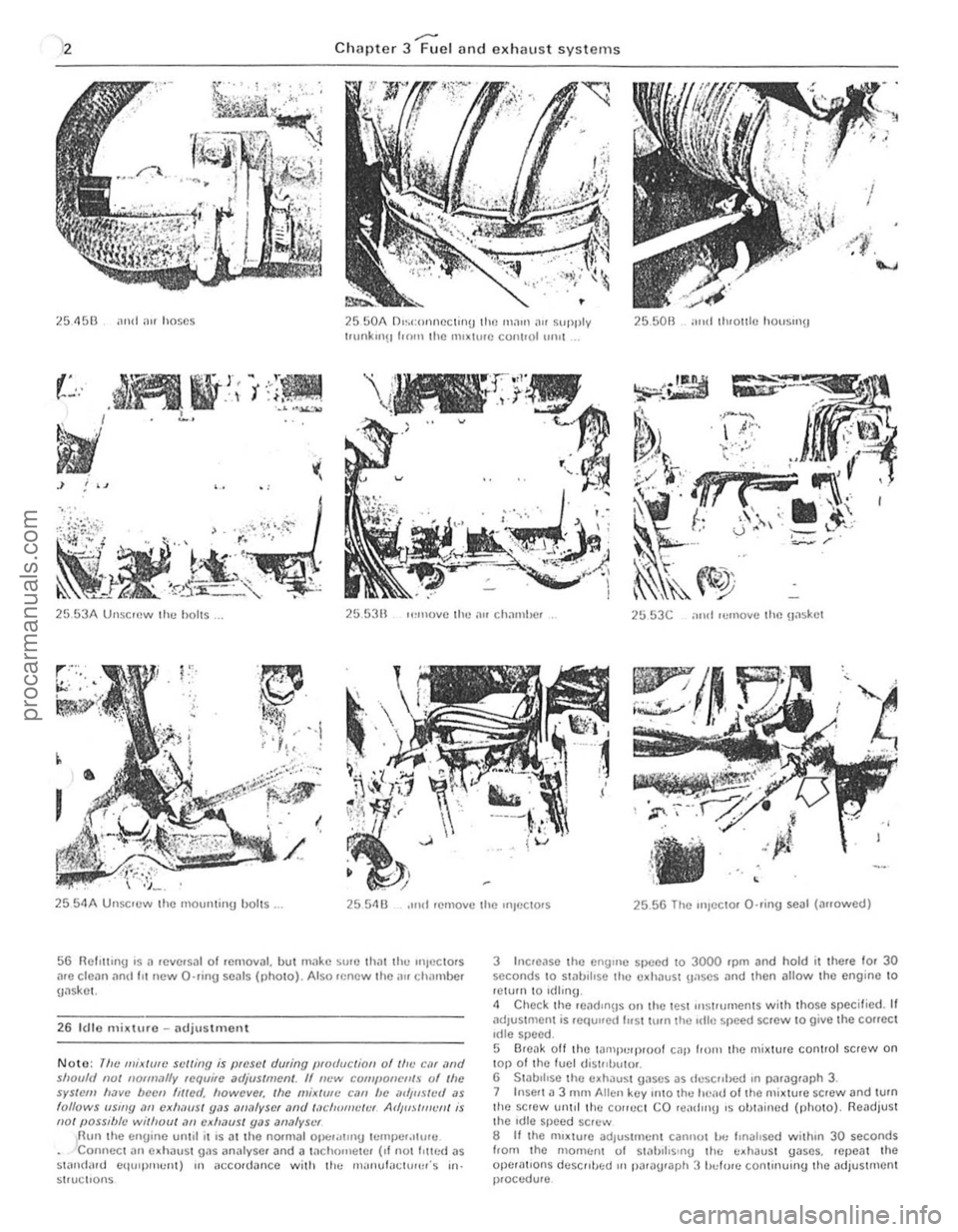
~5 4513 ,111<1 "'f hose s 2550A D",conneclinu the maUl "" supply t.unkul!! 1.011 the 1111~hue cont.ol 111111 25501l mid th'OI1I C houslIlU
"",'
25 53A UnsCII)w the holts. 255311 ,,,"U)IIC the ~'" chal11bcr ~5 53C ;11111 'cmoY(: the Haskct
,
25 5 4A UlIsc'ew the 11101l1lt;IIU bolts. 2554 U ,lIld remove the UIIL'CtOrs 2556 The "'Jecto, Q·rinU seal (a"owed)
56 Rcl,llll.g IS 11 reve rsal 01 rcmoval. hut mtlke SUiO Iha l til.., "l)OC Iors .IIC clea n and III new O'lIng seals (pholo). Also rencw the;IU chamber gtlskel.
26 I( H o mixture -adjustment
Noto: 11!e miJllllfe s"/liIl9 is preset during (!for/actiOIl of II", eM ,'nd shOll1ll 1101 "ofllwll~ require "djIISlment. If I!~'W r:QfIIl'O"Cllf.~ l)f 'he sys({)m ""VI! bccn flllCd. IlOwever. tile mix/IIII! (;,1/1 be mi,l/steil as lollows "Silly /II) cxlwlls/ y,l$
3 Incroase the enyulC speed 10 3000 'pm and hold it the,e 10' 30 seconds to Sl
5 Break oft the lalllpl:q)lOol cap 110111 the mj~ture conlrol screw on lap 01 Ihe fuel uistllbulOi. 6 S tabilise the cxhausl Ua ses as dcscllhc·d ,n paragraph 3. 7 In sert 11 3 r1\I AUcn key onto Ihe heau 01 the mixture SCfew and tum the SCfew urlld the COlfeCI CO re
procarmanuals.com
Page 93 of 205
![FORD CAPRI 1974 Workshop Manual Chapte r 4 Ig nitio n sys te m
6,SA Unsc rew the clamp bolt, 680 ... and remove the (tistJlbu to. 68C Rotor nnn alignmen t ;]lter re movnl Irorn engine
~ I
~.
F ig . 4.3 IU "i\iol1 timinu ma FORD CAPRI 1974 Workshop Manual Chapte r 4 Ig nitio n sys te m
6,SA Unsc rew the clamp bolt, 680 ... and remove the (tistJlbu to. 68C Rotor nnn alignmen t ;]lter re movnl Irorn engine
~ I
~.
F ig . 4.3 IU "i\iol1 timinu ma](/img/11/56932/w960_56932-92.png)
Chapte r 4 Ig nitio n sys te m
6,SA Unsc rew the clamp bolt, 680 ... and remove the (tistJlbu to. 68C Rotor nnn alignmen t ;]lter re movnl Irorn engine
~ I
~.
F ig . 4.3 IU "i\iol1 timinu ma,ks o n the 3,0 lit.e e:1Uine (Sec 6)
Allow ;//(lic<1leS din'cliu" 0' !(JIM;oll
7 Distributor (3.0 litre engine) -overhaul
W,th the diMJlhuto. removed from the entl,ne. 'emove the rotor arm and the cont.1CI breaker assembly . 2 Prose Ihe small Clfclll} I'om the v"cuum u,,,t p,vo l IXJSt. 3 flemove th e two sc,ews wh,ch sucure the hfllaker pl,lI!! to Ihe d,slJlbu tor body and hit the ,}I'rte orl.
" Slacken Ihe self'lappmg SCfew which SC<:UlCS the condense, and low tenSion leads 10 Ihe contact l .. eaker a ssembly and shde OUI Ihe lo.ked ca ble terminations, 5 Undo imd remove Ihe condenser rCI.1,nlfl!.l screw and remove the condense •. 6 Remove the c" chp. lIiJt washer and wavy wash er from the pivot post. Se parat e the two plates by h,ingmu the holding down se,ew Ihrough Ihe keyhole sial in Ihe lowe. 1)late , Ta ke care not 10 lose the e.Jrt h spring on the prvo t flOst. 7 Remove the two se,ews seeu"n\) Ihe vilCuum un,t to the d IS t"lHIIO' hotly .Jntl remove the vacuum uni t. S To d,snl.JllIle Ihe vacuum unll, remove the plug I.om the end 01 the
unit (md withdraw the spring. vacuum stOp and shims 9 Oelo,e disll1<1ntling th e centJllugal .Jtlvance mech.Jnism. note thM th e tw O spri ngs arc d.lle.ent and ma,k them so th.Jtlh ey .Jre ref'tled in th ei r OJlgHlall}lilces . Remove the sp. ings. pJlse all the circ lil)S securong the cenlJlluga i weights. nl.J.k the weight s 10 'dent'fy their o"ginal positions and then remove them ,
1 0 M3
x - ------:::-.
z
y -
Fig . 4.4 Distrihutor lilting position on the 2.8litrc e ngine (Sec 6)
XX Re.1r "U;,.' of ellgmc yy V,1CI/(JIII flllil Mas Z = 0 '10 11/'
A Triggcr (lffll U Slillor l!fII!
whICh'S Ihen exposed Ilntl ,emove ,I L,lt all Ihe Ci"n and 1l(IV3ncc plJle ;Issemul y,
12 Do nOI .cmove t he d,stJluutor Sl)indle unless II 's necess.l'y to "1 a new ge.n. 0' S I)iJldle To remove Ihe uear . usc <1 IlUnch Ilnt! hJmmer t o dJlve outlhc lock P'" and Ihon pull tl)() !.Ic", frO'11 Ihe sprndle T"ke cn,e
1 0 rOIil'" ilny slums, 0' wllshe,s wh,ch fll.Jy be In led . W,t h the ueJ' lell'Ov\:(\. the sl)lIldle .Jsscmbly can be withd,awn hom the d ,s'Jlhu tor 13 Belore reassembhng. ca,elully clc.J1l the body 01 th e d,s lnbulOr and "II a s CO'llpo llent p"'ts. II th e sp,n(!ie has been .emoved. lulmenlC II w'lh e'lu",e oil h efor e ,ellssemhly. 14 Reassenlbly.s <1 SUa'ghtIOrw<1Jd ,eve'SilI 01 d,sman tling bUI t he,e Inc several pointS which shoold be noted.
15 Lut)JJc;]te th e ce Jltlil ugnl weights and otho. p3rtS ol the cenlrifugal
advnnce mechanism. the diSlrrbutor shah a nd Ihe pa'l 01 the spindle wh,eh c.l"'es Ihe cam assembly. using engine all. Do not orl excess,vely. 16 " Ih e dr'veshnlt hilS heen .emoved. firSt re fi t th e thru st wash ers below tho action plnte. bolore "'se,ting the S h .l h into thc disl. ih llto,
hody . FII the w3vy washer .Jnd IhrUSI washcr to the lowe! end 01 the shah and then relilthe ge.Jr. secuJlnU it with a new spring p in. II a now gear. or a ne w u"ves hnfL h,15 been fllt ed . a n\lW hole should be d"lIed .1t 90' 1 0 Ihe e~is'U1g hole 17 Alte • .Jssemhhng the centJll ug.J 1 weIgh ts .Jnd sprrngs. check that Ihl!Y movo hccly. w,thout I)inding, 18 8clOle assemblmg Ihe breaker pla tcs . make sure thill the three nylon bearing slUds a.e located "1 tht) h oles ,n the uPllC' uearinU plale and Ih3tthe e.Jrth,ng sprrng ,s foiled to the p,vOt post 19 On complet'on of assemlJly. adlust the conlnCl b'eake , gilp to the spc cified selling
procarmanuals.com
Page 105 of 205
104 Chapter 6 Manual g earbox and autom ati c transmission )
PART 1, MANUAL GEARBOX
Gener"l description
The nl
At the "It,,"v
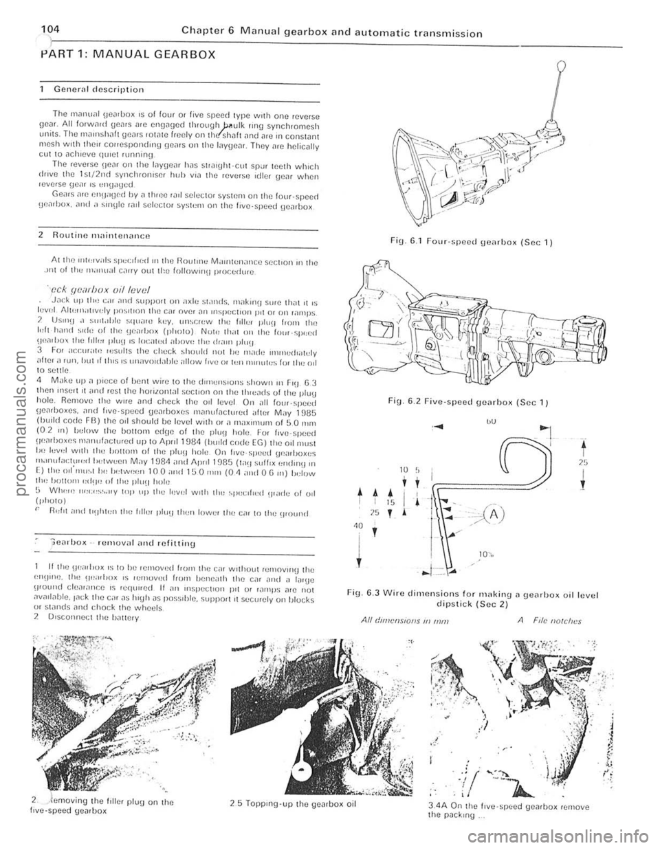
J.1ck up th,! C;lr amI SUPpO'{ on a xle s!;lIlds. m;lklll\j sure lh"lll 'S levI,1 Alt""l.ltlvely PO~III()n Ihe Cill over .111 "lsfH:r.IIUIl I"l 01 on lamps
) US"'~J ,I s\III, II,le SqLl,lIU key. un~r:",w IllI< hiler pili" f'O'l1 Ilw Idt h;1I1d ~I(h, of Ih(, oe"rI)Ox (pholo) Not" Ihm Oil Ihc lo"r-sp<:ed 11".101)0 the hll", ph,O IS 101:
\Jearhoxes . ,11l(1 f,ve·speed ge.1rhoxes m.1nufactlltud ,,(w, M"y 191;1S (!wlld code FIl) the 011 should be level with (]I a milx"num of 5 0 111111 (02 Ill) helow Ihe iJottOIll edne of the ph)~J hole. I: or ('ve-speed !1(;"'IJ()XI!~ m;lIlufactured liP t o Ap,,1 1984 (Iwlld co(ie EG) Ihe 011 "'list I,,, I"v'" W ill, 11,,; bOllom of Ihe plUH hoi" On I,ve· speed Ilca,hox cs "h"nda<:tu,,,,II,(,twe,)Il M"y 198<1 ,IIld 1\.11111 1985 (Iall sulf,x (,n(iIlHI II'
E) the o'("ltI~1 h" ""'w""" 1 0 0 ""d 150 """ (0 <1 alld 0 G 'n) 1,,;low 110" I)()UDl Il "d~I'! of Ihe I'lu~1 hoi,!
G WI",,,! "'";"s~.,,y top "I' l h " lev,,! with II", ~1'(!<:I(oed !jI;I(),., 0 1 001 (phulo)
" n,,(ot and "!Ih,,,n Ihn fill", plu!) Ihen lowe, Ihe "II to lloe ~)lolllHf
-;;e.1l'lJox -rmll()val ancl .efiuinu
If the IJ"ilrl,ox IS to he 'emov"d from Ih e Cill wllhcHJI romovlIIU Ihe ""II"l(J, Ih" !1'''"j,UX IS rumov,!d Irom heneallo lloe car Jnd il (,IIUe wound cle.11
Fig. 6,1 four-spoed \Joarhox (Sec 1)
Fi\J. 6,2 Five-speed !Jcarhox (Sec 1)
I.e , ..
-~
t 25 W II I !
t A • I I I 15 I
7 (11) no I I ~
~-
" I /
~ 10\,
· ... 1--=" ...
Fig. 6 .3 Wire dimensions for IlHlking a geilrhox oil level dipstick (Sec 2)
All dUllet/SIOIIS J/l IIUn A File lIole/n's
:; .
.. ~ .. -,.' . • <
! ,,;
'r '
,j/
' I
live-speed 25 TopP lng'up the gearbox oil 3 ,4 A On the lIve -spee d UOilfhox remove the pack,n g
procarmanuals.com
Page 107 of 205
·06 Chapter 6 Manual gearbox and automatic transmiss io n
disengilge the gearbox inpu t Shill! hom ,ho clutch p,Iot bearing ,111(1 clu tc h friction disc. I, is imporlanllhal,hc engine and transmi ssion <'lre kept in lino while this is being done. 14 When the gearbox shaft is cleDr of the clutch, remove th e
tran smissio n assembly from bCn(!illh the car.
15 When refiuing, ensure 1il1 the clut ch pilot h earing in the end althe tfilnksha h is ill plilce Jncl is scrviceDble. Tic the clutch lever 10 the clutch housing, 1 0 pr(!venllhe release le.rertrolll slipping out while the ,Wnsmission assembly is being lined. 16 Smear some molybdenum-based grease OntO the end and splines 0' the gearbox input s!mh lind refit the gearbox by reversing the fcmovili p.ocedure. 17 II is impO.IMll when offering up the {jOMOO)(. th,lt il is e~
slightly until the splines enter Do not iluempltO lo.ce the tfilllsmisslOn
ontO thO enlJlnO ThiS Illay (i
'8 Ahe •• el,uinn has been completed. chuck the 011 level Ifl t he .r
Romoye the lou. bolts hom the 1011 cove. 01 the t.ansm.sslon c~t()"sion housin!J ilnd f.om the lri"'snHs~ir)Ol eo'S<' Ilcmovflthc \:oye. s.
t.1king c
R emoYo the .eyerse idle , shah by sc.ewing a suitable bolt into Ihe end of Iho shah and then leye.ing the Sh;'lit Out uSing Iw o open ·ended spanne.s. Fi\)
.
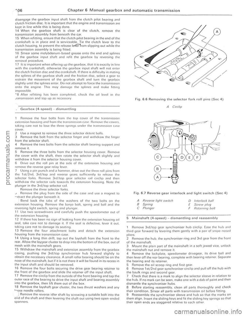
6.6 Removing the seleclor 10lk rolillins (Sec 4)
A CIfC/'11
Fin. 6 .7 Revorso gear interlock nnd light swil c h (Sec 11)
A Ravelse liyh, switch 8 Swing C Plf/ngcr
o h!/ellocl< ball E Sc,ew IJlug
Rct.1ininy bolt F
5 M
thud gear lotwald lly lel/erinu the,n gently wrth a p
their condition. Smear all Pi/ItS wilh tr3nsmission 011 befo.e fitting .
9 Reassemble the synchroniser sleeve and hub so that the nlafks on thorn align . Inse.t the sliding keys and 1IIIhe shdrn\) key sp"ngs so Ihat Ihei. open ends afe stagge.ed re lat ive 10 each other
procarmanuals.com
Page 111 of 205
~10 Chap ter 6 Manual gearbo)( an d automatic transm iss io n
operlltlon. looseness between the inner ;mel oulC. ';)ces. imd 10f genera' wear. NOfIll.llly they should be .enewed on a gearbox lh<11 IS being .ebuil l. 8 II Clther 0' the synchrOnise. unllS ;nc WOUl II w Ill be ncccssmy 10 buy" complete assembly as the Pill ts ,lIC not sold individually. Also check the sliding keys 10' we;'!. 9 Examine tho ends 0' IhO scl(!C I(ll' lor ks where they rub "g.1In51 the channels in the peJiphery of the synchrOntSfl f units_If I)()Ss,ble cOIllp.."e the sclecw. lorks with new Units to hell) dC1Crminc the weill lh,,1 h,IS occtJUcd Renew thelll " worn. 10 If the bCilring bUSh ,n Ihe CXI(mSlon is b;uliy worn II,s OOS110 [
When any hOlt screws "110 a throuUh hor". JOllll11\!J COlllpnulI/t Should hc nj)lllted to I he lhwads 011l11! holl helorc It ," InS/"h~1 2 Fit Ihe /cve.so Idle. He"r WIlli Ihc It,oolle on the !le;1I tuw;IId,. Ih,' lenr.lnsel! Ihe .dle, s h ah nnll dlllle 11111 with .1 pla~t.c·IIIl:IIIt].1 h;""""" unllllhc OOltOnl ollhe Slel) on the end ollhe shalt.s IIIIsh WIth lhl! ,,11.1 0 1 the gCJloox. Thc mIlled "
FlU. 6 13 Apply 101ll1lng compoullll to the threilds 0 1 Ihe bolts. lIl~e
0,1
the new IIlput sh,ll! ncedle rollel heilrlllg ilnd push I t 11)10 tllC oJorc 01 the input sha ft Slide the lOP gC(lr synchroniser baulk IInu on to the cone olthe IIlJ)u I sha h 8 FIt the extension houSll19 gnske!. lhen InSerl the ,1s~",hlcd mainsha/t into Ihe rca. 01 the box anll (frille II III untIl the nose 01 Ihe Illalnsh~h is fully engaucd in I he II1PUI shilh necdle l>c,l11nU 9 Carefully lu.n the ge;ubox upSIde down. so thilt the layshalt \}e,lr elusler dIOI)S mto engJgelllenl with the malnshillt Jnd IIlpIII shalt Check thilt the gear and the two lluust wilshe.s il.e III line and then c,l.elully push in the layshalt from thc leal. If necessary till) Ihe S h ,ll! In with the p lasuc·headed IHI/llmer. bllt take grC;lI CJre not to dlslodUe Ihe thruSI washels or needle .olle.s . When fully home. the h Ollom of Ihe slep on the .dlel shalt shOuld be In hnc with Ihe face 01 the box and Ihe mIlled flats should be in IIno wllh the Idler shalt oo.e. 10 Turn the geilrbo~ the lighl w;ly UI) Jnd align the hole in the 1>.111 bemll1g SUpj)Orl WIth the dowcl on Ihc cxtcnsion housing. Fit the eXlenSlon housing. Apply jOlllllnu coml)ound to the ttlle<1ds of Ihe bolts. InSClt them and tightcn 10 thO torQuc wrench seHlng gillen In the SpeCll l
C3tions . 11 1/ a new cxtension bush has been fllle(1. check Ih~t the notch 01 011 groolle III II ilhgns wllh lhe o ll,elurn grOOlle In thoJ extension housing. If thc now exlension housinU 011 senl hilS not illready been filled. slide It Ollel the extension Shill t and enrelully tap it in wilh n h~nllller and n
b lock 01 wood.
1 2 FIt J ncw O ·ring to the spcedomeler pll110n assembly. relit the ~Sembly and f it the C llcli l) to socure i1. ,3 Inser t the r(,lIerse gear interlock plungel. ball and spring. Fllihe boll with aloek plate and lIl$crl tI,c l.Iol t. TIghten the boll and bend Ihe lock plilles to seCure ,to
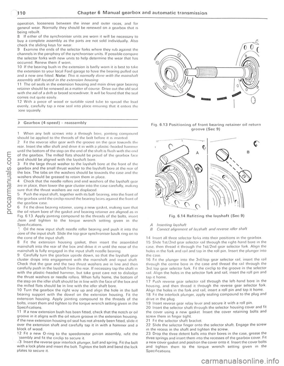
Fig. 6.1 3 Posilionin g of Iront hearin\} .e lainer oil return \}Ioove (Sec 9)
=-*.------t---.---- ---
FiU . 6.14 R olitting the Inyshaft (Sec 9 )
A hlSC//ing /,1vs/!I!f/ B ClJflec / lIi1:qlll!!efl/ of /,J)'$/I,III illld 'fJve.se IdlfJf sl!,lfl
1/1 Insert ~II Ihrce selecto, 10l~s Into Ihcn I)ositlons 111 lhe gearl)o~ 15 Shllc 1~1/2n(1 \le,1r selector ,,111 through Ihe r,ghl-hilll(1 bo.e mille
I:ilse. Ihell tluead ,t through the 1 S I/2nd gCM selector lo.k Align Ihe holes 111 tile lo.k and r~11 ,111(/ t<1l) in the 101l1)ln. Insert the plunUe/ into thc c,lse 16 FIt Ihe pltlllgc/ '1110 Iho 3rd /lOI) ge,ll selecto. lad. inscrt lhe 'illl
t h .ough Ihe ccnHe hore III the C,lse ;lnd Ihread the raIl Ihrough Ihe 3rd 101) gea. sel()(: tor lo.k. Fit the clfchp to Ihe groolle ;n the se lecta' lilll Ahon Ihe holcS III the selectol 100k and ,;lil. insert the loll pIn and lal) .t home. 17 PUSh lellerSC gc,'1 seleelo, r;llt Ih/ough Ihe lelt·hand bore in the hou$"'g. and then thread 11 through the rellerse gear seleclol fork. Align Ihe holes III Iho IOrk and 101.1. inserl a roll pin and tap it home. 18 FIt Ihe interlock plungC/< apply sealing compound to the plug and dfille In Ihe plug 19 Inse!! ICllerSe ueJI ,clay lever and secu/c it wilh a roll pin. 20 Inse't thO sCleCtOr shalt ItHough the selcctol housing COllel and fit the co~er using a new gaskel Insert the COlier rewining bolts and screw them in Iingel lIghl. 21 FII the sel/lCIO' sh:lh b'lIcket 22 Shdo lhe S(lIOClOr flnge. onto the selec tol shalt. Eng~gc the strew III the ,ece~~ in th O shaft ~nd tIghten the sc rew. 23 0101) lhe Ihloo dctent ba lls 1I1tO thcir bores in t he casc. g1Case the thleo sprinus alld Ilise rt thcm Into the recesses 01 tile yeJ.1>ox COllel. FII
a new COlier gasket and positIon Ihe COllcr onto II Insert the COllel holtS and tlghtcn Ihem to tho 10Ique wrench suiting (Jillen III lhO SpeClf,callons
procarmanuals.com