light FORD CAPRI 1974 User Guide
[x] Cancel search | Manufacturer: FORD, Model Year: 1974, Model line: CAPRI, Model: FORD CAPRI 1974Pages: 205, PDF Size: 43.75 MB
Page 106 of 205
) Chnpter 6 Manual gearbox ililel
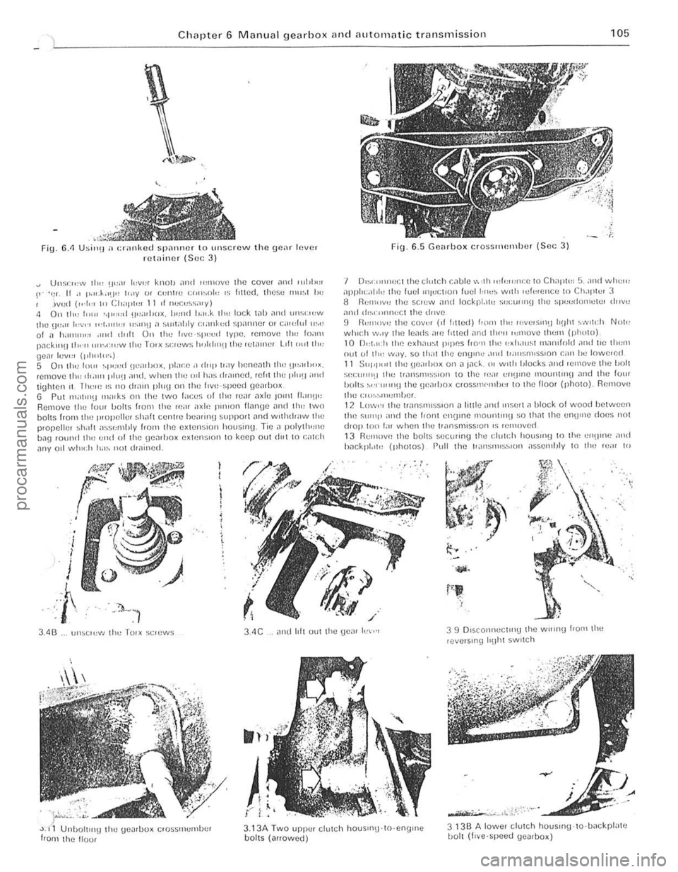
Fin. 6.<1 Usi",! a cranked spalliler to unscrew the goar Inver retainer (Sec 3)
Uus';",,,, 111" !I";)' '"'1''' knOiJ and ",lllOv,! 1he COVlJt
Fig. 6_5 Gearhox erossltH!lllhcr {Sc. ; 3)
'I 0,,,(I)I)I
:C1 the cl,,[r,h c
hn ekpl.,,!! (photos) Pull the ['.lI1SIlHS",OIl ;,sselllhly I() Ihn 'c;" 10
.,..
3.4C
).,
{" ; ",
3.13A Two upp.:. cllllCh houSIIlU-lO·engrne boilS (arrowed)
3 13B A lowe, clutch houslflg-lo·hackpl"te I)olt (I,ve'speed (JeJrbox)
procarmanuals.com
Page 107 of 205
·06 Chapter 6 Manual gearbox and automatic transmiss io n
disengilge the gearbox inpu t Shill! hom ,ho clutch p,Iot bearing ,111(1 clu tc h friction disc. I, is imporlanllhal,hc engine and transmi ssion <'lre kept in lino while this is being done. 14 When the gearbox shaft is cleDr of the clutch, remove th e
tran smissio n assembly from bCn(!illh the car.
15 When refiuing, ensure 1il1 the clut ch pilot h earing in the end althe tfilnksha h is ill plilce Jncl is scrviceDble. Tic the clutch lever 10 the clutch housing, 1 0 pr(!venllhe release le.rertrolll slipping out while the ,Wnsmission assembly is being lined. 16 Smear some molybdenum-based grease OntO the end and splines 0' the gearbox input s!mh lind refit the gearbox by reversing the fcmovili p.ocedure. 17 II is impO.IMll when offering up the {jOMOO)(. th,lt il is e~
slightly until the splines enter Do not iluempltO lo.ce the tfilllsmisslOn
ontO thO enlJlnO ThiS Illay (i
'8 Ahe •• el,uinn has been completed. chuck the 011 level Ifl t he .r
Romoye the lou. bolts hom the 1011 cove. 01 the t.ansm.sslon c~t()"sion housin!J ilnd f.om the lri"'snHs~ir)Ol eo'S<' Ilcmovflthc \:oye. s.
t.1king c
R emoYo the .eyerse idle , shah by sc.ewing a suitable bolt into Ihe end of Iho shah and then leye.ing the Sh;'lit Out uSing Iw o open ·ended spanne.s. Fi\)
.
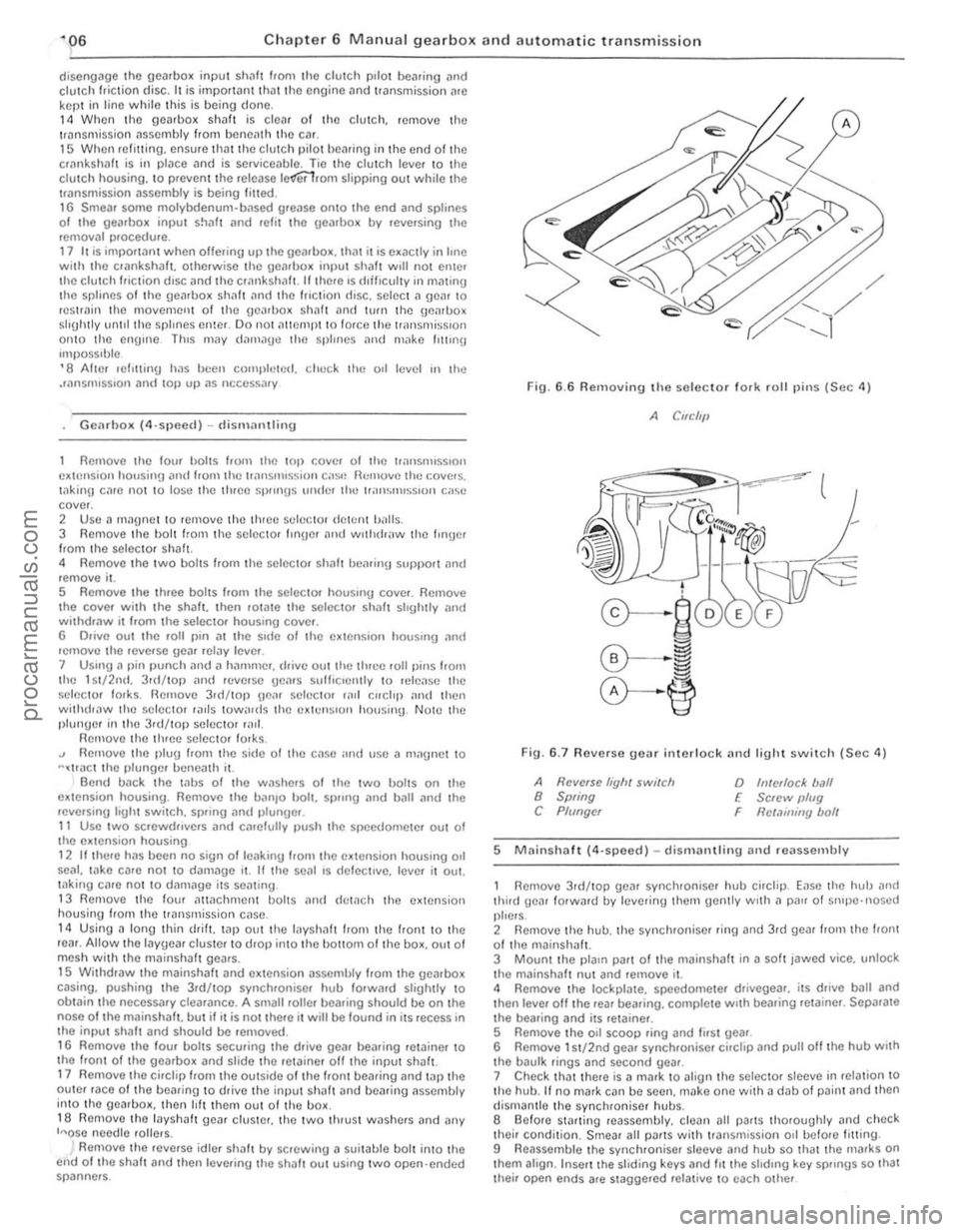
6.6 Removing the seleclor 10lk rolillins (Sec 4)
A CIfC/'11
Fin. 6 .7 Revorso gear interlock nnd light swil c h (Sec 11)
A Ravelse liyh, switch 8 Swing C Plf/ngcr
o h!/ellocl< ball E Sc,ew IJlug
Rct.1ininy bolt F
5 M
thud gear lotwald lly lel/erinu the,n gently wrth a p
their condition. Smear all Pi/ItS wilh tr3nsmission 011 befo.e fitting .
9 Reassemble the synchroniser sleeve and hub so that the nlafks on thorn align . Inse.t the sliding keys and 1IIIhe shdrn\) key sp"ngs so Ihat Ihei. open ends afe stagge.ed re lat ive 10 each other
procarmanuals.com
Page 108 of 205
~
~ ,
~"i
~' .2
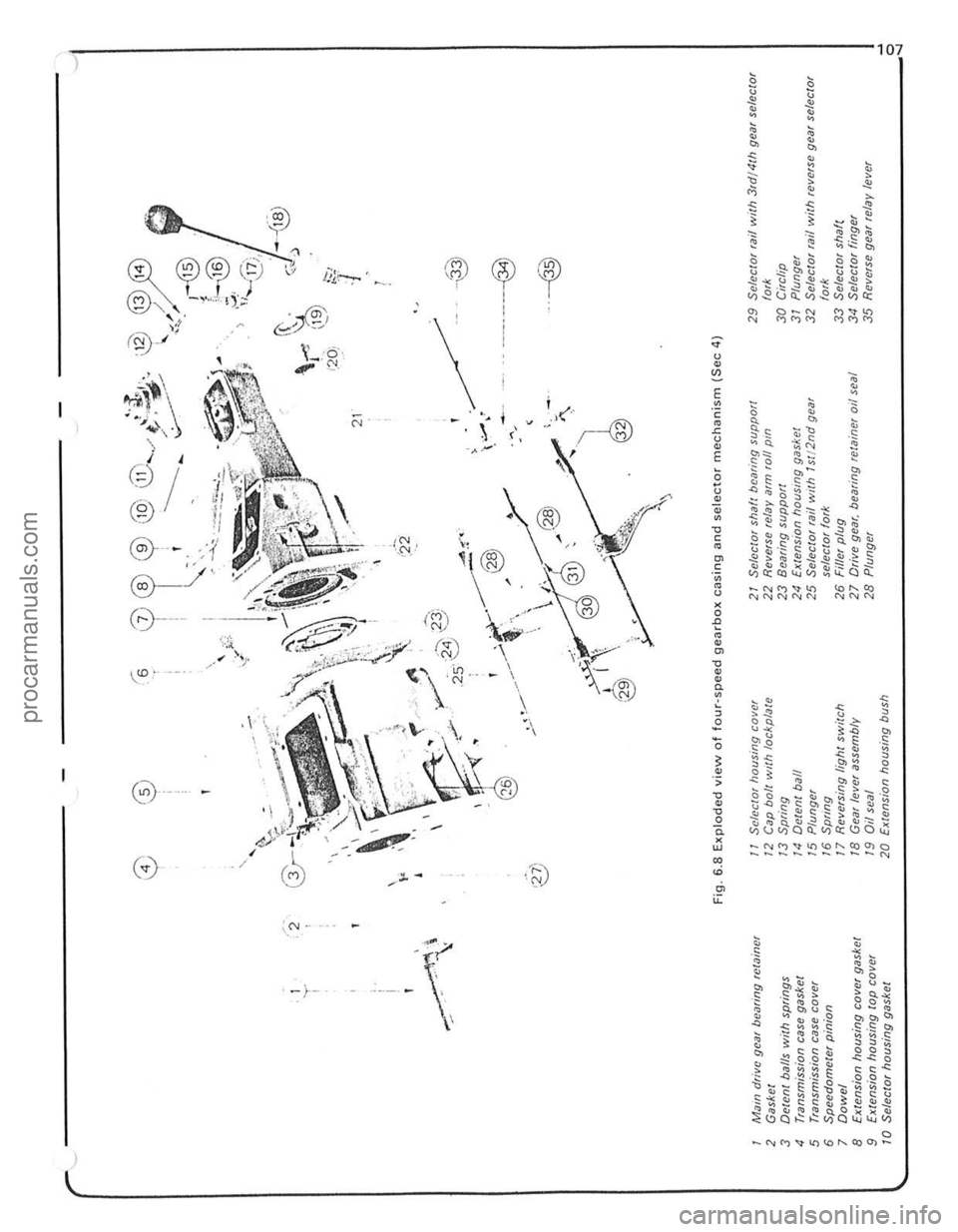
, Mil'" dfivc gear bearing fewincr 2 Gasket 3 Detent balls with springs 4 Transmission case gasket 5 Tfimsmission case cover 6 Speedometer pinion 7 Dowel 8 Extension housing cove! gasket 9 Ex/ension housing lOP cover 10 Selector housing gasket
0) ® (6 o I , ,
, i
"' t:< '
I , - \.f' -
(t!
,Wi 1m '~f" .'-../ '---" .... ......-t ' , ..
-----~:.---~
@@y314 , /
'" '". I-@
< i~@ -. .-.J.'
"...J\7' "'-', " . -,-;. , '\. .. ' --..,
~ .o.--? 0, .' '-;, ;:-~ \"'~. , . \~ .;; (3/--.,.~ ~1'\ . "~., . -,~" "~\_. \. ... " . , ~,
'i::
'r'" ~
F ·® (" ,J
J
I
- @
' \... . --; , >. ..~ . ./ j\,
' r<»., ~\ "":~" < ,
"
.. ..J ~, ' ...... .' ;". .~ . .-... ' ";:,;... '( , . -~ '23' " . I _./ _~,~ '.' _ .... JIi'"'"' •. ~ _",_ . ' ./.' 25' _ ..
; .. ' " .~'W
--<. .,y 'B Y ~ • --, 1 ":-'..., '~~ ,
<-.~ ~
ff,v ~30 ~ '.~, 32
@ < ,
. >
--®
1.20,
21 . ,
\< /22 , .
~" ; " "-,'
----@l . ' .
@
Fig. 6.8 Exploded view of four-speed gearbox casing and selector mechanism (Sec 4)
'I Selector housing cover 21 Selector shaft bearing support 29 Seleclor rail wilh 3,d/4th gear selec/or 12 Cap boll wllh lockplale 22 Reverse relay aIm foil pm fork
13 Spring 23 Bcaring sUPPOfl 30 Circlip
14 Delenl ball 24 Extension hOUSing gaSket 31 Plunger
15 Plunge! 25 Se/ecto! fail wllh 1st/2nd gear 32 SelCClor rail with reverse gear selec/or
16 Sprmg selector lork fork 17 Reversing light switch 26 Fiffer plug 33 Selector shaf( 18 Gear {ever assembly 27 Drive gear, bearing relainer 011 seal 34 Selector finger
19
Oil seal 28 Plunger 35 Reverse gear relay lever
20 E~tension housing bush
~'c:-.:cc::-:-.:c.:,.,· .. , . .... ,
~
~ 0 ~
灲潣慲浡湵慬献捯m
Page 112 of 205
Chapter 6 Manual gearbox and automatic transmiss ion 111
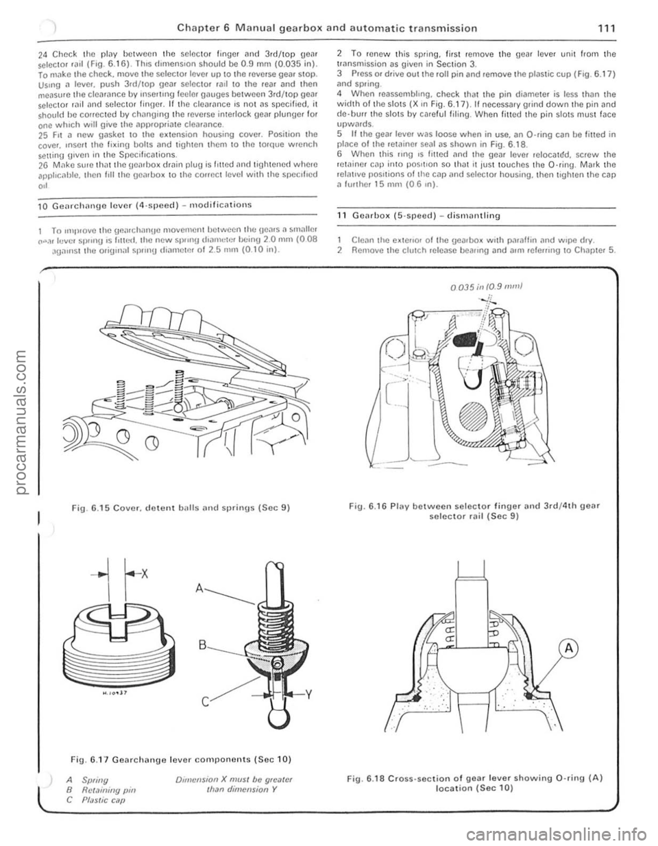
24 Chec k the plilY between the selector finger and 3.d/top geM selC{;lOr .a,1 (F,O. 6 .1 6) . lh,s d,mens,on shou ld be 0.9 mm (0.035 in). lo m"ke t he chec k. move the selec to. leve. up to the .everse gea. SlOp. Us.ng a lever. push 3.d/top gear selector .all \0 the rear and then
measure th e clea .ance by rnsel1lng leeler gauges betwee n 3rd/top gear selector rild "nd seleClOr finger. If th e cleM,mce 's no t ns specified. it shou ld he conecled by chnnging lhe .everse interlock geM plunger for one whIch will give the ,'PI).opria te clearance. 25 F,t a new gasket 10 the e~lension housing cover. Posilion the
cove •. ,nSOI I the fi~ing bolts nnd lighten Ihem 10 Ihe torque wrench Solt1inlJ g,ven in the Specifications. 26 M,1kc su, e th atthe geMl>o~ dmin plug is I,tted and tigh tened where apphc, 1hlc. then I,ll the uenlbo~ 10 the COffect level with the specl l'ed
,,'
10 Gcnrchnnge lever (4,sjleccl ) - m odificnlions
1 To ,mp,ovelhe \]flnr ch nngc movemcntlJctwecn lh(: Hea.s. , smallm CO".,r levcl Sl)!"'g ,s 1'lIr,<:I. the new 51)/,nU d,amclr'!' bc inU 20 mill (008 aga,nst the orig,n;r l sp.,n!) IIiarllctm 01 2.5 nUll (0 .1 0 inl.
Fig. 6 .15 Cover. d ewnt balls and sprinus (Sec 9)
Fig. 6.1 7 Gearchange lever components (Se c 10)
A Spliny B Rct.1illiny pin C Pf;JSlic C ilP
Dlillcnsion X mUSI be gloater Ilran dimension Y
2 To renew Ihis sp.ing. lir sl remove the gear lever unit from the trnnsmission as given in Section 3. 3 Press or drive out the roll pin and remove the plastic cup (F ig . 6.17 ) ;rnd spring .
4 When reassembhng. check that the pin di('!meter is less thiln the width 01 th e slots (X ,n Fig. 6.17), II necessary grind down the pin and
d e·llUrr the slots by ca.e ful filing . When filled the pin slotS mus t face upwMds. 5 If the gear leve. was loose when in use. an O-ring can be filled in placo o f Ihe retainer sOill as shown in Fig. 6.1 8 .
6 When this flng ,s fmed an(I the gear leve. reIOCalr:!d. screw the retainer cap inlO pos,tlon so th ilt It jus t touches th e O·ring . Mark the relntlve pOSitions of tile cap
1 Clean the e~tello. 01 Ihe gearbox w.th paraffin .,nd w.pe d.y. 2 Remove the clutch release beallng and allli lele",ng 10 Chapter 5.
0035;11 10.9 mill}
Fig. 6.16 Plav between selec to r finuer and 3rd/4th geM selector rail (Sec 9)
.. : . :,'. :", .
fLJ
··· ..
A
Fig. 6 .18 Cross· section of gear lever showing 0 ·rin9 (A) location (Sec 10)
i
i
procarmanuals.com
Page 115 of 205
Chapter 6 Manual g ea rbox and automatic transmission
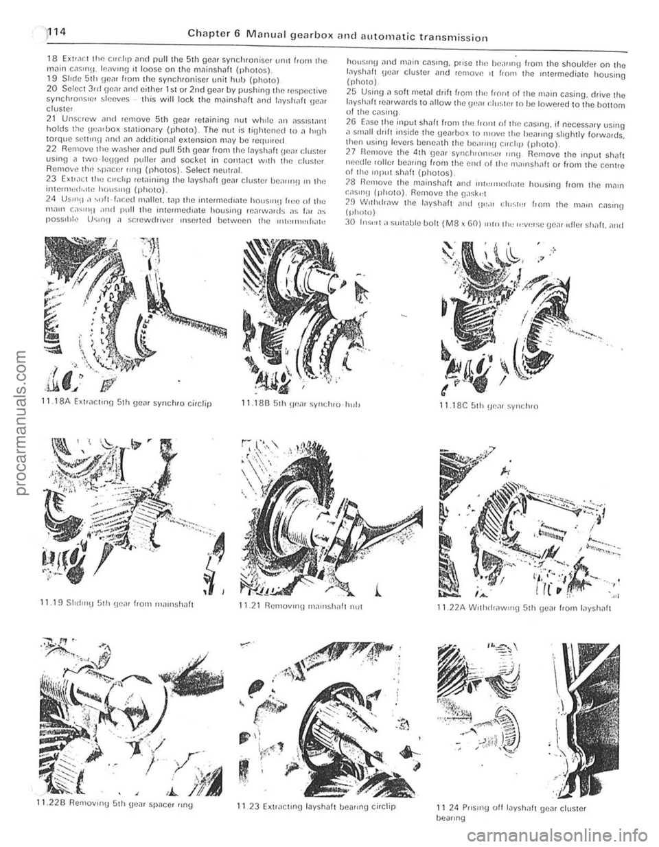
18 EXlra ct the r."dp and pull the 5th gcar synchronise r ur1lt f'orn the
rnn in c,lsm\1. Icavlllg I t loose on thtl mninshaft (photos). 19 S II(le 51h IlcM from the synchroniser unit huh {photo) 20 S elect 3rd gem and either 1st or 2nd gear by pushin\) the re~peclivc synchronsrcr sleeves this will lock the mainshllft
24 US"'(I;' ~oft·f;,r.ed Ill;-rllm. wp the intermedrate hOtJS"'~1 (,,!e of tl,,; ",<1111 c
.I,' ,i.li. J
hO(lSII1\1
layshilft rearwards to <11101'11 the \ .wm d,,~tn' t o he lowered 10 the hottoot 01 tlHl cas,,'U .
2G Ease tlte input Shaft f'om the frOllt 01 tlHl c;-rSlng, if oecess
29 Wllhdr,lW th e I,lyshalt ,11lel 0"_" eh";t,,, I,om Ihe 111<1111 C;-rSlIlg (phOlO)
30 In:;'''I; ' sUlwble bOl t (M8 x GO) Illto Ih" ,,,v',,:;c !Je,1( ,die, shnft. alld
11 18A Exlrar.t,nn 5th geM synchro ci,clip 11.18B 5th u em syl,(IHU hul) 11 18C 51h ~Je;-rr synclH O
11.19 SlId l"!J 5th !/tlar from "'
Page 122 of 205
) Chapter 6 Manual gearbox and automatic transmissio n
121
"
i
...,
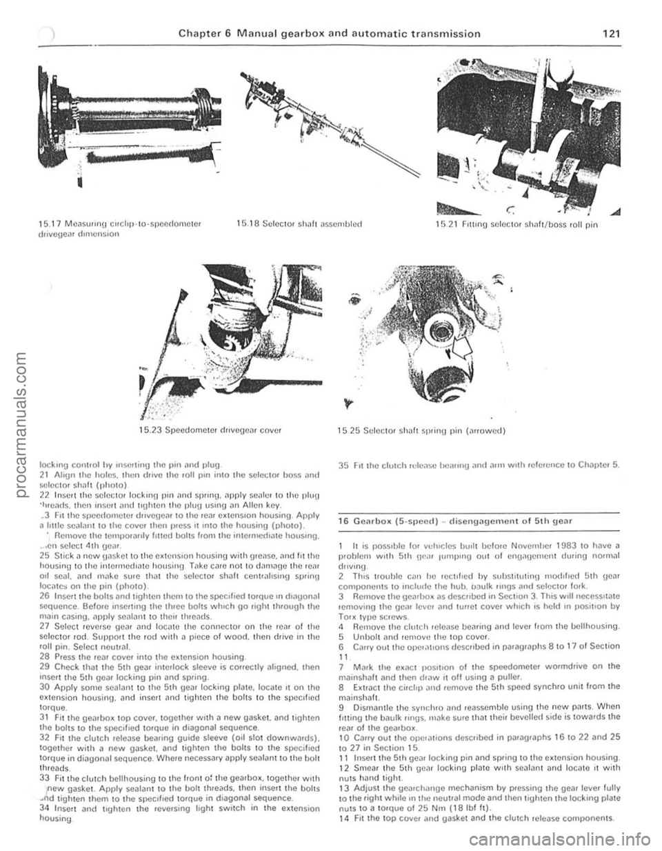
1 5. 17 MC~Sll"nu corchp· 10·SPCI1(lOIllClcr drivcgc,l' dImension 1 5 .1 8 Sc lcCl0f Sholl! t1sscmlJ lcct 1521 FIlling selector sh1lft/boss fall pin
15.23 Speedome ter dJlvcgcn, cove.
IOCkmg cOI1l,ol hy Inserl;"y the 1)111 ;lnd 1>lu9 2 1 Ahgn the holes. then (lillie Ihe roll pin il1lo the sc lcCIOf boss ;111\1 SI~ICC1Of s h
main c .. sing ... pply se
29 Check that the 5th gea. interlock slceve is corrcctly .11ognoo. then 'nscrt thc Sth geil' locking pin and spring.
30 Appl y some scalallt to the 5th geilr locking plate. 10Cilte It on thO extensio n housing. an d inselt nnd t igh ten th e bolts to I h e specIfIed torque. 31 Fit the Ueilrbo~ top covcr. together WIth a new gas\(et. and lighten
the boilS to t he sf1eclf.ed tOfQue in diagonal sequence. 32 F u the clulC h relCilSe bearing guide sleeve (oil slot dow nwllfd s). together with a new gilsket. and lighlen th o boi lS to the specillt~d torque in d;ilgon;11 sequence. Where neceSS;1ry apply seal,.nt to the bolt threads_ 33 Fitthe clutch bell housing to the Iron t 0: the gearhox. together woth new gaske t. Apply sealant to the bolt threads. thcn inse n the boilS .~d tigh ten them to Ihe SIXlcllled 10rQue in diagonal sequence. 34 Inscrt and trgh le n the .ev(usinl.l Ioght switch in Ihe ex tensio n housing
1525 Selec tor sh aft spring pin (arrowed)
35 FIt the clutch reLease l"l'lIIng and a.1Il wuh .efercnce 10 Chnl)\ el 5.
16 G e(lr box (5-spee{l) -d isellg i:lgem enl of 5th gear
I I
is possI ble 'or vducles hu,l t bclo.e NovcmiJer 1983 to have i:l p.oblem WIth 5th ne". Illillplllg Ollt of cnuanClllcn t during normal
(hlv lnu
2 ThiS 1I0uhle Cilll he rcc tl',cd hy suhstitutinu nlod,hc
3 Rem ove Ihe gearbo_ "s de$("bed in SectIon 3. This wrll nCCCSSlla te lemov ing the ge(l' Icvcr "nd lu"C I cove. whIch is held In ,)OSltlo n by TOOK typc sClews . 4 Removo the clutch Hlleilse bearing and tevcl 110m the bclthousing . 5 Unbolt ami lemovc the lOP covel. 6 C"ory out the opel,1t'0"S dcsc llbed in par "graphs 8 10 1" 01 Seclion
" 7 M"r\( Ihe ex.1Ct IIOS""o n of t he speedometcl wormdrive on the milinshil lt (lnd then draw it off using a pulter .
8 Extr"ct the ci. et,p "nd H)move the 5 th sp(lcd sync hro unil/rom Ihe
mJinsh"lt. 9 Dismanlle the synr.hro "nd reasscmble using the new p" rts, When I Itting t he b"ulk lings. m"ko sure that theil bevelle( 1 side is tOwa.ds the
re,,' o f Iho ge",box. 10 Caffy out the ope,,,,,ons desCfibed in jh"lfilgraphs 16 to 22 and 25 1027 in Section 15. 11 Inser t the 5 th ge
procarmanuals.com
Page 128 of 205
Chapter 6 Manual gearbox and automatic transmissio n 127
2 Select position O' th en pri$e off the selector level escutcheon nnd. Irom under th e cnr. re move the plug in the side 01 the selector housing. 3 Adjust the inhibito r cnble locknut X to giv e a dimension of 0.1 to 0.2 mm (0.004 to 0 .008 in) (Fig. 6 .36). 4 Refit the plug nnd escutcheon. S With the trnn smission shih lever and the mnnunl selector lever in '0'. ndJust th e selector rod link until it cnll be reconnected without strain .
23 Downshift cable -removal. refitting and adjustment
Support till! front o f th e cm on Jxle Sl
24
S lnrter inhibitor/reverse Inml) switch -removal and re fitting
1 Pull the cable connector off the switch" 2 Unscrew the slnrter inhihitor swilch and remove the a"int[ 3 To rel'llhe swilCh. fil a new a·ring nnd screw the switch into lhe housing longer. tight. T'gh ten Ihe switch 10 the lorque wrench settin g
given ,n the Specilicntions. I t is imporlnl11 ,hn t thiS torque is not excee dud, 4 Ro::I't the cnhle plug conn ector to the sw,tch,
5 Chuc k th,ll th e en!J"'c will st",t only w,th the lever '" the '1" and "N' posilions and in no other POSlt'on. S TlIIn 0 " the ignition without startll1g th e engine, Check IhM the
r ' ;inU light comes 0 11 in th e "R" po~rtlon, but not in any other.
25 .tension housing o il senl-renew,,1
1 Remove the propeller shnl!. ns do::scrrhed III Chi,pter 7.
2 Jnck t he r enr of Ihe c,u to [1Hn",HSe the loss of 011 from the
transmission . then carefully pr ise out the od seill. being cJrtJIut not to (JamJ,Je the machined recess into which the sc,rI I,ts, 3 E'lslIfe that the recess is cle
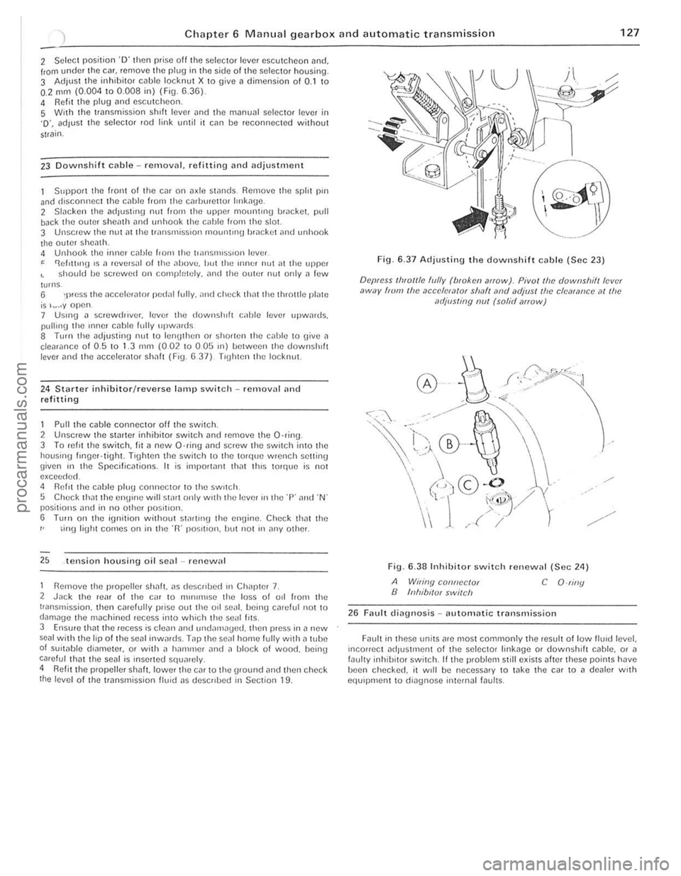
6.37 Adjusting the downshift cable (Sec 23)
Depress Ihlollle hJlly (bloken arIOw). Pivol/he downshilllev,·( ,)wuy frum Ihe ,1ccelef,1{Qr sllMI lind UdjllS! Ih e clcarance at Ihe MljllSling nul (solid arrow)
~r:;0/,/5.;~··ll ~
Fig. 6,38 Inhibito r switc h renewal (Sec 24)
A Wiling connector B Inhibl/Ul swilch C O-riny
26 Fault dingl10sis -nutornatic Ir
"."
" , .
, ,
J
,
procarmanuals.com
Page 135 of 205
1
134 Chapte r 8 Rea r axl e
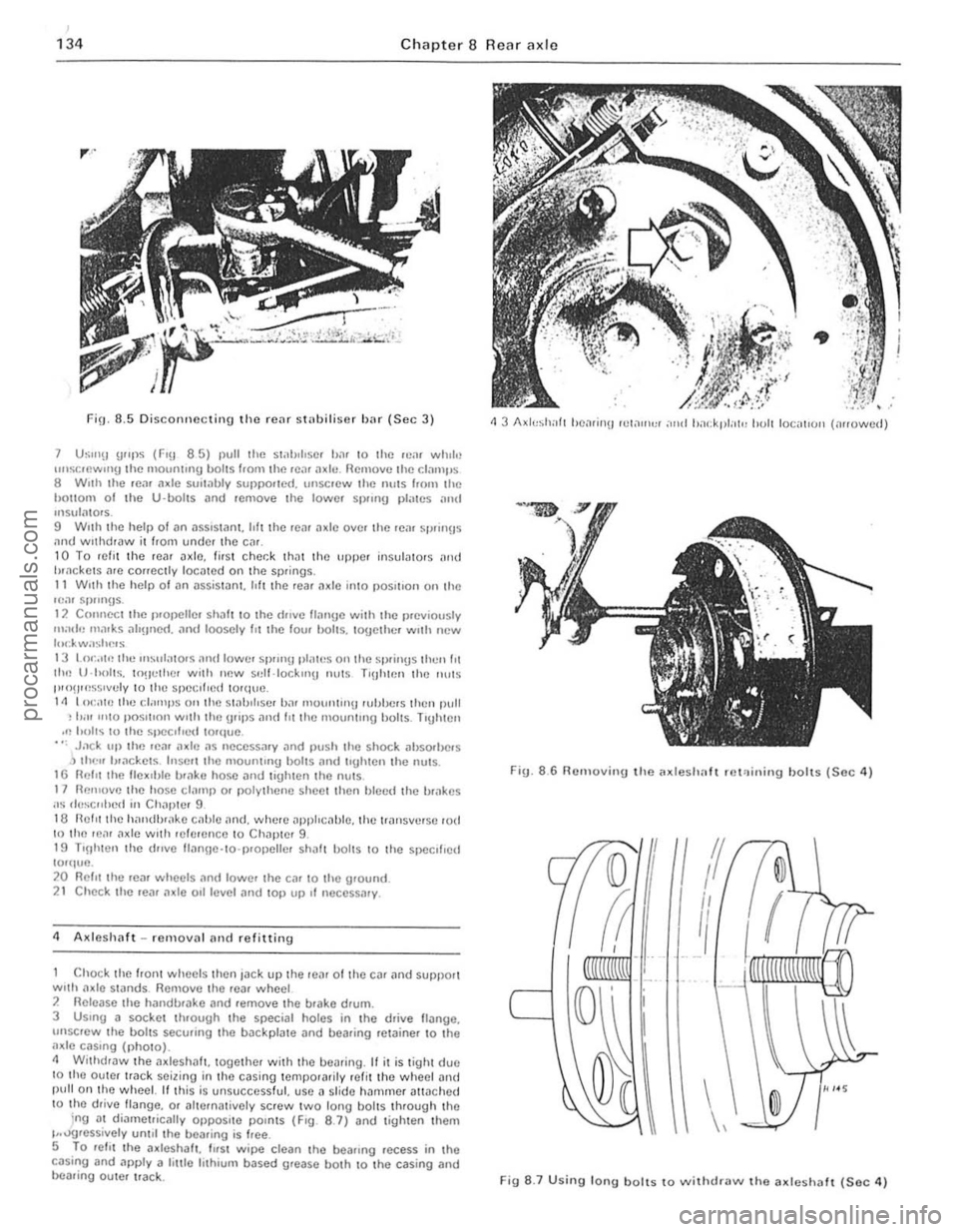
FiO. 8.5 Discorlllccti!l9 the rcar sI"biliser Iwr (Sec 3)
7 U~"'!I u"ps (FlU 8 5) I)UU rile s1.1h,l,s(lI b.ll 10 lilt:! lCol. while unstocwIIlIJ the mOlllllnlU I)oIIS from the Ie;)' ;l~II!. flcl110vc the C!JIllI'S 8 W,lh the rC:II Ildc sUlt,lbly SUIlI>o.ICd. lIIlSCICW rhe nulS hom the hallom 01 the U-bolts i1rld reOlOlle rhe lowel S I)llrlU p l;lrcs .. ",t! 1115 .. 1<11015. 9 Wllh rhe help of an asslSlilnt. hft the rem a~lc over the "~
Chock Ihe front wheels then jack up the re,lr of the c~r ilnd support with onle stilnds. Remove the .ear wheel 2 Ilelea se the hilndb.nke and .emove Ihe brake drum.
3 USIng a socket through the special holes in the drive lI.::tnge. unsc'ew the bollS secu.ing the b.::tckp late and bearing ,el.::tinor to tho a~le cilSln g (pholo). 11 Withdraw tho a~leshnft. together with the bearing. " it is tight due 10 tho oulor Ir
ig. 8
.6 RelHoving t h o Mdeshalt .e l'l ining hoits (Soc 4)
If
I
/1
II
I
\,
Fig 8 .7 U sing long bolls to ""ithdra"" tho a~leshaft (Sec 4)
cd
procarmanuals.com
Page 144 of 205
) Chapter 9 Braking syste m 143
2
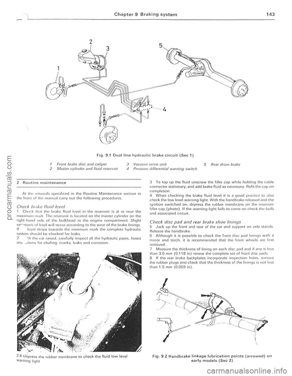
Fig. 9.1 DU
2 ROlltine maintenance
Al III<, u,h!lvals speClficed in the Routine M
2.4 ;-.-
uejJ.es~ the rubue' membrJne to check the fluid low level
Warning IrUht
3 To top up the fluid unscrew the fill er cap whrle holding the c,lhle connector sWtionar y. and add brake lIuid ns necessJr y. R efit the cnp on completion. 4 When checking the brnk e fluid level it is n good practice to also check the low level wnrning light With the hnndbwke rele
Re leuse the hilndb'
Fig. 9.2 Handbr a ke lin k ag e lubrication points (arro\Ncd) on early models (Sec 2)
I .
i
! j..
1:
, ,
procarmanuals.com
Page 146 of 205
) Chapter 9 Braking system 145
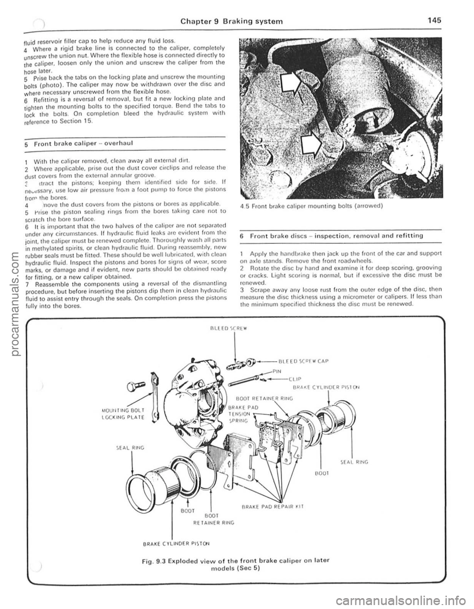
/ll.Iid reservoir tille , cap \0 help roduce any fluid loss. 4 Where a rigi d brake line is connec ted \0 the calipe r, comple tely unscrOw the union nUl . Where Iho flex ible hose is connected directly \0 Ihe caliper. loosen only .he union (lnd unscrew Ihc caliper f.om Ihe
hose later. S Prise back the laus on the locking plale and unscrew Ihe mouming boilS (photo). The cJliper may now be wit hdrawn ove r th o disc and where neCessary unscrew ed from Ihc flex ible hose, 6 Refilling is a revCfsal of fernOv;!I, but lit a new locking plate and
l ighten the mouming bol ts \0 the specified torque. Bend the Inbs \0 Io<:k I he boils. On comple tion bleed the hydwulic system wit h
reference \ 0 Sec tion 15.
5 Front brake caliper -ovorlulU l
1 With the c~liper removed . cle~n away all external dlr1. 2 Where applicable, prise out the dust cover cirClips
IrOIl' lho bores. 4 nove tho dust covers Irom the pistons or bores as apphc
45 Front brake caliper mounting bolts (arrowed)
6 Front brake discs -in spection. re rnovnl and refitting
Apply the hilndlxake then jn ck up the hom of the car and support on :1xle st:1flds. Remove the Iront roadwheels . 2 Rotate the disc by hand and examine il lor deep scoring, grooving or cf1lcks. light scoring is normal, but if excessive the disc must be
renewed.
3 SCrJpe
--
1-""£0""""" ~Plf'l ~-____ ttIP
BI"'~( ".",~"" PI~I()'
4IOUf llltlGOOLI tCCKltlG PLATE
R( 1 Altl{R RltlG
BRAKE (VLIHOER PISTO'l
(l001
Fig. 9.3 EKp loded view of the front brake calipe( on fater models (Sec 5)
RING
., .,
,
procarmanuals.com