light FORD CAPRI 1974 Owner's Manual
[x] Cancel search | Manufacturer: FORD, Model Year: 1974, Model line: CAPRI, Model: FORD CAPRI 1974Pages: 205, PDF Size: 43.75 MB
Page 168 of 205
) Chapter 10 Susp e nsion an d steerin g 167
• ____ I,,, .. r,,,.,
.. , ..
"""""
/
..... . '''M'
""'''''' . ..... >'< '.' AU ... , ..... • Ut ~" ... '''toI •• " .. (', @
........ ' ........ -~~ ' • • ~Mr
.,,·,"'·'·,v"""" ".$"'" ''''.''''.",,~. ~
."', ~
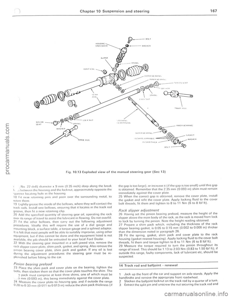
F ig. 10. 13 Ellplodcd view o f the IlHII HHl I steering gear (Soc 13)
No 7.7. d"lI) ''''''''':1\:1 )( !) nit" (035 Inch) deep
22 Wllh the ~Ieelmg Ueilr mountud III iI so h·Jawcd yice. remoye the r,:u:k ~I'ppur coy", pl!!Ie. shim p,1ck. {lilskor. mid sprIng . Also "Jmoye the I"n'on bOilflll\J coyer plalC. sh im pac k and gaskot. It i1ny oil is lost dUIIIl!) thc adJustfllenl procedures thO steering gea r must be rl!'
plc'''~hcd hclore IllIIng to Iho cm.
P,niOIl bec1ring preload 23 PlilCC the shun p,l c k alld covcr pl1lle 011 Ihe bearinU. lighten the 'JOlts. then s lacken Ihcm 50 .hal Ihe covel platc louches the shim The \' pilck Illll~t (;omj}lIs e ill hlil st three sh ims. one 01 which musl bc Q m,n (0 093 In). tlus bern!) ullllledlalely agaIns t the COYcr plate. 24 Measure Ihl! COV'" pl,lle .to·housllIg gilp. and if outside I he ranUe 02810033 fllill (0 all 10 a 013 In) reduce 'he shim pack th ic kness {If
Ihe UilP is '00 li1rud. or Illcrei lse II ("the gap IS 100 slllilll) unlll Ihls gill) IS Ob'ilillcd Remembe r Ihat lhc 2 35 111m (0 093 III) shim Illustrcmillll
Immcdiately "UilIllSt Ihe cover pl;)'e 25 When the COIICCt \1.11) IS ohl!!lIlcd. rernoye Ihc coy!;'. pl"le. IlIs!.111 thc gasket ilild r efit ,ho coyer ,)IJ tc. Am)ly locklllg lIuid 10 Ihe coyer hOi' th.eilds. lit Ihem ;)"d lighlen,o a 10 11 N m (6 \0 albf It).
Rack sl/iJpcr .1djus(mell( 26 HilYlllg set thO pOlllon bearing preloJd. measure 'he heIght 01 the stopper il!J.OYC the IIIillll body 0 1 the rJck. as ,he rilck is moyed Irom lock \0 lock by turnIng 'he pillion NOIe thc height reilding obtained. 27 Pr CPilre ;l shim pack w hiCh. Including the thickness 01 the 'ilck sloppe r beJring {JilslIet. is 0.05 to 0 15 mill (0.002 10 0 .006 in) thicker than ,he dimcnSlo n lIoted In piuagrilph 26. 2a FII Ihe spring. gas ke t. shim pilck and coyel plate to 'h e ra ck housing (gaske l ncareSt housing) Apply locking lIuid 10 the coyer bolt thrcads. III them illld 10rque tigh.e n to 8 10 11 Nm (6 to 8 Ibl h). 29 Measur e thc ,orque rC(tullcd \0 lurn Ihe p inion throughout i,s mnge of I!.lY cl. ThiS should bc 1 t 3 10 2.03 Nm (0.83 to 1.50 Ibl It); if oulside th,s ,ange. Iilul,y componcnts. lack ollubriCilnt etc. should be
suspected.
1 4
Track rocl end balljo int -renew al
Jack up thc loon. Of thO Cil r and SUf)pOrt on Jx le stands Apply the halldbrilke ;)nd re!llove Ihe applopriil'C Iiont roadwhcel. 2 Slacken Ihe baliJo in l locknut 011 the track rod by iI quarter 01 a turn. 3 Extra ct the spl, t p,n Jnd unscrew thc nul securrng the !Jilc k .od ond
, .. • • ..
::
procarmanuals.com
Page 169 of 205
)8 Ch apter 10 Suspensio n and steering
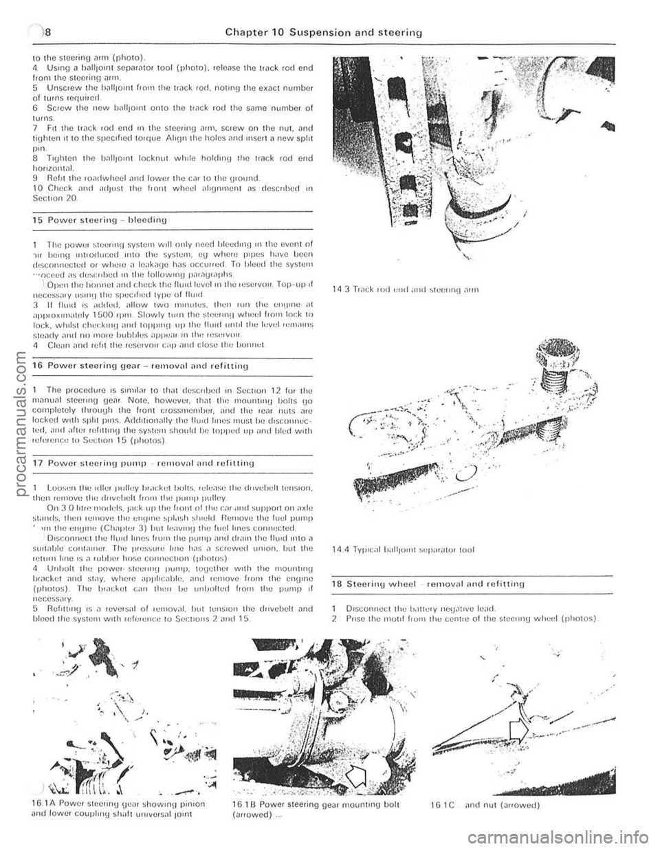
\0 the SI(lcring Mill (photo) 4 USlIlg" 1)[lIi)onH SCpilriltor tool (photo). reh:o,lS(l the ['ilek rod end from the Slc(!rino ""m 5 Unscrew the h,"'IOlilt hom the ['
The power ~1P.elln\J SysHllll WIll only need blc",rhnfj Ifl the even! of . .., hell1\J Il1tl<)(hu:ed ",to the system. cu whcn: IH llI:S h;IV() IW(}1l dlscoI1l1cc«:d or whel() J Ifl.lk"(Je has occlUfed To hleed the system ···ocp.ed ;'s (1<,~<:"I)Cd III 1(11) followlllU l),l';)\J,,1I)hs
I Open llH~ hO'Hl()1 ,111<1 cl\p.(:k the Il",d h:v el "llhe Il'Sl'IVi'" Top·llp.t llucess;IIY IIS"'!J (Il<) spe.:II,ed lype of 11(11<1 3 11 11."d IS added. allow two "'''HlWS. th"l1 lUll 11m I;I\U"W at apPI{)xIIllntnly 1500 rp'" Slowly \illll lhe st'!""Il(! wheel 1,0m lo,:k to lock. wlllisl r:l\.,,;klllH and WPP"'!I up Ih e Ihlld unlll th" l"v,,1 ",m;II11S
Stf),li1y ;1<\<1 no molC hubhl"s ilPP":U I II tlw I"S,,,V,,II
" elc ;,", and refn Ihe r"servoll cap ami close II,,, 1>0"",,1
16 Power steering gear rellloval and refittinu
The p'ocedure IS Sllml", to thilt descrd)<)d III Sc(:t lon 12 10' th" m,10u,,1 steeling gC,lf NOlO. how"ver. lhm tile 111011111(1)(1 1)I)Its (jo cOllipletely tl1(ouyh lhe front e,ossmflmhe,. "nd the II.),,, nil IS a,e
I()(;ked wllh sphl pillS. Add,llon"lly lhe lIuld IIIH)S rnu~;t Iw lhsc.onnec · l"d. and atln' ,uI,Um!J the system ~hollid he loppud III' ,lnd Illed wllh lui"",,,!:,, 10 $"(;tl{>n 15 (photos)
17 Power steerillU pump remov;ll "lid rcfil1 ill\J
Loo~"n tl", «II.." Iwlley 1",lck,,1 b"lts. ,el..,ase Ih" d"ve!Jclt lellSlon. Ihcn ,emOVe II", dllvelu:lt I,,)m the P"'''I' pulley Oil 3 0 101", IIIO
h,;lc.k(,t ~nd st;)y. wlw,e ;1j)1'11 <:;,I)I". ,!Ill! ","'ove f'DIII Ihe CII!) "le (photos). The "",d..,1 C;'rl lh"" 1m (lnl)nlt"d flOm Ihe pUlllp of nccess;"y, 5 RellltlllU IS .1 ,ev,,'~al 01 I..,moval. "ul l"'Il~lon Ihe lhlvehelt ~Ild "Iced Ihe sy~IC'" wllh lek'e'll:tJ to Sec;1I0ns 2 ,!Ild 15
"V',~, , .,' , -t .~/ ,.
~
' ---... . . ' .. ' , "
A-i·J<'~ r~ _ I' .' If! h \l:: fITI \~, . '''''
~
•• :. ' 10)",', / )
. .. 'I.· L../,
'": .. ':;' ., .... ---,.
. .. .
18 S teerinU wheel removnl nnd rIllittinu
1 Dlsconneci the lodlielY nCU~lIve le,,(1, 2 PIISC Ih" mOllf hUIll Ihe celn,,) o f Ihe stcclln(j whc,,1 (photos)
15.1 A Powef SICCIIIl(j (je,, ' showUlU pinlOrl and lowe, coupl",U ~h,,11 un,vcfsnl lo;nl 161 B Power steering ue", mountUlg bolt (,,"owed) 1 G 1 C "nd nul (""owed)
.' ---------------------------------procarmanuals.com
Page 172 of 205
Chapter 10 Suspension and steering 171
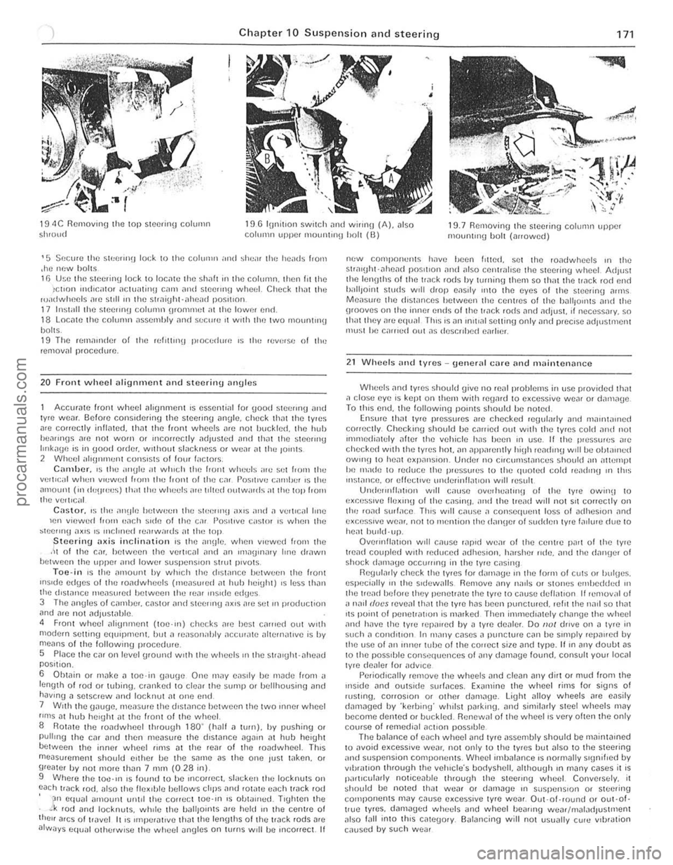
19 4C Removinu the top steering column Shroud 19 G lunitlon SWitch ,1nd wirlllU (A). also COllll'lII upper mOlUllnl!J holt (0) 19.7 Removing the steering column uppcr mounlul(J holt (arrowed)
'5 Secure Ihe SIt:(;(1I1(1 lock 10 Ihe colulIlIl ,lIal ~heil' the h eads I,om ,he m:w holt~ 11) U~e the stecrin\J lock to locate the shaft in Ihe column. then III Ihe )ct,on mdlGltor OICIlJalinn GUll alld Stecrmn wheel. CtlCC~ that Ihe ruadwheels afC st,lIln the 5trai\jht·ahead P05,110l1. 17 Install the Stce!Ul(J column orommet Oil the lowm en(t. 18 LOCille the column assembly ami sr:c",e It wrth the Iwo mOllrlllng bolts. 19 The ((,milliuler of the rellllUI\J proccrl",e ,~ th" reverSI! of lhe removill procedure,
20 F ront wheel alignment and steering ilngles
Accurate front whcel alignment IS essential lor good stoer"'g and lyre WOiJr. Scion) cons,dering the steering angle. check Ihat Ihe tyres
are correctly inflated. tllnt the front wheel s arc nOI IJlJckled. the hub hea"nns arc not worn o r mcorrectly adjusted und thilt the sleflr"'g IlIlkaUfl is in IJood order. wllhout slackness or we,ll at thu Jo,nls
2 WIH;f; 1 "I'!JIununt co"s'st~ 01 loUl I"ctors, C;"lliJcr_ IS the ""Ule "t wilich the front whet:ls ,lie sci from Ihe
verllcal when v'ewud 100'" the IrOnt 01 the c"r 1'0sIt,ve camber 's Ihe .. mount (111 de\J'ee~) th"t til() whucls ,ue toited outwards at the lOp 100'"
thu vert,c;,1
Castor. ,~tho i"'~Jlu between the SIl,erlIlU ,,~,s OIrld.1 v..,'I,e.11 lone len viewud IrOIll p,lch ~,dfl 01 the C,lI 1'0~;llIve castor 's when the ~tcermu ",x,s 'S ",cloned rUiHw,,,ds ill the top jStcerinu ilxis inclin,,{ion 's lhe illl\Jle. when VIewed frOI11 the .It 01 the Cilr. bel ween the verltcal and "n 1Il'''U>I1.1ry hne drawn betwCl)n the upper ilnd lower suspensIon strut p,vots, Toe-i n IS the ilmoUl,t by wh,ch tlte dl5li"'Ce helween the frOrlt
IIlsuJu ed\Je~ 01 the rOildwhecls ('He,lsu1ed m huh heiuht) ,s less thiln lhe d'sWrlCI) ",e
6
Oht"in or m"ke
ne:w components have heen I'lted. set the ro"dwheels ,n the stral\jht·ilheil(f p05otrOn and also cent",lrse the steering wheel. AdJ"st the len\Jths of the track rods hy lllll1ing tltem so th,,! the track rod end IJ,litJoinl studs w,11 drop eils,ly onlO the eyes of the steer inu ilrlllS Measllfe the dislilllces between the centres of the hilllfOllllS illld the grooves on Ihe inner ends of the track rods and ildjust. ,r neceSSilry. so Ihiltthey me equ,ll Thl~ is all lII,t,,,1 sellinlJ only and prec,se ildillstmellt mu~t he carried oul as descrrhed earheL
21 Wheels and lyres -uonNal care and milintenl1nce
Wheels ilild tyre~ shOuld give no reill problems in usc provided thm ,1 close eye IS kept on Ihe", with re\janlto excessive weilr or dilmilge To llns end. the following pOllltS should he noted Ensure thm lyre pressures ",e checked re\Jularly ami ma,ntallled correctly. Checklllg should be c,Hried out woth the tyres cold alld nOI IIlHlledialely alter the vehicle hilS heen "I usc. II the pressures are checked w'th the tyres hOI. iln ap(l,Hently hi\jh readmlJ w,1l be ohw'lled OWlnH to heilt expJnsron. Under n<) Cllcumst
eSpecii\lIy 111 the s,dewalls Remove any na,ls or stones ell\bedded 111 the tread hefore they penetr"te lhe tyre 10 cnuse dcfliltlon If remov,,1 {)i
dilll1i1ged by ·kerbing· wh,lst par king. and simililrly stee l wheels may hecome denIed or buckled, Renewnl of the wheel rs very ohenthe only course of rellled'ill ilct,on poss,ble, The balance 01 each wheel Jnd tyre ilssembly should be mainta,ned to ilvoid excess,ve weilr, not only 10 the tyres but illso to the s teering and suspension components. Wheel imbillilnce 's normilily S'\ln, f,ed by v,i)rilllOn through the veillcle·s bodyshell. illthouUh III many c~ses it IS piullcularly nOliceahle Ihrouoh the steenng whuel. Conversely. it ~hould bc noted thilt weilr o r dilnlaUc 111 suspellS IOll or steer ing components may '.:ause e~ceSSlve tyre wear. Out·of·round or out-of· t!Ue lyres, damaged wheels and wheel !leafing weilf/ nlilladJustntent also lilll into th
,.
:.
procarmanuals.com
Page 177 of 205
)76 Chapter 11 Bodywork and fitting
General description
The body is of all-s teel welded construction with impact ilbsorbing hont Dnd rear sections . Anli-burSllocks nrc lilted 10 the doors, ilnd the
t ailgDte is supponcd by \J
AI the in1erVills speCIfIed in the Routine M"IIl\cnilnCe section in the front 0 1 the nl
Check underbody protective coatiog 5 W,th the CM supponed on i1xle stilnds. check the cond,tlon 01 the un(lelbody protcctivc coating. i1nd wherc neceSSilry clean
M,,;ntcll
Wily to remove any aCCUIllUI,lted mud whIch WIll retillll mOlslu re
Mats and C
very line culling pils te. Finally, opply wax polish. WhNe the scrotch has penctrDt(ld right through to the metill of the bodywork. causing the mowl \0 rust. iI d ifferent repa ir lechnique is
required. Remove any loosc rus t fronl the bottom 01 the scra tch with a penknile. then apply rUSI inhibiting paint 10 prevent the lormation 01 rust in Ihe future. Using n rubber or nylon appliCiltor fill the scratch with bodystopper paste. II requ ired. this paste Ciln be mixed with cellulose thinners to provide a very thin paste which is ideal for filling narrow scratches. Before t he stopper·paSI(l in the scratch hardens. wrilp il piece 01 smooth COllon rJg i1round the lOp 01 J linger. Dip the finger in cellulose thinners and then quickly sweep it i1CIOSS the surlace of the 5topper-pJste in the scratCh: this will ensure tha t the surfilce 01 the stopper,pilste is slightly hollowed. The scratch can now be p
first wsk is to pull the dent out, untrl t he affected bodywork almost
procarmanuals.com
Page 178 of 205
) Chapter 11 Bodywork and fittin g 17 7
~!t~InS its oriOin,11 sh~flC. There is lillie point in trying to restore the original s hllpe complClC ly, as the me1011 on the darnllged arca will have stretched on impact ilnd cannOl be reshaped fully !O its original contou r, II is belter to bring the level of the dellt up to 11 poin t which is aboul ~ in (3 111111) below the level 01 the surrounding bodywork . In cases whe.e the dent is very shallow anywi'lY. i, is nOI worth trying \0 pull 1 ou t 111 all, II the ull{lersidc 01 the dent is accessible. il can be hammercd oul gently from behind, using a malleI with a wooden or plastic head. WhilSt doing Ihis. hold a suitable block of wood l'flllly a{),111151 the outside 01 the panel 10 absorb the impact from the hammer blowS and thuS Il,event 11 Imge area of the bodywo.k hom being 'belled,ouf, Should tho dem be in a section of tho bodywo.k which has iI double skin or SOI1IIl other filclOr mokil1g It inaccesslhle from behind, a
dllferent technique is cillied lor, Drill severill sm;1U holes through the
mewl II1slde the i1reil (Jilrtlcul,ldy in tho deeper section, Then screw long sel1·tap~ing screws into the holes IllSt suffIcien tly for Ihem to gilln iI good purchase In the mewl. Now the Ilen t C"n he 1)lJlled out by pulllllg on the protruding headS of the screws wllh iI pnll of pliers. The no.t stilgo of the rep,lir is the .emOllill of the PilUlt from the 113Ued meil, and hom nn Inch or so of tho SurroundlilU 'SOUfl(r
Jdywork , Tills is accomplished most oilslly by usil1U a wire brush or ab'~sllle pild on " ,)owe< dflll, ~,lthou9h It Clln he done Just i1S e ively hy hnmf usmg shoots 01 1I1)'i151110 P.l,)C •. To COlll,llete the p
thorelore decide whether to renew the whole polllel (II this IS possihle) or to .ep[lir the affoctod illoa. New body Po1nols arc not ,1S expensive as mos t flCOple think and it is often (Iuicker and mo.e satislacto • .,. to fit" new t)anelthan to auempt to rellair larue n.e,1S 01 corrosion.
RenlOlifl all f,llln\Js hom the .. lIeeted a.o" cxcoptthose which Will
act ~s ,1 uu,(ie t o the oliUllwl shape 01 the (i,lIlla\je(i bodywork (ell hn,1(1lnll1l) ~h.~lIs etc). ThOll, USlnu tin snIps or ~ h"cks
d epreSSion fo r Ih c frllcr pas\(!
'll/lle hrush the aHected Me[l to 'CIilOlle tiro powdery rust from the ,ICO 01 the lelllilllllll!l lIlet,,1 P;lInl thc "flected arc" wllh lUst
IIII"I)ltll1l) p""'t. If the hilck 01 the ,usle.1 me,1 's accesSlhle treolt tillS
" delo.o frlhflU cml t
me sh. or altlflll1l1um t",Joe. AlulIll"'um 0' pl;1strc mesh IS Il.oh"bl.,. lile hest m
Aluminium wpe should be us ed lor slll ;rll 0' vCly narrow holes. Pull a picce oil tho .011 ond tri'" It to tho apIl
ove . the hole, rt C[ln be overlapped II tho thickness of one piece is
i nsufficient. Burnish down the 00ges of tho tapO With the handle 01 "
screwdrillC ' or srmllOf, to ensure that the ",po.s securely auached to the
metal undomeath .
Bodywork rCIJ<1irs -filling a"d re-sprayi"g BefOte uSlIlg thiS Seetion, soe the Sections on denl. doep scratc h.
rust holes "nd gash repai.s . M~ny types of hodyfllfer Me ~val'ahlo, but Uonerally spe~k.ng those nrOpnelOry kits which conlain 0 till of f illor paste and a tube of resin h~fdener Me best for this type of rcp,llf A wide, !ieKilJle pl
hardener carefully (follow the m"kCI's instructions on the pack) othe.wrse thO folic. Will !>tt too rill)luly or tOO Slowly . Using the
"pplicator apply the filler paste to Ihe prcpared area: draw the
applicalOr across the surfaco 01 tho IllIer to achieve the correct contour and to lovel the fillef surface. As soon /1S it contour that approxim"tes 10 thO corrOCt one is achielled, SlOp wo.kinU the pas le - il you carryon too long the pasto will becomc sticky and begin to 'pick up' on tho
app lic"tol. Continue to add thin layels of Iiller paste at twenty· minute intervals until the level of the filler is just pfoud of the surrounding bodywork Once the IllIer has hardened, excess can be removed using a met;!1 plane or IiIe. F.om then on. progressively finer grades of abrasive paper should be used. starling with a 40 grade p.oduction paper and l.nishing With 400 o."de wet·and·dry paper . Always wrap the abrasille p"pcr IIrOUlld a flat rubber, cork. or wooden block -otherwise the surfaco 01 the frller Will nOI be completely flat. DUling the smoothing of the fIller SUI face the wel·and·dry paper shoufd be periodically rinsod in walCr. ThiS will ensure thaI alle.y smooth linish is imparted 10 the frller (It th O flllni SHIIJO. At t!\l S st1lge the 'dont ' shoul(! be surrounded by a ring of bme
mowl, whIch in IUfn Should he encirclod !.Iy the finely 'feathered' edge
0 1 th e good paintwork . Rinse tho repair nrea wilh clean water, until all 01 the dust I>roduced by the rubblllu·down operation has gone. Sp."y the whole .ep.1ir a.oa with" light coat of primer -this will show UI> any ,mpcrfOChons in lhe su.face of the fll1e •. Repai. theso Iml)CdectlOIlS with frosh 1,110' paste or bodySlOpper, and onco mOte
smoOth the sUfl
he call1od out in a w".m, dry, wind loss and dus t free atmosphero. This condition can be created mtllicially II you have access to a large indoor working "reil. but rl you nre lorced to work in the open. you Will have to pick your day lIe.y ca.efully . II you a.e working indoors. dousin\J the
floor in the work mea with water will holp 10 SOllie the dust which would otherwise be in the iltmosphe.e . If the ,epai. mea is con fined to one bod.,. pilllOl, mask off tho SUffoundlflg panels; lhis Will hell) 10 minllllise tho effocts 01 a slight mis,match in lH,lint colou.s Bodywo.k hUUlUS (eU ch.omo strips. door handles Otc) Will "'SO noed to be
"';1sked ot! Use uenume fII
S ilray on t he t op CO"1. "\Jain bUlldmu ull the tluckness by usul9
sOllof1lllhlfl'"ye .s 01 p<111l!. S Ia .t spraying in theCllnlre 01 the .epair mOil and theil, USH\g a clfcular mOllon, work outwards untrlthe whole ropmr
"rea ond al>out 2 inches 01 tho surrounding origmal pallltwork IS COvered Remolle allm"sklng mnteflaf 1010 15 minutes alter spr
Plastic compOllc"ts Wllh the use 01 mo.o and more pl"stic l>ody components by the
vehrcle manufac turers (eg bumpers, spolle.s. and in some cases major
body panels). reCllilcation 01 damago to such items .hilS .t.>e<:0me a
mOller o f eHhor emruSling relhl'r wOtk to a specialist m thiS field, o. renewing complete components Rep"ir by the DIY owner is nOlleillly feaSible owing to Ihe cost of the equipmen t and materials reQui.ed for effecting such repairs. The baSIC technique inllolves making a grOOllo
atong th o hno of the crack in the plastic using a rotary hurr in a pow~r drill. The damnged pal! is then welded hack togeth er by uSing a hot "" gun to heat up nnd luse a pl
polyca.bonate. ABS, poIYllropylene) .
procarmanuals.com
Page 190 of 205
-
) Chapter 11 Bodywork and fitting 189
/~
32 8A I',,~c 0111 Ihe alp 32 an ali(I ,(,mo .. c the console screw 329 Removing the hnndbrake lever boot find be~el
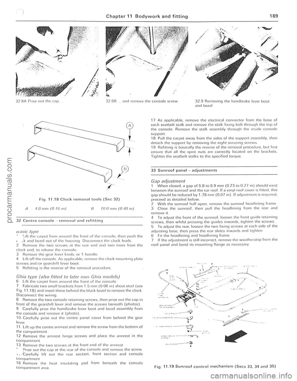
Fig.n.la C lock ro:.,,"ov
32 Centre cOIl~ole·· fUIllUV,,1 ,,,,d refiUinu
IJasic tYlle '.111 Ihe caqll:l 110m ;!lolllni the r'OIlI of t im t:()Il~()lo, thun push the " .J
33 Sunroof piln el -ndjustments
Gap adjustment 1 When closed. a Unp of 5 8 10 6.9 mm (0.2310 027 "') should eXI~t hetwecn thc slIn(oof and (h e CM rool. II;) vmyl roof cover IS lilted. Ih,s gap should he reduced by 1 .78 mm (0.07 Ill). If adlllst'!\(Jnl IS requued. pwceed ns detaIled below. 2 With the sunrool hall open. remove (he sunrool heildhlunll hnlne 3 Close the sUllfool. then pull Ihe hei!dhnll1H hOIll (he Ie." and remove ,I. 1 To ndlust the hOnl 01 the sumoo!. loosen the front Uu,de relillnu1U screws. then whIlst p,essu1!J (he Uuitles IIlwilrds. lighten thc screws. 5 To ;)d,ustthe rear. loosen (he twa h.II1!) screws nt eneh Side of the ,1dlustinU hnsc. thcn p,ess (he reilr shdes mw,uds ,1"d t'Uh!Cn . 6 F,t the hCildllmn(J and hemU",,,,U h,,,ne 7 lithe ild)lIsunenl is slill Incorrect. ,emove (he we,l\hel$I"p from Ille rool panel ;)11(1 hend ,IS mountll1g lIange as necessary
.,.,.'~ ..... ,,--...... ;;
• · .. ···"'·' -·0 . .'--
,"·""",-- 'r
FiU 11.19 Sunroof controllllechanism (Secs 33. 34 and 35)
, . , , , ,
I
,j
procarmanuals.com
Page 194 of 205
Chapter 11 B odywork an d fitting 1 93
)~--------------------------~-- ------------
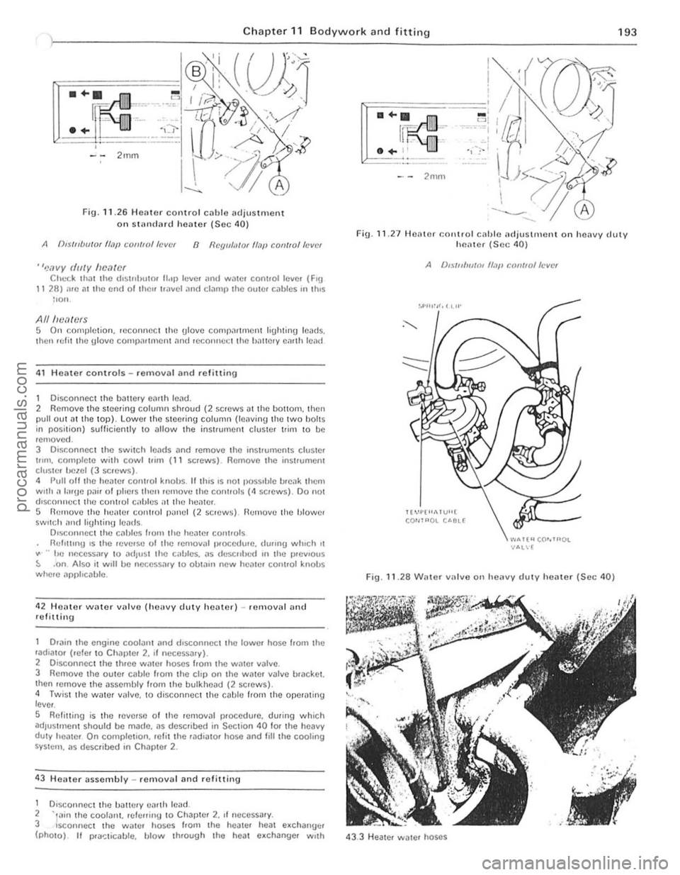
Fig . 11 .2 6 Heilter control cil blc 1Hljus tm ent
on SlHn (IMd heilter (S ec 40)
A (),.\·/"UlI/Ot flajl COII/ro//aVllr 8 I/Cgll/;I/O( Il.7p con/fo/h'vt'f
"'!ovy dilly IIfHltOf Chl.-r.k thilt Ihe d'Slflhutor 1I"p levc. ,HId WilIC, cont.ollcve. (FlU 11 28) we 011 Ihc cnd ollhl)" Ir,"vel ilnd clamp Ihe oulC, cablcs "I \IllS lIon.
AlllwMCfS 5 On complct ion. reconrWC I Ihe ulove comp;lr llllent liUhtinU leads.
Ihen lelil Ihe Ulove COllll)nltrllell1 nnd reconnet;1 Ihe hnllelY emlh len {1
41 H OMe r controls - removal and refittinu
1 Disconnect Ihe ballery eimh lend. 2 Rcmove Ihe s teer ing column shroud (2 screws D tthe bOliO",. then pull oul .lIlhe lOp). Lo wer thc stee.ing column (lel\Ving Ihe twO bOltS in position) sufficiently to ullow t he inst.umenl cluster I rim to be remOve d. 3 DIsconnect Ihc switch 10MIs ;lnd remove the instruments cluSIO' t"m. COllll)lot e with cowl "im (11 screws). Rcmovc the instrumont clusle r l!clOI (3 scrcws). 4 Pull oil Ihe hOiltor control knobs. II t his IS 1I0t possIble I>
.. hc neccssmy 10 adjust th e callies. as dl.'SCfllled III the p.evlous ::. .on Also it w,1I be necessary to obtall1 new hCille. control knobs where npphcable.
42 HCHte r
water villve (hellvy duty heater) -IC lll oval an( 1
refittin g
Drilin
the engine coolant ilnd dlsconncct tho lowe. hosc !rom th c ,aulato. (,efe. to Chapter 2. II necessary). 2 Disconnect Ihe th.ee water hoses f,olll tho Wille. valve. 3 Removo the OUWr cilble from the clip on the WilWr v~lve bracket.
Ihen lenlOve the assembly from the bulkhead (2 screws). 4 Twis t the wate r valve. to disconnect the cable IrOI11 the operilt ing
l ever .
S Relilling is Ihe reve'so of the removal p.occdure. during which ~dJustl\lcnt should be m~do. as described in Section 40 fOf the heavy duty healCf On completion. re li t the rudiutor hose and fililhe cooling SYSt(:rll . us described in Chapler 2 .
43 Heater assembly -re mova l and re fillin u
1 DlsconnOCl lhc tJiltH:ry ea.th ICild. 2 -,,,in the COOIIlI1l. rei!;fliny 10 Chllpte. 2. II neCCSSilry. 3 sconnect th e Wiltcr hoscs from the hoale. he;!t e.chanuc. (phOtO). II I>
- ' = 1 --·-~··""I c,
'1,:-1
F ig .
11 .27 Heale r COl\trol cilhle ncJju stm ont on heilvy cJllty hl"latot (Sec 40)
A /),., ·{n/w/III If,}!, CQII/lo/ft'vct
Il"'·I·"1>.1 VU[ CO""'OL U·OL(
".."Tt"CO""'OL -NIL\[
Fig. 11.28 Willer varv e o n heavy duty heilter (Sec 40)
43.3 H eiltel water hoses
i , , . ,,
"
procarmanuals.com
Page 199 of 205
)
Index
A
Accelerator cilble removal ilnd refining -14 shnft ilnd pedal removal and refining -75 Air cleaner removill Jnd ref,nrng cal buren or mod cis -68 fuel injecllon models -80
P rnator .,rushes inspecllon. removal and refilling Bosch -202 Femsa -203 Lucas - 202
dismantling and rcassembly -203
removal and refining -201 Antifreeze mixture -60 Automatic transmission descrip tion -122
B
downshift cable removal. refi11ing and adjustment -121 extension housing oil seal renewal -121 faull diagnosis -127
maintenance. routine -123
removal and refOlting -123
selector mechanism ildjustment - 126 rcmovill. overhaul ilnd refl11lng -125 speclflf:iltions -103 SI.1r1er IIlh'bilm/reVerse lamp switch remov
demister
noules reOlov
doms-178.180. 18210 185 face level vents removal and refItting -197 facia panel -188 fuel filler flap -188 heater -192 to 194. 196 10
uphOISlCry
and carpets -176 mirrors
-
192 open rem quarter glass assembly
removal and refitting -186
re~r qllMlcr trim panel removal and refitting -185 repi'lir millor damaue -178 minor damage -176 sent belts -191 seats -192 sunroof-189la 191 lailgate -180. 187. 188 torque wrench scuings -173 windscreen -180 Bodywork repair sequence (colour) -174, 175 Bonnet release c
Camshaft (3.0 litre engine) retitting -54 removal -50 Camshaft and camshaf t bearings examination and renovation 2 _8 litre engine -35
3 .0 litre engine -51 Camshah and front intermediate plate (2.8 litre engine) refilling -41 Capacities. general -6 Carburetlor (Weber) aulomat ic choke
adjustment -71 removal. overhaul and retitting -71
dismantling and reassembly -69 general -68 idling adjustment -73
procarmanuals.com
Page 200 of 205
)
rernoy .. ' and refl Uing -69 spcc,'iC
(IlIvchells
G3 e~p:mSloll I nnk 6<1 Ian hub l)()nllllH (30 hilI] 1110<1111,;) 64 f~ull (II;)Ul1osl~ 65
flll".U -
60 lIush"'9 59
",nmlen,lncc. roullllC 59
'ild,nlOr
GO speclficn llon5 57 lem,)er;!lurc unuuc Sf:n(Ie. unil -134 IhcrmOSl<11 -61 10Htlle wrench selll ngs 57 VISCOUS drlv\! 11'111 -63 W1)ler IWIllP 61 Crankca se ventiln tion system 2.8 tol'c engine -39 3.0 rillC engine 53 Cranksh1)ft 2.8 li l.e engine examinat ion nnd rcnoviuion -37 refilling -<10
3 .0 til.e cn gine examination lind renOV1'l110n -52 Crankshilft and main bearings (3.0 litr o engino) removal -51 Crankshllft pulley refitting (2.8 hIre engine) -44
removal ( 3 .0 litre engine) -50 Crankshaft r ear oil seal (3.0 litre engine) .efllling - 55 .emova l -51 Cylinder bores ~xaminalion and .enovation -36. 51 Indo r heads 2.8 titre engine dismanll ing .• cnova lion and .eassembl y -35
Index
D
refining - 45
3.0 litre engin e
. eassembly -55 refining -55 .emoval wilh engIne -49
removal wil h engine in car -49
Decarhonising -52 Dimensions. vehicle _ 6 Dim-dip lighting system _ 226 Disc br1lke s scc Front disc brakes Distributor overhaul 2.8 hlle engIne -93 3 a !r1l0 cng,ne -92 rcmoval and r efIlling _ 90 Doors eXle.io. hllndle ,emoval and refilling - 183 lock 1Issernbly removal and .efilling -184 pillar swi lc h -224
priVill e lock ,ernovill and ref'lIing -185 fnllics tracing nnd feCllik al ion -178 remOle conlroi hnndle removal and refilling -180 Hlmoval and rell\1l11g _ 185 Irim j>ilnel removal and ,efi ning _ 182 window Irnm c
moul(II ng nnd door wealhcrSlrips
removal and refining -185 rcmoval and relining -185 wmdow glass removal and retilling - 184 window regulnlor nssembly
r emoval and relilling -183 Drivebelt s .emov,,1 ilnd refil ling -63 Drum brakes sce Renl drum brakes
E
Eloc triclIl.system -198 e/ seq Electrical systcm altell11110, -201 10 203
ilu xiha.y driving "ghl -212 bmlery -200. 201 bulbs -199.21310217 ciga. IighlOf -225
clock -223
d escrip llon -200 dim-dip ligh ling syslem -226 laull diilgnOSIS -19. 233 ""sher unils and rel1lys -225
fuse s -199. 220
headligllls -211 10213 horn -220
inSI.ument clUSler -22 1 inSI.ument vollage .egula lor - 226 Inmp5 -21410217 mninlenance. fOUline w 200 mobite r"dio equIpment - 226
precautions - 200
rildio /casse tte player -226 specif ications - 198
speedomeler cab le -226 Slmte . mOlOr -207 swi tches -223 10 22 5 lailgall) wash er -217 laHgme wipef -217 to.que wrench sell ings -199
w indscree n washer -219 windscreen wiper -21810 220 wi.ing diagrams -235 10 249
25'
Ii
procarmanuals.com
Page 202 of 205
inlet manifold - 83
main system components remova l and refilling -80 m~intenilnce, routine -79
specificiltions -67 to rque wrench settings -67 Fuel pump carburettor system cleaning - 68 re moval and refilling - 68
testing -68
fuel inject ion system removal and refining -80 Fuel system (carbureUor) accelera tor cable -74
accelerator shah and pedal - 75 air cleaner - 68
carburetlor -66, 68 to 73
description -67 e~ haust manifold - 76 lault diagnosis -85 luel pump -68 fu el wnk -73, 74 fu el lan k fille r pipe -74 fuel tank sender unit -74 inle l manifold -75 mainte nance, routine -67 specifiCiltions -66 torque wrench senings - 67 Fue l tank cleaning and repai r -74
filler pipe removal and re fi\ling .-74 remova l and refilling -73
sender uni t removal and ref il\in g -74 Fuel tank sender unit (fuel injection models) -83 Fuses
G
general -220 specifica tio ns - 199
Gearbo~ see Manual gearbO K Gudgeon pins - 37. 52
pdbrake adjus tment -153 cable(s} and rod removal and refilling 155 lever removal and refitting -154
warnin g hght switc h -225 Headlights alignment - 212 assembl y: removal and refilling ~ 211 bulbs renewal-2 13 Heater assembly: diSI11(lntting and reassembly 8ehr - 19 4 Smiths standard and heavy duty -196 assembly: removal and ret.tting -193 contlols
adjustmen t -192 removal and refilling ~ 1 93 water valve (heavy dUly heater)
removal and re fitting - 193 History o f tho nlodal-5 Horn faul t tra cing . remova l and refilling -220 Hubs, front
bearings renewal -162 removal. ret lu in g and bearing adjustment -16 1 Iraulic systam (brakes) bleed ing - 152 pipes and hoses removal and refilling -151
Index
Ignition switch and lock -224 Ignition system -87 el seq Ignition sys tem amplrlier module (2 .8 l i\(e mode ls)
r emova l and refilling - 94
condenser (3. 0 litre models) -90 COntact bre aker points (3.0 litre models) - 89
description -88
dis tributo r -
90. 92. 93 fau lt diagnosis -96
firing order -87 mainteMnce. routine -88
spare plugs - 91. 95 speci fications -87
t im ing -94
torque wrench settings -87 In strument cluster ill umina tion switch -224 removal and refitting _ 221 Instrument voltage regulator removal and refilling -226 Interior lamp and bulb
removal and refilling -217
J
Jacking -7
L
lubricants and fluids recommended - 17 lubrication chart - 17 lubrication system
M
2.8 litre engine -39 3.0 litre engi ne -53
Main and big·eOld bO(lrings e~amination and renovation -37, 52 Main bearings (3.0 litro engine) removal - 51 Maintenanco , routine bodywork and fillings d oor ch ec k straps security check - 16 locks, door chec k Straps. tuellilte r C
h andbrake linkage lubricat ion -16, 144
h ydraulic fluid levul check /lap up - 16 . 143 hydraulic flu id renewal -16. 144
line s and hoses check -16
pads ilnd shoes we." check -16 , 14 3 servo check -16 . 144 vacuum hose check -16 Clutch adjustment chock -16, 98 cooling syslem
coolan l leve l chec k/top up -16, 59 coolant renewal -16, 59 drivebelt condl tion/wnsion check -16, 59 leaks check - 59 electrical system
ballery elec tro lyt e leve l cheek /top up - 16. 200 equ ipmen t opera tio n check -16. 200 headlamps cleaning -16
253
'i
'" , '.;.l
•
procarmanuals.com