boot FORD CAPRI 1974 Workshop Manual
[x] Cancel search | Manufacturer: FORD, Model Year: 1974, Model line: CAPRI, Model: FORD CAPRI 1974Pages: 205, PDF Size: 43.75 MB
Page 148 of 205

Chapter 9 Braking system 147
Br;'lke IlIlInU
Wheel Adjustment
"m
cylinder --·-·_.L
-::'~~:.J/
I
'j
~
l
~
• shoe hold down spring/pin
Br.lke shoe
Fig. 9
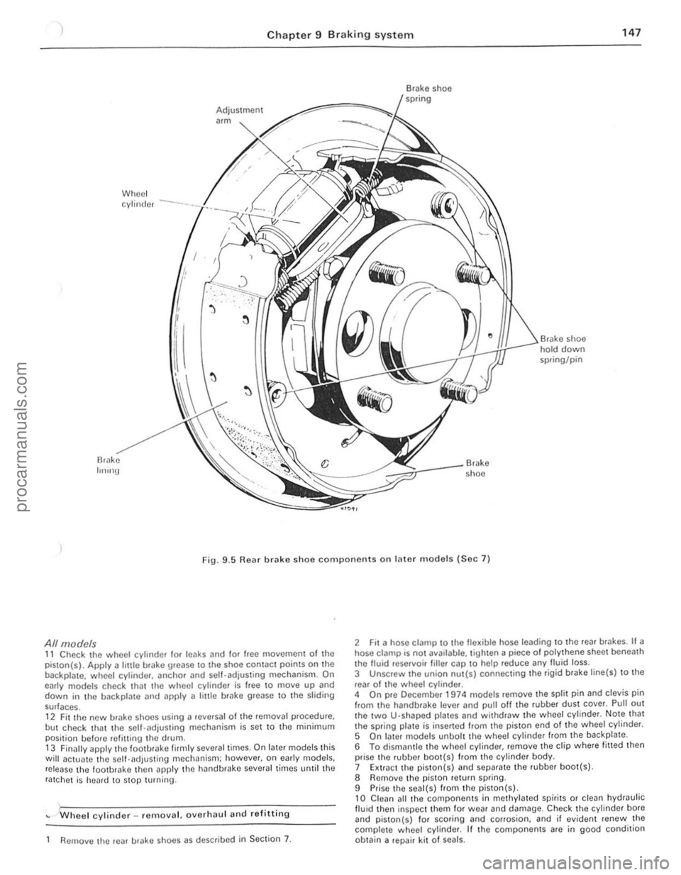
.5 Rear brake shoe components on later m odels (Sec 7)
All models 11 Check the wheel cylinder lor leaks and lor Ioee moyemen t of the
piston(s). Apply a hule brake urease to Ihe shoe contac t points on the
backpla te. wheel cylinde r, anchOr and sell-adjusting mechanism. On
early models check th
but check that the self-.. djusting mechanism is set to the minimum
posi tion belore refilling the drum .
13 Finilily apply lhe loo tbrake firmly several times. On later models this will actua1e the self-adjus ting mechanism; however. on e
Wheel cylinder _ remo yal. oyerhaul and re fitting
Remove lhe rear urake shoes as described in Section 7.
2 Fit a hose clalllp to the fle~ible hose leading to the reaf br .. kes. If a hose ci
5 On I.ller models unbolt the wheel cylinde r from the backplate .
6 To dismantle thO wheel cylinder, remoye the clip where fitted then
prise the rubber boo t(s) from the cylinder body.
7 Extr.lct the piston( s)
9 Prise the seal(s) from the piston(s) , 10 Clean all thO compo nents in methylated spirits or clean hydraulic fluid then inspec t them for wea r and damage. Check the cylinder bote and piston{s) 10f scoring and corrosion. and il eviden t renew the
complete w heol cylinder. If the components are in good condition
ob tain a repair kit 01 seals.
i.
i I
II
j
I ;
procarmanuals.com
Page 149 of 205

)8 Chapter 9 Braking system
8
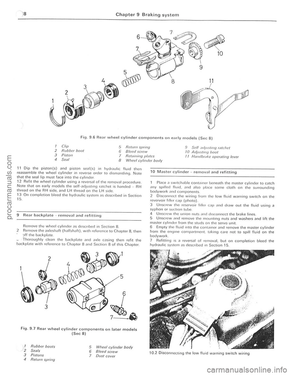
Fig. 9 .6 Rear wheel cylinder component s on "",I y models (Sec 8)
I Cft,} 2 Rubber hoot 3 Pis/oil
5 Relmll SfJflflY 6 Blcell screw 9 Scff ",',uSilll!! wtdll.:/ 10 At/jlls/my boof
4 Seal I Retaming JlI,~tcs II Ullfufb,;,Ac oj/cUlling level 8 Wheel cyhirdcr body
11 Dip the piSlOn(s) and plSlOn SC
9 ROilr backl}lato -rClllovn! (IIHI mfittillg
Remove th ... wheel cylllllier ~s
Fig. 9.7 Re .. r whoel cylinder components on lilter models (Sec 8)
1 Rubber boots 2 Se'lls 3 PiS/OilS 4 Re/vm spring
5 Wheel cylinder body 6 Bleed screw 7 OVSI cover
1 0 MJsle r cylinder -rcmov;11 Jnd refitting
P lace a ~wllcIH'hJe COI11~lIler benem h Ihe mJ$le f cylinde r 10 cmch ,1ny spIlled Ihud ... Mil also place ~on,e cloth on Ihe surrounding hodywork ;lml componems 2 Disco"nect Ihe wirinlJ lrom the low tluid winni,,!) sw,tch on the ,evelvoir 1,lh.1I r:ap (photo).
3 UIlSI:f(lW lill) reservoir 1011111 cap and dr"w out the flui(1 using J syphon or sucl'o" l(,be <1 Unsocw ("u un'on Illl(S IOnd rlist:onncct Ihe b,ake lines. 5 Unscrew lOud r emove (ill) nlolUwng nulS and washers Jnd lilt the mnster cyl",du' hom Ihe Siuds Oil Ih e servo lmll. G Empty llin tlu,d 11010 llie con l,urlcr Jnd remove the master cylinder
from Ihe enU",e comp(lrtmeni. Io1k,ng cllre nOI 10 spill Iluid on the bodywolk. 7 HeliuinU 's II ,eve'slIl of removJI. but on completion bleed the hydraulic syslem IIS (Iescribed In Section 15.
10.2 Disconne cting the low lIuid warning switch wiring
procarmanuals.com
Page 190 of 205

-
) Chapter 11 Bodywork and fitting 189
/~
32 8A I',,~c 0111 Ihe alp 32 an ali(I ,(,mo .. c the console screw 329 Removing the hnndbrake lever boot find be~el
Fig.n.la C lock ro:.,,"ov
32 Centre cOIl~ole·· fUIllUV,,1 ,,,,d refiUinu
IJasic tYlle '.111 Ihe caqll:l 110m ;!lolllni the r'OIlI of t im t:()Il~()lo, thun push the " .J
33 Sunroof piln el -ndjustments
Gap adjustment 1 When closed. a Unp of 5 8 10 6.9 mm (0.2310 027 "') should eXI~t hetwecn thc slIn(oof and (h e CM rool. II;) vmyl roof cover IS lilted. Ih,s gap should he reduced by 1 .78 mm (0.07 Ill). If adlllst'!\(Jnl IS requued. pwceed ns detaIled below. 2 With the sunrool hall open. remove (he sunrool heildhlunll hnlne 3 Close the sUllfool. then pull Ihe hei!dhnll1H hOIll (he Ie." and remove ,I. 1 To ndlust the hOnl 01 the sumoo!. loosen the front Uu,de relillnu1U screws. then whIlst p,essu1!J (he Uuitles IIlwilrds. lighten thc screws. 5 To ;)d,ustthe rear. loosen (he twa h.II1!) screws nt eneh Side of the ,1dlustinU hnsc. thcn p,ess (he reilr shdes mw,uds ,1"d t'Uh!Cn . 6 F,t the hCildllmn(J and hemU",,,,U h,,,ne 7 lithe ild)lIsunenl is slill Incorrect. ,emove (he we,l\hel$I"p from Ille rool panel ;)11(1 hend ,IS mountll1g lIange as necessary
.,.,.'~ ..... ,,--...... ;;
• · .. ···"'·' -·0 . .'--
,"·""",-- 'r
FiU 11.19 Sunroof controllllechanism (Secs 33. 34 and 35)
, . , , , ,
I
,j
procarmanuals.com