clock setting FORD CAPRI 1974 Workshop Manual
[x] Cancel search | Manufacturer: FORD, Model Year: 1974, Model line: CAPRI, Model: FORD CAPRI 1974Pages: 205, PDF Size: 43.75 MB
Page 88 of 205

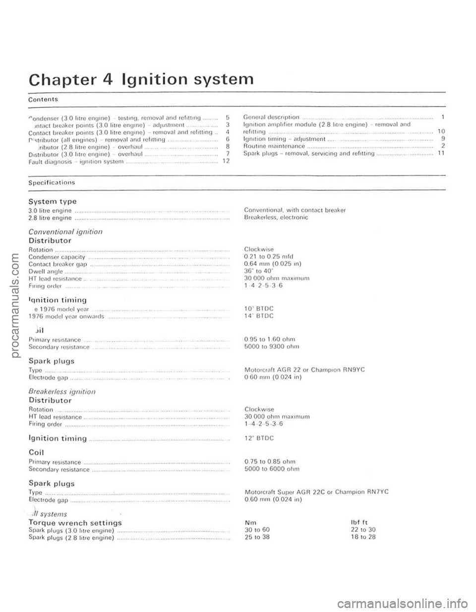
Chapter 4 Ignition system
Contents
"'ondcnsc! (30 Iotre cnUIIlC) teslI llU . removal and rc h1!ln g .... 5 '"tact b.ellkc . POIllIS (3 .0 litre CIlUIIlC) ,lI 11us1mC lll 3 ConlilC ! brCi.ke< POintS (30 lIue cnumc) -Hlllloval fllIIl rclr ninH . " f" '~lnb\llo, (1111 CIl\ Ji llCS) lema",,1 .lIlt! .cll1l1n\) (j nhlllOr (28 lilre Cilomo) -overhalll.. 8 D,stributor (30 h\le cnuinc) overhaul . 7 Faull diagnos is -iUm\loll system. 12
S rICcificin ion s
System ty pe
3.0 lit.e engine 2.8 litre engine
Convent ional ignition
Distributor
ROIDlion Condense, cnp
c 1 !H6 model yC
I',im
Type Elect. ode U
8reaker/ess igllilion
Distributor
Rotation .. HT lead rCSlstn llCe .
Firing order
Ignition timing
Coil
Primary rcs,sWnce
Secondary resis lan ce ............... .
Spark plugs
Type Electrode {jap .
,1/ systems
Torque w rench settings SpD,k p lugs (3.0 litl(l CIl!JUlC) SPD,k plug s (2 8 hl,e engine)
Geller,11 dCSCfll>, ioll 19r1lllon tnnphlicr Inodule (2 8 hire engine) -. emov,l l and 'Ch1tmO ... ......... .............. . IUrlltlon timinlJ -ndJuslmcnl . flOulUl!) Ill;untenancc . Spark plugs -rem Oval, servicing an d .cl'!lu \g ,
ConvcmiOllill. with cantilCl tu cilke. Br eake rlcss. clCCltOnic
Clockwbe 0 2110025 mid
0 .61 mm (002510) 36" t o <10 · 30000 ohm mOlX"U,uU 1 <1 2 5 3 6
10"' B1 DC 11\· BTDC
0!l5 10 1.60 ohm 50001 0 !l300 o h m
M ot
o,,,,,lt AGR 22 o. Ch;lIllp lon RN 9Y C 060 IlHIl (0024 in)
Cl ockw,se 30000 ohm Il1
BTOC
0 .
75100.85 o hm 5000 to 6000 ohm
Moto"ra" Super AGR O .GO mill (0024 in)
N rn 30 to GO 25 to 38
22C 0' ChJlllplon RN 7YC
Ibl It 22 to 30 1 8 to 28
10
9
2 11
procarmanuals.com
Page 95 of 205

94 Chapter 4 Ignition system
i ' .
. --8 2A Removill{J the IllnSlre dust COve, (28 hl'c Cllume)
./ :,
, , ,
(\. I ,
" 'v
J 2C W'''I1!j connector i'Uld seCUJlIlg screw (lHOwS)
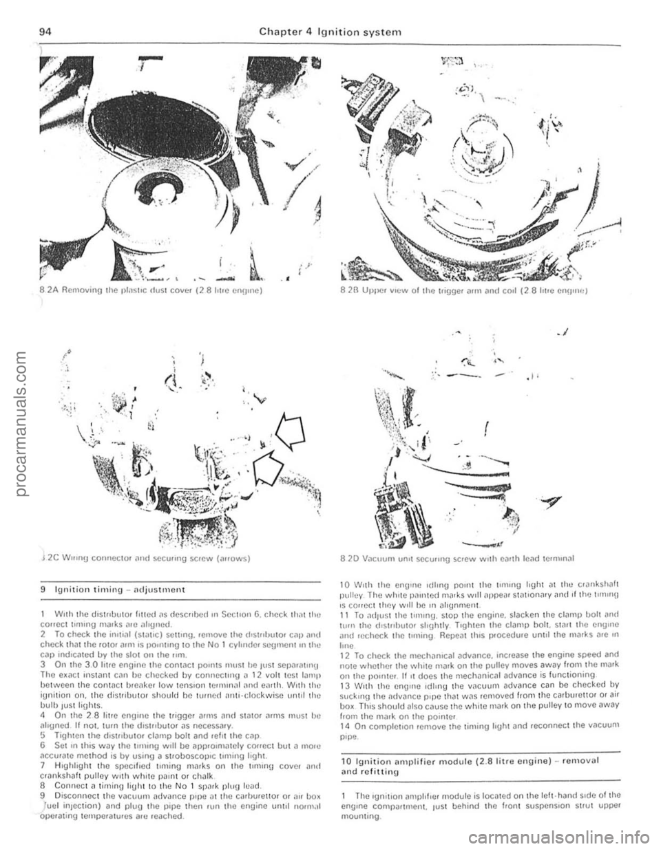
9 Ignitio n timing -adjustment
Wnh the (.lIs\"OuIO' III!Cd ilS dcscllbed OIl SectIon 6, check Ihilt 1Ill! COHCCt llllllng m;l!ks "'0 ;1119110d. 2 To check the ;1111,,11 (5 t;1I,e) setting, .emovc the (I'51"lIu I0' c;lll [11l\( check IhJllhc rOl0' ;lIm IS PO"1I1119 to the No 1 cylmdc. scgmon!.n the Cill) rndlcmed by the sial on the 11m. 3 On the 3.0 lUre engIne the cont,le l poullS ll\u~1 he ,ust SCI)ilril\U'!J Tho e~ilCt Instant C,1" he checked by connect"'u il 12 vol1 lest lamp between the contilC, brcilke r low tenSIon Iemur),,1 iUl(t O,"lh, W,th the iUnilion Oil, tho d is trlbuto. ShOllld be turn ed nrl\,·clockwisc unlol lho bulb luSlligh(s. " On (he 28 li(re enuule the ("gger arms and stator ;HIllS must bc aligned It not. (um I he (hst"bulOr as necessary . !:i Tighten the (hSI"buto. clamp boll and .ehl the cap 6 Set In thIS way the lUlling WIll be alll)'Olmalely co
8 2B UtJlle. vIew 01 the l.imJer Mrn .lrld Call (28 lIt Ie enU"Wj
.1
,I,
.. .."
8 20 Vacuum un.1 sC(:u"ng screw WIth e')Hh lead termmal
10 W,lh Ihe enij1l1e I(lIrng pornt thc \fmlng hgh( at the cr",lksholl1 pulley The wh,le 1),1mte
12 To check the mechanrcat adv.1nce. Increase the engIne speed and note whelher the wh,te malk on the pulley moves away Irom the mark on th e pOInter . 11 It docs the mechanical advance is lunctioning 13 W,th the enOlile Idlmu the vnCU\ Jm advance can be checked by suc kIng the oldv~ncu pIpe that W.1S removed from the carburellOI o r air box ThIS should also c.Juse the while rnark on the pulley to move away horn the mar k on the pointer 14 On completIon remove Ihe timlllU hght and rC(:onnec lthe v.1CUUIll pIpe
10 Ignition illlllllifier module (2.8 l i tre enuine) -removal and rClittinu
Thc Iunitlon illl\J}l lflcr module is locmed on Ihe left· hand SIde of the engIne COnlpar tment. tUSI behind Ihe hOnt suspenSIon strut upper mounting.
procarmanuals.com