coolant FORD CAPRI 1974 Workshop Manual
[x] Cancel search | Manufacturer: FORD, Model Year: 1974, Model line: CAPRI, Model: FORD CAPRI 1974Pages: 205, PDF Size: 43.75 MB
Page 47 of 205
46 Chapter 1 Engine
35 Vnlvo clearances -checking lind adjustment
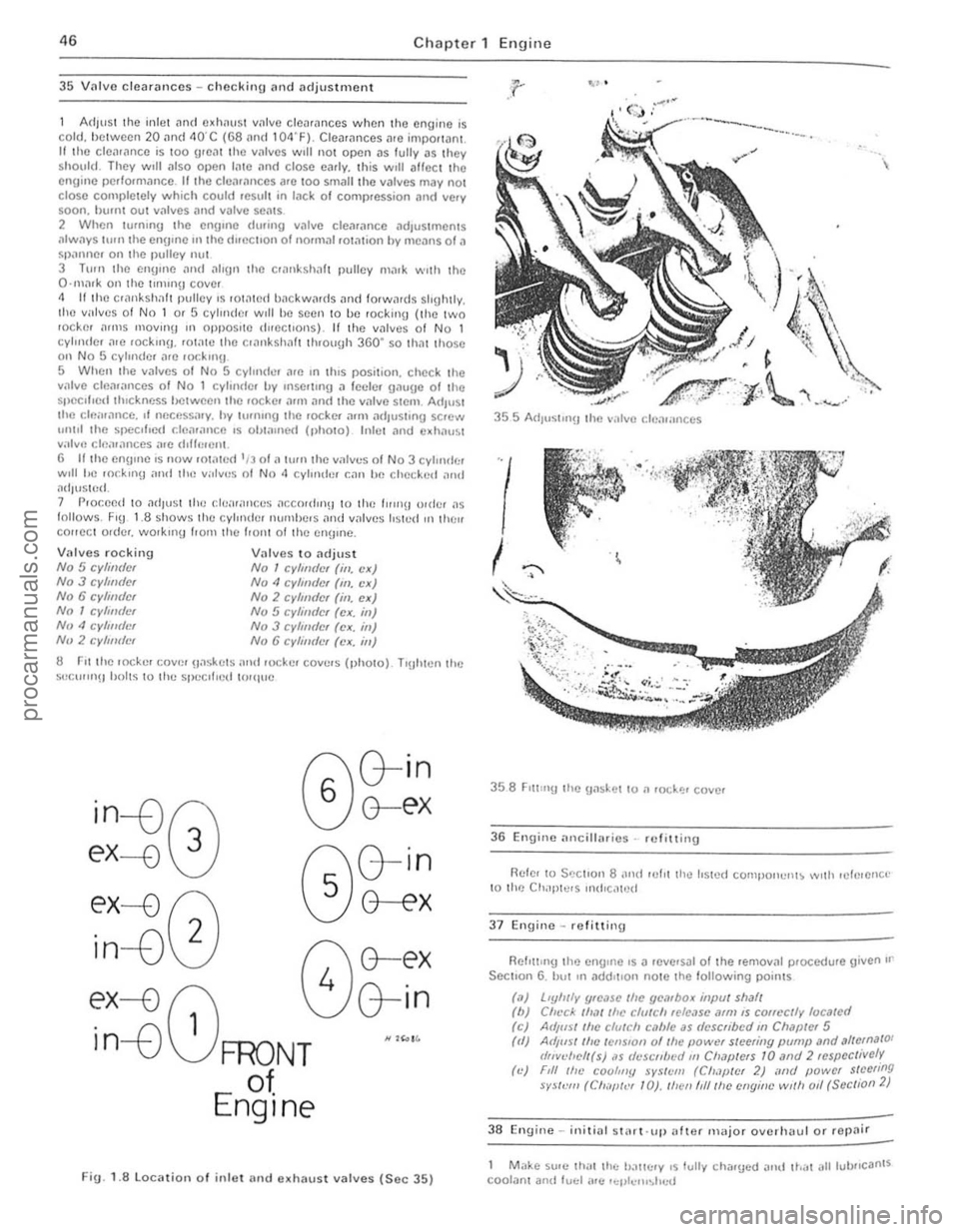
Adll'S 1 the inle t Jnd c~h"ust villvc clcnrnnce s when lho engine is cold, he lween 20
S llcclfled thickness hetween Ihe lock e ' ,'1111 :lnri the vnlve stem. ArlluSt the cl("II:lncc. It necess,"Y. hy hlmong the lOCkCf null ndJushn!,l screw 1011111 the speCified cfenlnnce IS obtained (1Ih010) Inle t nnd edlo1u~t v;,lv'~ cle;IIances a.e rh(/.!.ell\. 6 II the engine IS now IOt,~tcrl '/301 II hun the v.1lv .... s 01 N o 3 cvlll"l!":r w,1I he rockul~J ,111<1 the v;olv"s 01 No ,I CVlll,!s,!r r..1I' he checked ,lnd I1dJus t()d .
7 Proceed to ;"Idlust Ihe cf":II:II'CCS .1I:COrdrn\1 1 0 th" '''rnO o!(ler ;"IS lollows. F,U 1 .8 shows the cvlOildel IHHllhe.s "nd valves Irsl .... d OIl tllell eou eer o.rlcr. wo,k",U Ilorn Ihe llOlIt 01 the engone .
Valves rocking No 5 Cldimler No 3 cylm(lcr No 6 cylmticr No 1 cylll/tier Nu 4 CylllltilH Nil 2 cylll/tie,
Villves to ndjust No 1 cyltll(lef (ill. ,'x) No" cyllmler (III. ,'x) No 2 cylm(lcr (ill. ex) No 5 cylilltier (cx. ill) No 3 cylmdcr (ex. IiI) No 6 cylimft'r (ex, ;n)
8 r-11 the rock er COV~!' U,1skcIS ;IIHI rockc. covers (photo). T 'Uh ten the S(!C'''rI1 !) holts to Ihe speCi fied twqllc
~:j?0
ex-0
(;\G-in
~G-E'X
r:\G-in
0G-E'X
ex---{) 8 4 G-in
. n 1
in--v FRONT "'""
of
Engine
Fig. 1.8localio n of inlet
l
I
36 Engine anciIiMies·· ref itting
Rcle' 10 SCClrOIl 8 "ud rul,t the Irsted COllllJor""'t~ \Vllh rele,erlce to Ihe Chaple,s mtl'C,lh)(!
37 Engino -refitting
Rcf,wn!) the cngrne '$ D reve,sDI 01 the ,emoval procedure given or Section 6 . hili III Ddd,uon note Ihe lol/owing pOin ls
(,l) (b) ,oj (II)
(c)
Llyfuly (frc,lSC fhc yembox illfml shaft Ch~'ck 111,11 /h,· clulch rcle,'se ,11m IS correctly loca/cd AdIIlS/ Ihe CfffU;h C,l"'C as (Iescfibed til Chilpler 5
Ad,US/ Ifle tcnSfo n of Ihe powef sleell;IY pump ilnd ,,1/emilIO ' "nvd1ell(s) ,IS (/eSt'nlwtilll CII,lplefS 10 alld 2 respcc/ively Fill Ille COQIIIUI sySlem (Ch.lp/er 2) "1/(1 powcr stecling SYS/VIII (ell"!!I,.:, 1 0). Illen I,II/lic Cflgine w,III 011 (Scc/ioil 2)
38 Engine -in,t;"l stMt 'lIl) ,,/ter major overhaul or rcpnir
M"ke su,e thai th.:: h:l1tc1y ,$ fuliV cha,u.::O '!IId Ib,"" alliub rrcafl tS coolant and lucl ,lie '''III''''',sl,..,,,
.... ~ __________ .................................. r
procarmanuals.com
Page 59 of 205
,
I ;
I
i
, . I
)
58 Chapter 2 Cooling system
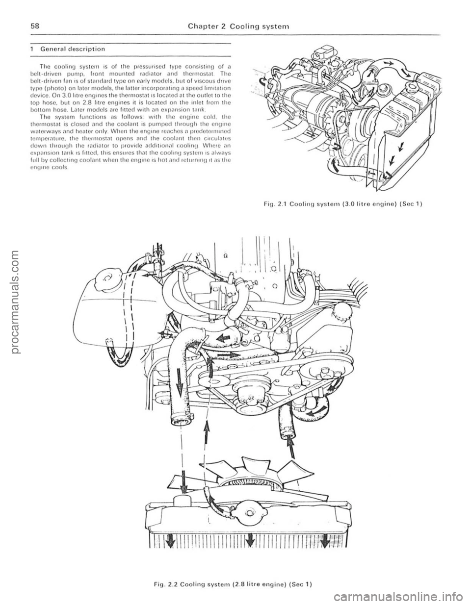
Goneral descriptio n
Tho coo1inU sys tem IS of tile flfCSSll"sc d type consiSling of 11 helt·driven pump. h0l11 mourllc d .ild,ator and thermOSI"! Th e hClt·rhrvcn 1,111 IS of SI;mf!ard type on carly models, bllt of VISCOUS drive IYlle ( l) holO) on lalC I models. the lallci jllCOrPO'ilUllg iI speed 1I0)'I<1110n (I(!vkc, On 3.0 hue cnOllles t he IhcollOSlill IS IOCillcd (I( tho,'! 011 tiel to tl lC tOp hose. but on 2.8 htre engines i, is localcd on the 11110 1 hom 1ho baliom hose . Lmc. models
Fin. 2 .1 Coolinu systelll (3.0 lilro cngine) (Soc 1 )
Fig. 2 .2 Cooling syslcm (2.8 litre engine) (Soc 1 )
procarmanuals.com
Page 60 of 205
)
'tz
Chapter 2 Cooting system 59
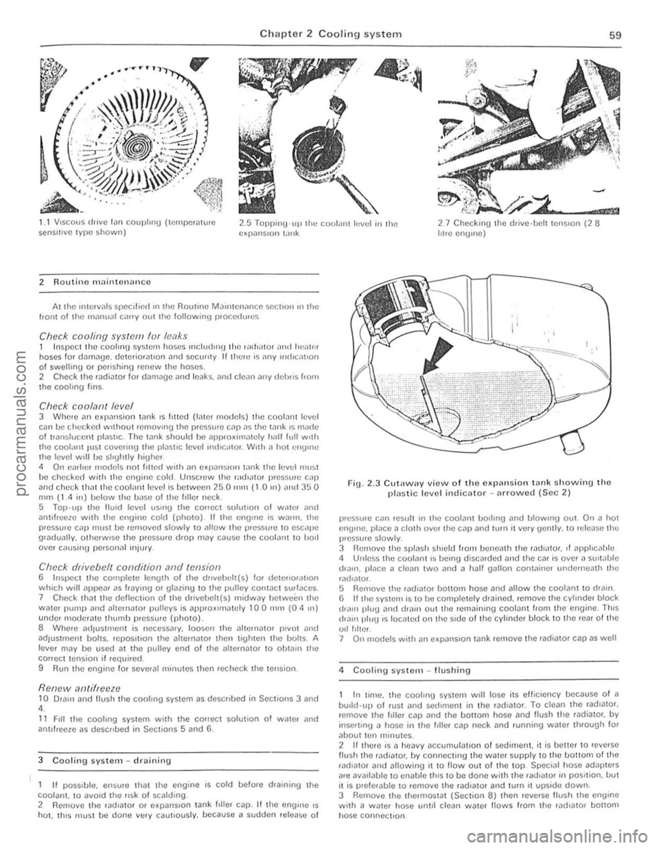
1 I VISCOUS (IPlVC I,m coupling (I,~mpc,alu,e sensitIve 1VIle shown) 2.5 Tuppill\l -lIplhc COlllilll1 h,vel in the c~J)alls,on \;lI\k 27 Checkin U the drive-belt IClls,on (28 hire CIlUulC)
2 Routino Illaintcnanco
Altho ,n1C, ... "ls SPOC""]!! utlhe Rouhnc M .. "UcnanCf! SOChOr! on Ihe 110111 01 the m;uu,a1 c;lrIy oul the lol1oWl!ljl p.occduoes
Check cnoling syslcm lor /c,1k.~ 1 In spe cl Iht! coolin!! sysh),l) hose s 'llcludlll!) the ,adIOiIO' :,"<1 Iwate. hoses for damage. detcriOlllll0n i1nd sccullly If Ihelt) is I'Irly IOulle;1I'01] of swelling 01 p
COf/ec t tension If .equir e d .
9 Run the enuine f o r severlll minutes Ihen rec hec k t he lension.
Renew,1/Jtilreeze 10 O.am i1nd flush Ihe CO(lhng System as descrlhed in Sections 3 and 4 . 11 F,II the coollllg system With Ihe correct solullon of watel and amlf,ccle as desc"hed in SeClions 5 and 6 .
3
Cooling sysl e m -drai"inU
If pOSSIble. ensu,e thilt the engine IS cold belo.t! d.al"i"lJ Ihe cool ant. 10 aVOid the fisk of scalding.
2 Remove Ihe .adlatOf or expanSIon tank IIlIe. cap. If the eflUlnc IS hot. Ih ls must be done vl;lry caul,ously, because a sudden release 0 1
Fig. 2.3 Clltawa y view o f Iho expan sio n tlln k showin g tho plastic lovel indicator -tH rowed (Sec 2)
P'".'·S5U'0 CilIl ,esull II. the cool(lnl !.>oIling i1nd blOWing Oul. On ,1 hot enUlIle. plilce iI cluth ove, the caf} and lurn il ve. y uently. '0 release tim p,ess\lIe slowly. 3 flel110ve the SplilSh shield frOI11 b enomh the ra(II;IIOf. of i1pplrcilble
" Unless !he coolilnt IS beinu discarded and thc ca. 's over (I slilt illJle
d'illl1. ,,'"ce a deiln IWO i1nd a half gallon Conl;1ine. underneath the ,adlaIOl. !) Rel110ve the radlatOl bOllom hose lind allow the coo'al11 10 drili" . 6 If the SyStel1'IS to be completely d,ained. rcmove the cyhnde. block d.;1I1' pluU and draIn oul Iho .emainlng coolant hom tho engine . ThiS d'illf' plug IS locilted all the s,de of the cyl inder block to Ihe rear of the oiliolicr. 7 On 1I10deis wilh all eXJ}ilnSlon tank 'emove the rad.alO' cap as well
4 Cooling systom -ftushing
In IUlIe. !he cooling syStel11 Will lose ils efficiency because o f a bu,ld'lIp 01 .uSI and sedunen t in the radiator. To clean the .adliltol. .emove thc IllIer Cill) i1nd 'he bOllom hose ilnd !lush Ihe radialo" by inse.llng a hose in Iho f,lle. car> neck i1nd funninu Wille. th.ough fOf about tr.m I11mules . 2 If Ihere is a Ilea vy aCCUmuliltlOn 01 sediment. it is betler to .eve.se
flu sh Ihe .adl~tor. by connecting the water supply 10 Ih o boltom of the rilclmof alld allowinu II 10 flow oul of the tOIl. Speclnl hose adapters arc avai lable to enahle thIS to be done w ith the rild.ator In I)OSllion. but It is p,efe.able '0 removc the lad,ato. and tum il upside down.
3 Remove t he thernlos,a, (Section 8) then .eve.se lIush Ihe engine wi,h a W1l1e. hose u n lll clean waler flows from the .ndlat Of bottom h ose connectIon.
procarmanuals.com
Page 66 of 205
15 Fau lt ui(l9"0SiS ~ cooling system
Sympt o m
Overhe
loss of COOI,llll
...
Chapter 2 Cooling systern
Reason{s)
Insuff ic ienl coolant Drivehel t slrppinu R;JdralQr core btockcI .1. or H"lIe rpSI"tled Air lock in cool lnll SySWIl1 W mer hose Coll.1psed, or linked, ''''red",\) flow TherllloSI
65
procarmanuals.com
Page 70 of 205
)
-
Clwpter 3 Fuel
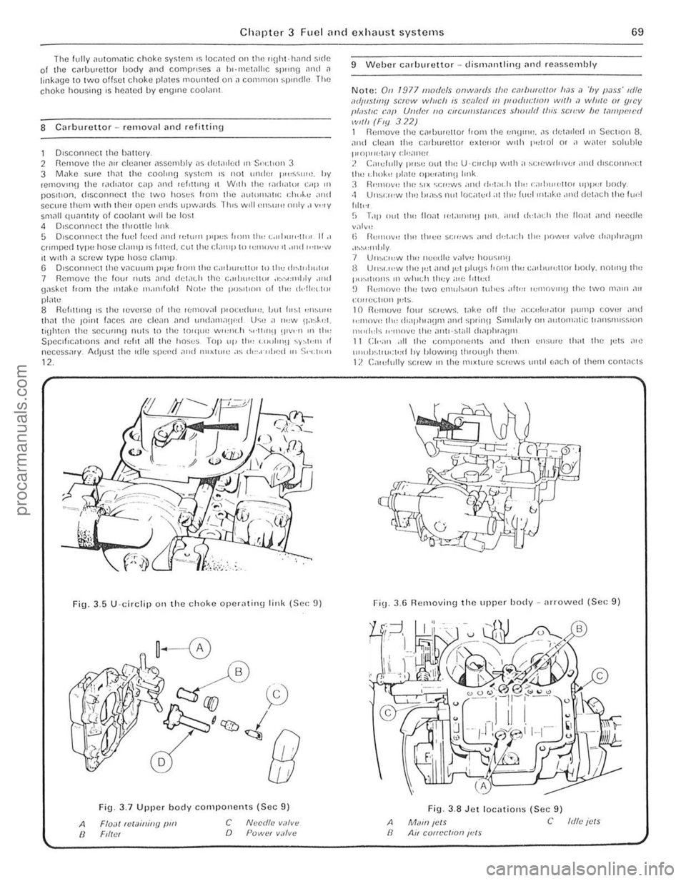
Fig. 3,5 U·circlip 011 the choke operatil\g link (Sec: 9)
A /I
Fi9 3_7 Upper body components (Sec 9)
Flo,lI telaininy pm Ftll.'t c o NlJcdto V;I/V(!
POWCI v.1lvc
9 Weber Cilrhurettor -dismilntlinu [lnd reas~ernhly
Note: On 1977 mod(!/s onw,lf(II /lIP. cmlll/id/ot 11,15 ,1 '/Jy PilIS' tdle IIdIItS/IIIY SP~'W willch IS sc,l/r:iI //I l!lodl/cllOn wl/h <1 willie (}f ljlCY 1,/,'sIIC (:,11' UlI(ler /10 CItC(ff!!s/a/lces should {/II.~ SCI('"W h e /,)t!J/JlNl'd wi/h (Fly 322) 1 R(!II1Ov(! the C.1,h"n;llor I! O"l th e ':Ol!)""' . ,1~ dr;w,lp.oI ,n Section 8. an d cl(!,lIl th.) f:ilrl""etlor extC"Of w'lh 1'.,['01 or a walt' soluhle t"OI",,:l;\,y 1'/,,;)11(:1 J. C;, rdully I"'S" 0,,1 Ihe U'CIIClrp w,th a hC,(lWII"v" •• lIul ,h~COIUlo:cl til" '.ilok" pl"w oj)l:(allnulrnk :I 1\""10\"" tire ~I X ·,,:,,'ws ;'"It ,i,-(;" .h II" , GIl1"""llor "Ill"" body. ·1 Uns';",w llr,) h'n~s nul locnl"d:ot th" ((",I ,nwk,) .'nd d el.1cll Ihe flU'l
Iolt"1 (; T"II Ollt tlo" lIo;i! ,,,t.1"lII'!J pm. ;,nd dd.1{,1r II,,) 110;11 ,Hl d needh~
v:otv" I, R"",,,v,, tlon th,c" ~c,,:ws and d"t.u:1r tlw po","", valvc d';lpl"a!)1ll .'~h,,"'tJly 7 U"hl:",W thn ncedle ~"Iv" ho,,~,nu 8 U"suo:w the It)( and Io:t pt"\Js I. o r" til" c."jJ\""l1m Imdy. not"l\) th .. , p"~.'I'o"s III wh",h 11,,;y ;0,(, f'lll:d ~) I~l"ll()v" (h" two cn ,"b,on luhes ;011'" ,,,'IIOVIII\) the two lll,lIn "" l"II rt<.:t,on t,;ts 10 1l<:!lIUVC lorn sr.'l:ws. t;JkC nil II", ,1co:"I,;r.lto , j)"Il'P co"", ,,,,d ,,,,,,,-.vOl ttl<, d',Ij,lua!l1l> ;Hld 5P(in'l SUlul,,
Fi\j. 3.6 Removing the upper h ody -nrrowed (Sec 9)
A II
Fig. 3,8 Jet locatiolls (Sec 9)
Mwn ICIS C Idlc ICIS Air COtt~'CIIOIl ;"IS
procarmanuals.com
Page 194 of 205
Chapter 11 B odywork an d fitting 1 93
)~--------------------------~-- ------------
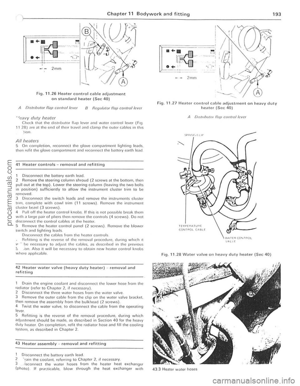
Fig . 11 .2 6 Heilter control cil blc 1Hljus tm ent
on SlHn (IMd heilter (S ec 40)
A (),.\·/"UlI/Ot flajl COII/ro//aVllr 8 I/Cgll/;I/O( Il.7p con/fo/h'vt'f
"'!ovy dilly IIfHltOf Chl.-r.k thilt Ihe d'Slflhutor 1I"p levc. ,HId WilIC, cont.ollcve. (FlU 11 28) we 011 Ihc cnd ollhl)" Ir,"vel ilnd clamp Ihe oulC, cablcs "I \IllS lIon.
AlllwMCfS 5 On complct ion. reconrWC I Ihe ulove comp;lr llllent liUhtinU leads.
Ihen lelil Ihe Ulove COllll)nltrllell1 nnd reconnet;1 Ihe hnllelY emlh len {1
41 H OMe r controls - removal and refittinu
1 Disconnect Ihe ballery eimh lend. 2 Rcmove Ihe s teer ing column shroud (2 screws D tthe bOliO",. then pull oul .lIlhe lOp). Lo wer thc stee.ing column (lel\Ving Ihe twO bOltS in position) sufficiently to ullow t he inst.umenl cluster I rim to be remOve d. 3 DIsconnect Ihc switch 10MIs ;lnd remove the instruments cluSIO' t"m. COllll)lot e with cowl "im (11 screws). Rcmovc the instrumont clusle r l!clOI (3 scrcws). 4 Pull oil Ihe hOiltor control knobs. II t his IS 1I0t possIble I>
.. hc neccssmy 10 adjust th e callies. as dl.'SCfllled III the p.evlous ::. .on Also it w,1I be necessary to obtall1 new hCille. control knobs where npphcable.
42 HCHte r
water villve (hellvy duty heater) -IC lll oval an( 1
refittin g
Drilin
the engine coolant ilnd dlsconncct tho lowe. hosc !rom th c ,aulato. (,efe. to Chapter 2. II necessary). 2 Disconnect Ihe th.ee water hoses f,olll tho Wille. valve. 3 Removo the OUWr cilble from the clip on the WilWr v~lve bracket.
Ihen lenlOve the assembly from the bulkhead (2 screws). 4 Twis t the wate r valve. to disconnect the cable IrOI11 the operilt ing
l ever .
S Relilling is Ihe reve'so of the removal p.occdure. during which ~dJustl\lcnt should be m~do. as described in Section 40 fOf the heavy duty healCf On completion. re li t the rudiutor hose and fililhe cooling SYSt(:rll . us described in Chapler 2 .
43 Heater assembly -re mova l and re fillin u
1 DlsconnOCl lhc tJiltH:ry ea.th ICild. 2 -,,,in the COOIIlI1l. rei!;fliny 10 Chllpte. 2. II neCCSSilry. 3 sconnect th e Wiltcr hoscs from the hoale. he;!t e.chanuc. (phOtO). II I>
- ' = 1 --·-~··""I c,
'1,:-1
F ig .
11 .27 Heale r COl\trol cilhle ncJju stm ont on heilvy cJllty hl"latot (Sec 40)
A /),., ·{n/w/III If,}!, CQII/lo/ft'vct
Il"'·I·"1>.1 VU[ CO""'OL U·OL(
".."Tt"CO""'OL -NIL\[
Fig. 11.28 Willer varv e o n heavy duty heilter (Sec 40)
43.3 H eiltel water hoses
i , , . ,,
"
procarmanuals.com
Page 202 of 205
inlet manifold - 83
main system components remova l and refilling -80 m~intenilnce, routine -79
specificiltions -67 to rque wrench settings -67 Fuel pump carburettor system cleaning - 68 re moval and refilling - 68
testing -68
fuel inject ion system removal and refining -80 Fuel system (carbureUor) accelera tor cable -74
accelerator shah and pedal - 75 air cleaner - 68
carburetlor -66, 68 to 73
description -67 e~ haust manifold - 76 lault diagnosis -85 luel pump -68 fu el wnk -73, 74 fu el lan k fille r pipe -74 fuel tank sender unit -74 inle l manifold -75 mainte nance, routine -67 specifiCiltions -66 torque wrench senings - 67 Fue l tank cleaning and repai r -74
filler pipe removal and re fi\ling .-74 remova l and refilling -73
sender uni t removal and ref il\in g -74 Fuel tank sender unit (fuel injection models) -83 Fuses
G
general -220 specifica tio ns - 199
Gearbo~ see Manual gearbO K Gudgeon pins - 37. 52
pdbrake adjus tment -153 cable(s} and rod removal and refilling 155 lever removal and refitting -154
warnin g hght switc h -225 Headlights alignment - 212 assembl y: removal and refilling ~ 211 bulbs renewal-2 13 Heater assembly: diSI11(lntting and reassembly 8ehr - 19 4 Smiths standard and heavy duty -196 assembly: removal and ret.tting -193 contlols
adjustmen t -192 removal and refilling ~ 1 93 water valve (heavy dUly heater)
removal and re fitting - 193 History o f tho nlodal-5 Horn faul t tra cing . remova l and refilling -220 Hubs, front
bearings renewal -162 removal. ret lu in g and bearing adjustment -16 1 Iraulic systam (brakes) bleed ing - 152 pipes and hoses removal and refilling -151
Index
Ignition switch and lock -224 Ignition system -87 el seq Ignition sys tem amplrlier module (2 .8 l i\(e mode ls)
r emova l and refilling - 94
condenser (3. 0 litre models) -90 COntact bre aker points (3.0 litre models) - 89
description -88
dis tributo r -
90. 92. 93 fau lt diagnosis -96
firing order -87 mainteMnce. routine -88
spare plugs - 91. 95 speci fications -87
t im ing -94
torque wrench settings -87 In strument cluster ill umina tion switch -224 removal and refitting _ 221 Instrument voltage regulator removal and refilling -226 Interior lamp and bulb
removal and refilling -217
J
Jacking -7
L
lubricants and fluids recommended - 17 lubrication chart - 17 lubrication system
M
2.8 litre engine -39 3.0 litre engi ne -53
Main and big·eOld bO(lrings e~amination and renovation -37, 52 Main bearings (3.0 litro engine) removal - 51 Maintenanco , routine bodywork and fillings d oor ch ec k straps security check - 16 locks, door chec k Straps. tuellilte r C
h andbrake linkage lubricat ion -16, 144
h ydraulic fluid levul check /lap up - 16 . 143 hydraulic flu id renewal -16. 144
line s and hoses check -16
pads ilnd shoes we." check -16 , 14 3 servo check -16 . 144 vacuum hose check -16 Clutch adjustment chock -16, 98 cooling syslem
coolan l leve l chec k/top up -16, 59 coolant renewal -16, 59 drivebelt condl tion/wnsion check -16, 59 leaks check - 59 electrical system
ballery elec tro lyt e leve l cheek /top up - 16. 200 equ ipmen t opera tio n check -16. 200 headlamps cleaning -16
253
'i
'" , '.;.l
•
procarmanuals.com