FORD E-250 2001 Owners Manual
Manufacturer: FORD, Model Year: 2001, Model line: E-250, Model: FORD E-250 2001Pages: 224, PDF Size: 1.99 MB
Page 131 of 224
Fuse/Relay
LocationFuse Amp
RatingPower Distribution Box Description
F Ð IDM Relay (Diesel Only), A/C Clutch
Relay (4.2L Only)
G Ð PCM Relay
H Ð Blower Motor Relay
J Ð Horn Relay
K Ð Fuel Pump Relay
* Mini Fuses ** Maxi Fuses
Relays
Relays are located in the power distribution box and should be replaced
by qualified technicians.
CHANGING THE TIRES
If you get a flat tire while driving, do not apply the brake heavily.
Instead, gradually decrease your speed. Hold the steering wheel firmly
and slowly move to a safe place on the side of the road.
Spare tire information
The spare tire for your vehicle is stowed under the rear of your vehicle
(except cutaway and stripped chassis models).
To remove the spare tire:
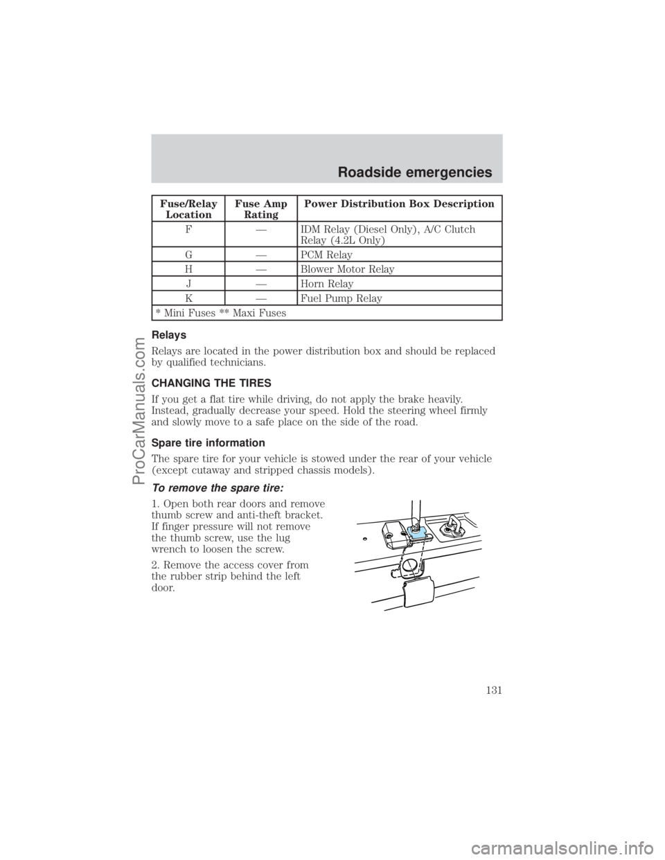
1. Open both rear doors and remove
thumb screw and anti-theft bracket.
If finger pressure will not remove
the thumb screw, use the lug
wrench to loosen the screw.
2. Remove the access cover from
the rubber strip behind the left
door.
Roadside emergencies
131
ProCarManuals.com
Page 132 of 224
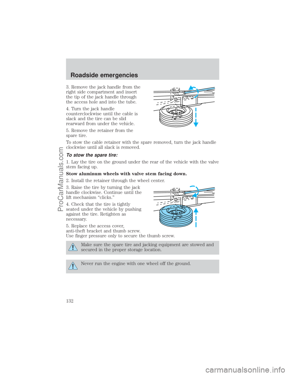
3. Remove the jack handle from the
right side compartment and insert
the tip of the jack handle through
the access hole and into the tube.
4. Turn the jack handle
counterclockwise until the cable is
slack and the tire can be slid
rearward from under the vehicle.
5. Remove the retainer from the
spare tire.
To stow the cable retainer with the spare removed, turn the jack handle
clockwise until all slack is removed.
To stow the spare tire:
1. Lay the tire on the ground under the rear of the vehicle with the valve
stem facing up.
Stow aluminum wheels with valve stem facing down.
2. Install the retainer through the wheel center.
3. Raise the tire by turning the jack
handle clockwise. Continue until the
lift mechanism ªclicks.º
4. Check that the tire is tightly
seated under the vehicle by pushing
against the tire. Retighten as
necessary.
5. Replace the access cover,
anti-theft bracket and thumb screw.
Use finger pressure only to secure the thumb screw.
Make sure the spare tire and jacking equipment are stowed and
secured in the proper storage location.
Never run the engine with one wheel off the ground.
Roadside emergencies
132
ProCarManuals.com
Page 133 of 224
Tire change procedure
Preparing to change the tire
To prevent the vehicle from moving when you change a tire, be
sure the parking brake is set, then block (in both directions) the
wheel that is diagonally opposite (other side and end of the vehicle) to
the tire being changed.
1. Park on a level surface.
2. Activate the warning flashers.
3. Place the gearshift in P (Park)(automatic transmission).
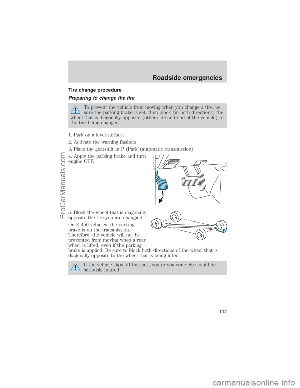
4. Apply the parking brake and turn
engine OFF.
5. Block the wheel that is diagonally
opposite the tire you are changing.
On E-450 vehicles, the parking
brake is on the transmission.
Therefore, the vehicle will not be
prevented from moving when a rear
wheel is lifted, even if the parking
brake is applied. Be sure to block both directions of the wheel that is
diagonally opposite to the wheel that is being lifted.
If the vehicle slips off the jack, you or someone else could be
seriously injured.
Roadside emergencies
133
ProCarManuals.com
Page 134 of 224
6. Remove the spare tire and jack
from the storage location.
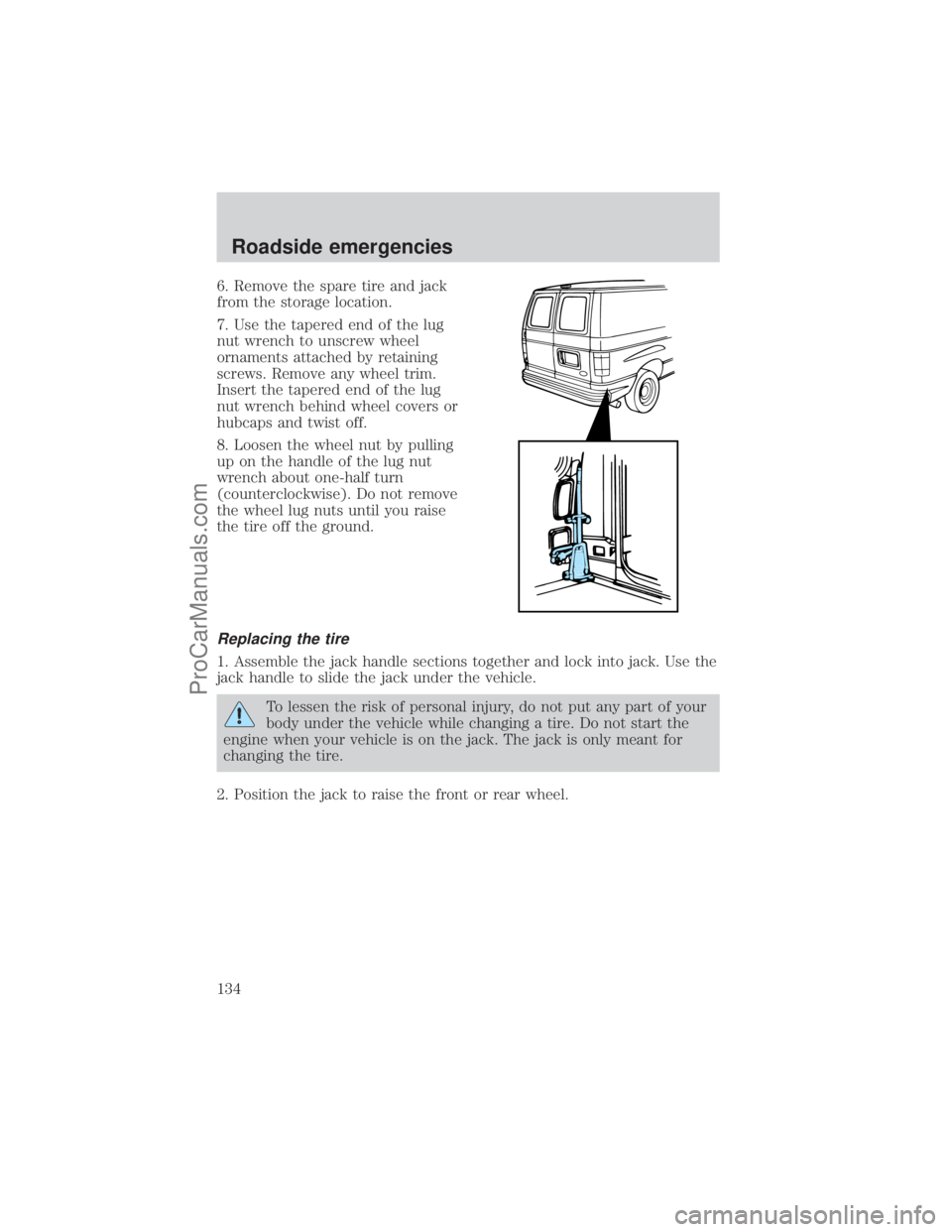
7. Use the tapered end of the lug
nut wrench to unscrew wheel
ornaments attached by retaining
screws. Remove any wheel trim.
Insert the tapered end of the lug
nut wrench behind wheel covers or
hubcaps and twist off.
8. Loosen the wheel nut by pulling
up on the handle of the lug nut
wrench about one-half turn
(counterclockwise). Do not remove
the wheel lug nuts until you raise
the tire off the ground.
Replacing the tire
1. Assemble the jack handle sections together and lock into jack. Use the
jack handle to slide the jack under the vehicle.
To lessen the risk of personal injury, do not put any part of your
body under the vehicle while changing a tire. Do not start the
engine when your vehicle is on the jack. The jack is only meant for
changing the tire.
2. Position the jack to raise the front or rear wheel.
Roadside emergencies
134
ProCarManuals.com
Page 135 of 224
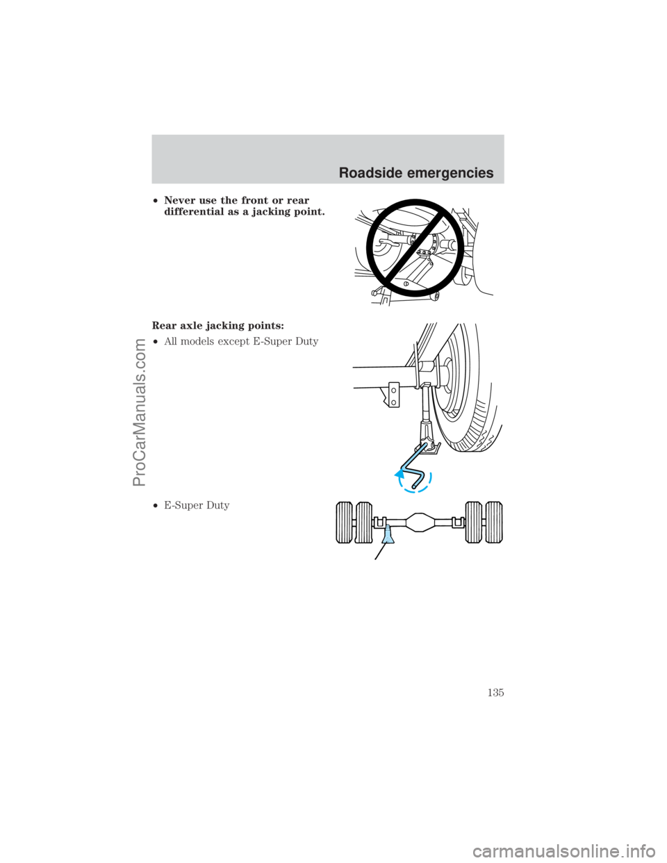
²Never use the front or rear
differential as a jacking point.
Rear axle jacking points:
²All models except E-Super Duty
²E-Super Duty
Roadside emergencies
135
ProCarManuals.com
Page 136 of 224
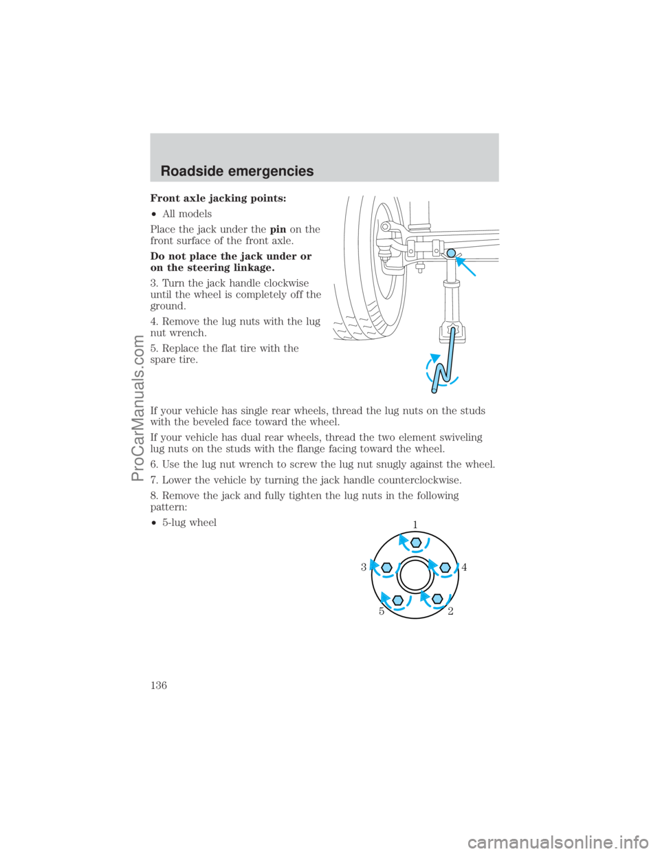
Front axle jacking points:
²All models
Place the jack under thepinon the
front surface of the front axle.
Do not place the jack under or
on the steering linkage.
3. Turn the jack handle clockwise
until the wheel is completely off the
ground.
4. Remove the lug nuts with the lug
nut wrench.
5. Replace the flat tire with the
spare tire.
If your vehicle has single rear wheels, thread the lug nuts on the studs
with the beveled face toward the wheel.
If your vehicle has dual rear wheels, thread the two element swiveling
lug nuts on the studs with the flange facing toward the wheel.
6. Use the lug nut wrench to screw the lug nut snugly against the wheel.
7. Lower the vehicle by turning the jack handle counterclockwise.
8. Remove the jack and fully tighten the lug nuts in the following
pattern:
²5-lug wheel
1
4 3
2 5
Roadside emergencies
136
ProCarManuals.com
Page 137 of 224
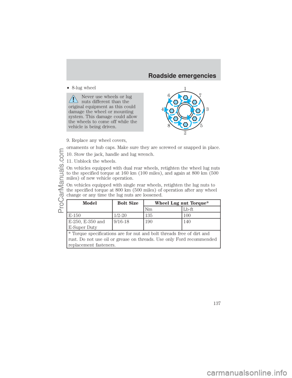
²8-lug wheel
Never use wheels or lug
nuts different than the
original equipment as this could
damage the wheel or mounting
system. This damage could allow
the wheels to come off while the
vehicle is being driven.
9. Replace any wheel covers,
ornaments or hub caps. Make sure they are screwed or snapped in place.
10. Stow the jack, handle and lug wrench.
11. Unblock the wheels.
On vehicles equipped with dual rear wheels, retighten the wheel lug nuts
to the specified torque at 160 km (100 miles), and again at 800 km (500
miles) of new vehicle operation.
On vehicles equipped with single rear wheels, retighten the lug nuts to
the specified torque at 800 km (500 miles) of operation after any wheel
change or any time the lug nuts are loosened.
Model Bolt Size Wheel Lug nut Torque*
Nm Lb-ft
E-150 1/2-20 135 100
E-250, E-350 and
E-Super Duty9/16-18 190 140
* Torque specifications are for nut and bolt threads free of dirt and
rust. Do not use oil or grease on threads. Use only Ford recommended
replacement fasteners.
1
3 4
27 6
5 8
Roadside emergencies
137
ProCarManuals.com
Page 138 of 224
JUMP STARTING YOUR VEHICLE
The gases around the battery can explode if exposed to flames,
sparks, or lit cigarettes. An explosion could result in injury or
vehicle damage.
Do not push start your vehicle. You could damage the catalytic
converter.
Batteries contain sulfuric acid which can burn skin, eyes, and
clothing, if contacted.
Do not attempt to push start your vehicle. Automatic
transmissions do not have push-start capability.
Preparing your vehicle
When the battery is disconnected or a new battery is installed, the
transmission must relearn its adaptive strategy. As a result of this, the
transmission may shift firmly. This operation is considered normal and
will not effect function or durability of the transmission. Over time, the
adaptive learning process will fully update transmission operation to its
optimum shift feel.
1.Use only a 12±volt supply to start your vehicle.
2. Do not disconnect the battery of the disabled vehicle as this could
damage the vehicle's electrical system.
3. Park the booster vehicle close to the hood of the disabled vehicle
making sure the two vehiclesdo nottouch. Set the parking brake on
both vehicles and stay clear of the engine cooling fan and other moving
parts.
4. Check all battery terminals and remove any excessive corrosion before
you attach the battery cables. Ensure that vent caps are tight and level.
5. Turn the heater fan on in both vehicles to protect any electrical
surges. Turn all other accessories off.
Roadside emergencies
138
ProCarManuals.com
Page 139 of 224
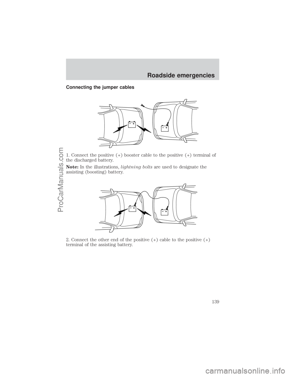
Connecting the jumper cables
1. Connect the positive (+) booster cable to the positive (+) terminal of
the discharged battery.
Note:In the illustrations,lightning boltsare used to designate the
assisting (boosting) battery.
2. Connect the other end of the positive (+) cable to the positive (+)
terminal of the assisting battery.
+–+–
+–+–
Roadside emergencies
139
ProCarManuals.com
Page 140 of 224
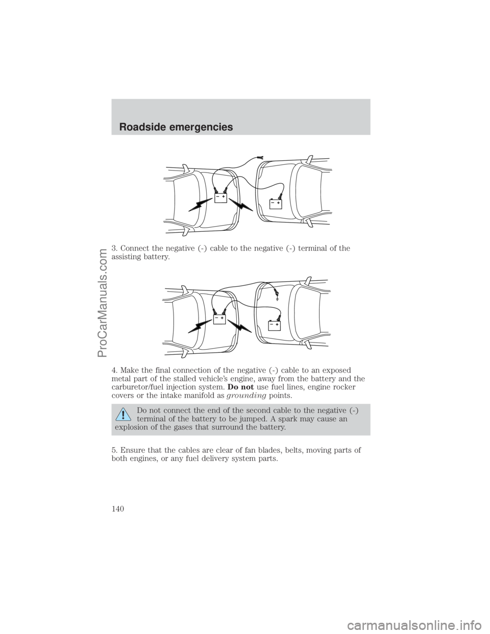
3. Connect the negative (-) cable to the negative (-) terminal of the
assisting battery.
4. Make the final connection of the negative (-) cable to an exposed
metal part of the stalled vehicle's engine, away from the battery and the
carburetor/fuel injection system.Do notuse fuel lines, engine rocker
covers or the intake manifold asgroundingpoints.
Do not connect the end of the second cable to the negative (-)
terminal of the battery to be jumped. A spark may cause an
explosion of the gases that surround the battery.
5. Ensure that the cables are clear of fan blades, belts, moving parts of
both engines, or any fuel delivery system parts.
+–+–
+–+–
Roadside emergencies
140
ProCarManuals.com