lights FORD E SERIES 2002 4.G User Guide
[x] Cancel search | Manufacturer: FORD, Model Year: 2002, Model line: E SERIES, Model: FORD E SERIES 2002 4.GPages: 272, PDF Size: 2.6 MB
Page 90 of 272
To install the new bulb:
Handle a halogen headlamp bulb carefully and keep out of
children's reach. Grasp the bulb only by its plastic base and do
not touch the glass. The oil from your hand could cause the bulb to
break the next time the headlamps are operated.
1. With the flat side of the bulb's plastic base facing upward, insert the
glass end of the bulb into the lamp assembly. You may need to turn the
bulb left or right to align the grooves in the plastic base with the tabs in
the lamp assembly. When the grooves are aligned, push the bulb into the
socket until the plastic base contacts the rear of the lamp assembly.
2. Install the bulb retaining ring over the plastic base until it contacts the
rear of the lamp assembly by rotating clockwise until you feel a ªstop.º
3. Install the electrical connector into the rear of the plastic base until it
snaps, locking it into position.
4. Install the headlamp assembly into the vehicle and secure it with the
clip tabs.
5. Turn the headlamps on and make sure they work properly. If the
headlamp was correctly aligned before you changed the bulb, you should
not need to align it again.
Replacing headlamp bulbs (low series)
To remove the headlamp bulb:
1. Make sure headlamp switch is in OFF position.
2. Open the hood.
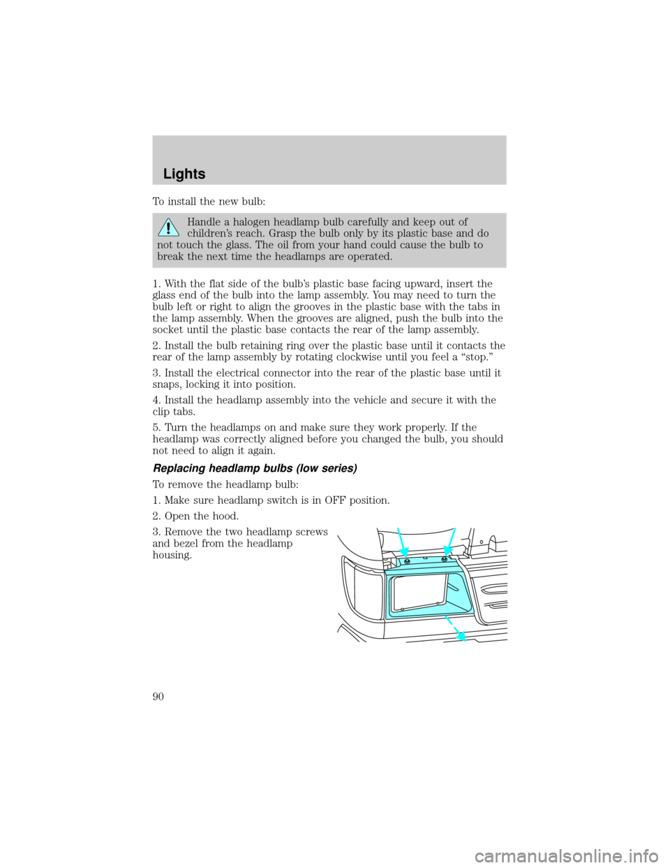
3. Remove the two headlamp screws
and bezel from the headlamp
housing.
Lights
90
Page 91 of 272
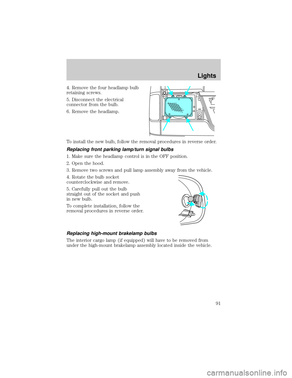
4. Remove the four headlamp bulb
retaining screws.
5. Disconnect the electrical
connector from the bulb.
6. Remove the headlamp.
To install the new bulb, follow the removal procedures in reverse order.
Replacing front parking lamp/turn signal bulbs
1. Make sure the headlamp control is in the OFF position.
2. Open the hood.
3. Remove two screws and pull lamp assembly away from the vehicle.
4. Rotate the bulb socket
counterclockwise and remove.
5. Carefully pull out the bulb
straight out of the socket and push
in new bulb.
To complete installation, follow the
removal procedures in reverse order.
Replacing high-mount brakelamp bulbs
The interior cargo lamp (if equipped) will have to be removed from
under the high-mount brakelamp assembly located inside the vehicle.
Lights
91
Page 92 of 272
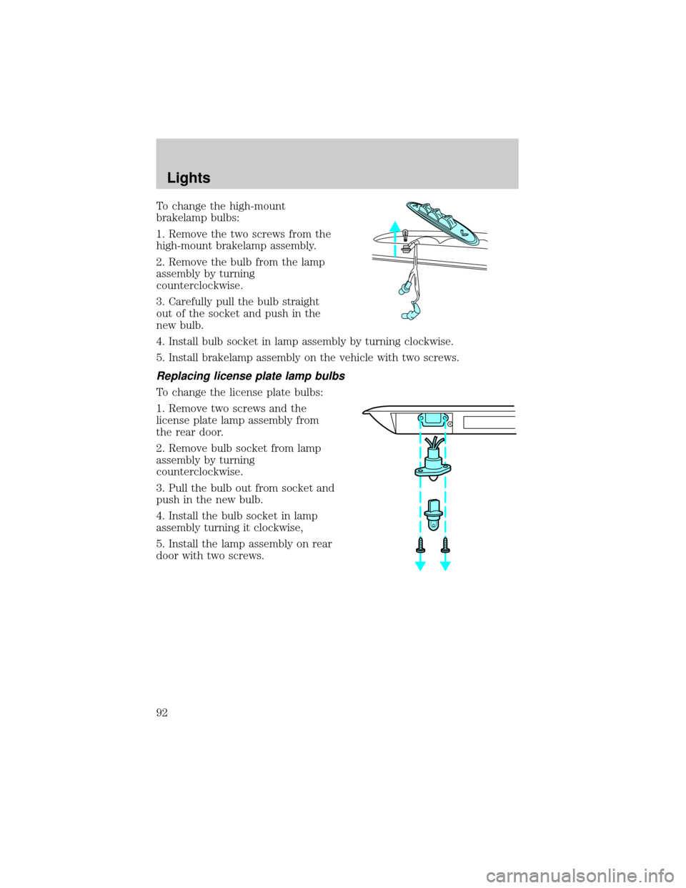
To change the high-mount
brakelamp bulbs:
1. Remove the two screws from the
high-mount brakelamp assembly.
2. Remove the bulb from the lamp
assembly by turning
counterclockwise.
3. Carefully pull the bulb straight
out of the socket and push in the
new bulb.
4. Install bulb socket in lamp assembly by turning clockwise.
5. Install brakelamp assembly on the vehicle with two screws.
Replacing license plate lamp bulbs
To change the license plate bulbs:
1. Remove two screws and the
license plate lamp assembly from
the rear door.
2. Remove bulb socket from lamp
assembly by turning
counterclockwise.
3. Pull the bulb out from socket and
push in the new bulb.
4. Install the bulb socket in lamp
assembly turning it clockwise,
5. Install the lamp assembly on rear
door with two screws.
Lights
92
Page 93 of 272
Replacing tail lamp/turn/backup lamp bulbs
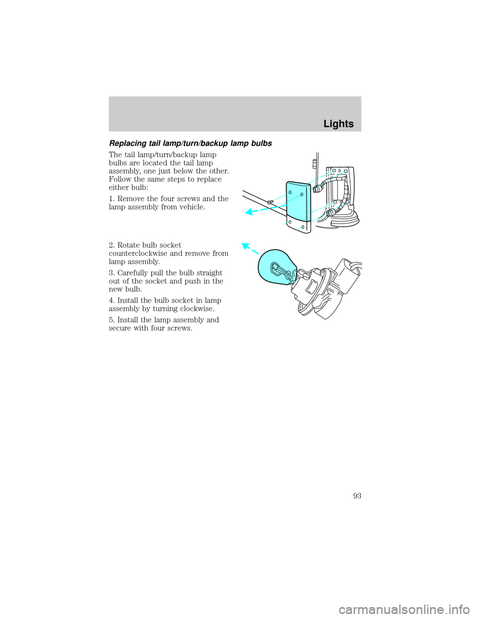
The tail lamp/turn/backup lamp
bulbs are located the tail lamp
assembly, one just below the other.
Follow the same steps to replace
either bulb:
1. Remove the four screws and the
lamp assembly from vehicle.
2. Rotate bulb socket
counterclockwise and remove from
lamp assembly.
3. Carefully pull the bulb straight
out of the socket and push in the
new bulb.
4. Install the bulb socket in lamp
assembly by turning clockwise.
5. Install the lamp assembly and
secure with four screws.
Lights
93
Page 112 of 272

Illuminated entry
The interior lamps illuminate when the remote entry system is used to
unlock the door(s) or sound the personal alarm.
The system automatically turns off after 25 seconds or when the ignition
is turned to the RUN or ACC position. The dome lamp control (if
equipped) mustnotbe set to the OFF position for the illuminated entry
system to operate.
The inside lights will not turn off if:
²they have been turned on with the dimmer control or
²any door is open
Locks and security
112
Page 148 of 272
STARTING
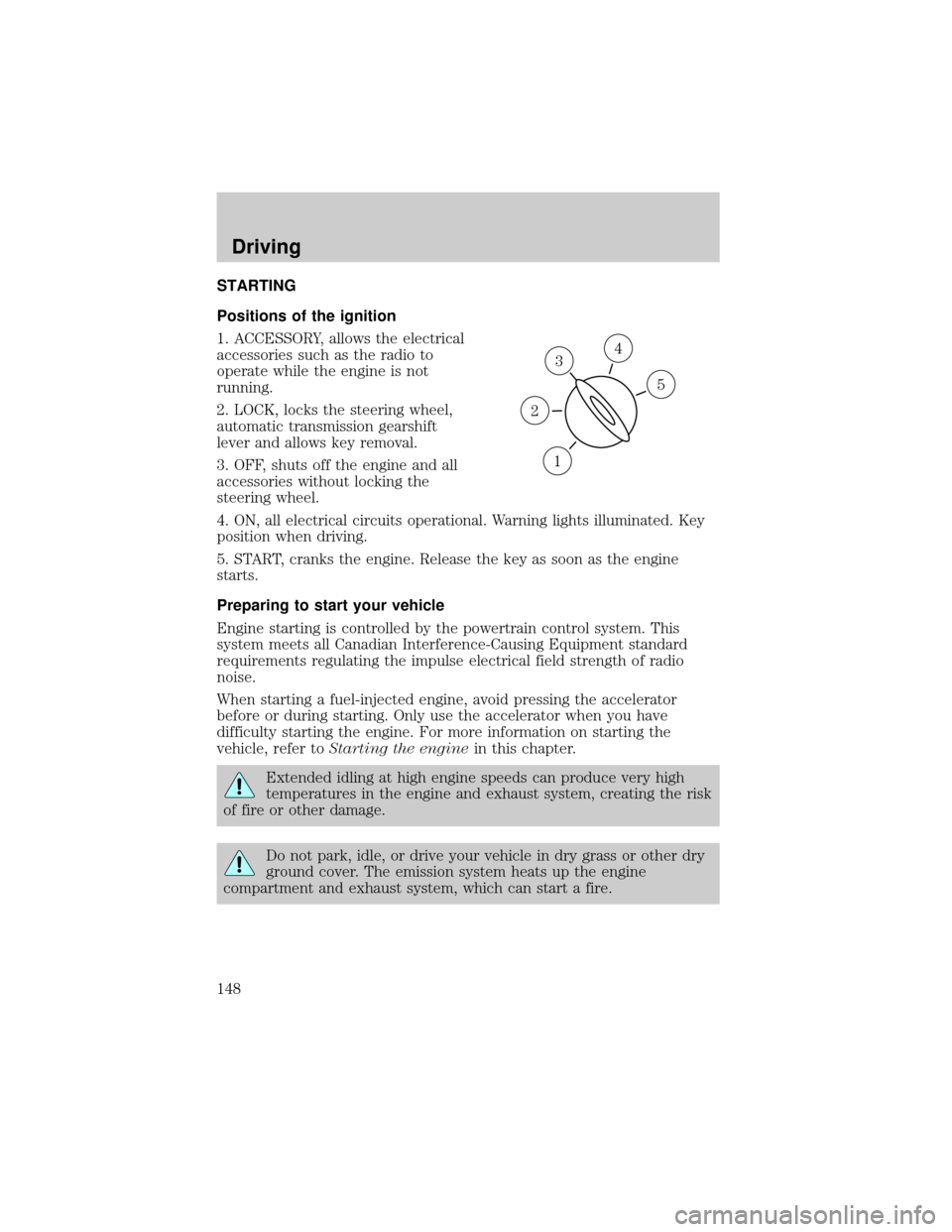
Positions of the ignition
1. ACCESSORY, allows the electrical
accessories such as the radio to
operate while the engine is not
running.
2. LOCK, locks the steering wheel,
automatic transmission gearshift
lever and allows key removal.
3. OFF, shuts off the engine and all
accessories without locking the
steering wheel.
4. ON, all electrical circuits operational. Warning lights illuminated. Key
position when driving.
5. START, cranks the engine. Release the key as soon as the engine
starts.
Preparing to start your vehicle
Engine starting is controlled by the powertrain control system. This
system meets all Canadian Interference-Causing Equipment standard
requirements regulating the impulse electrical field strength of radio
noise.
When starting a fuel-injected engine, avoid pressing the accelerator
before or during starting. Only use the accelerator when you have
difficulty starting the engine. For more information on starting the
vehicle, refer toStarting the enginein this chapter.
Extended idling at high engine speeds can produce very high
temperatures in the engine and exhaust system, creating the risk
of fire or other damage.
Do not park, idle, or drive your vehicle in dry grass or other dry
ground cover. The emission system heats up the engine
compartment and exhaust system, which can start a fire.
3
1
2
5
4
Driving
148
Page 150 of 272
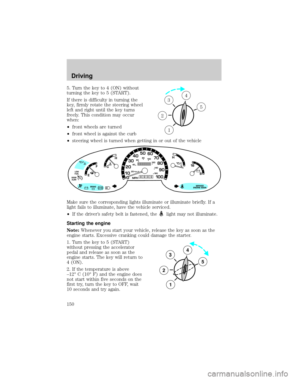
5. Turn the key to 4 (ON) without
turning the key to 5 (START).
If there is difficulty in turning the
key, firmly rotate the steering wheel
left and right until the key turns
freely. This condition may occur
when:
²front wheels are turned
²front wheel is against the curb
²steering wheel is turned when getting in or out of the vehicle
Make sure the corresponding lights illuminate or illuminate briefly. If a
light fails to illuminate, have the vehicle serviced.
²If the driver's safety belt is fastened, the
light may not illuminate.
Starting the engine
Note:Whenever you start your vehicle, release the key as soon as the
engine starts. Excessive cranking could damage the starter.
1. Turn the key to 5 (START)
without pressing the accelerator
pedal and release as soon as the
engine starts. The key will return to
4 (ON).
2. If the temperature is above
±12É C (10É F) and the engine does
not start within five seconds on the
first try, turn the key to OFF, wait
10 seconds and try again.
1
2
34
5
3
2
1
5
4
Driving
150
Page 174 of 272
If you need to arrange roadside assistance for yourself, Ford Motor
Company will reimburse a reasonable amount. To obtain reimbursement
information, U.S. Ford or Mercury vehicles customers call
1-800-241-3673; Lincoln vehicle customers call 1±800±521±4140.
Canadian customers who need to obtain reimbursement information, call
1±800±665±2006.
ROADSIDE COVERAGE BEYOND BASIC WARRANTY
In the United States, you may purchase additional roadside assistance
coverage beyond this period through the Ford Auto Club by contacting
your Ford or Lincoln Mercury dealer.
Similarly in Canada, for uninterrupted Roadside Assistance coverage, you
may purchase extended coverage prior to your Basic Warranty's Roadside
Assistance expiring. For more information and enrollment, contact
1±877±294±2582 or visit our website at www.ford.ca.
HAZARD FLASHER
Use only in an emergency to warn traffic of vehicle breakdown,
approaching danger, etc. The hazard flashers can be operated when the
ignition is off.
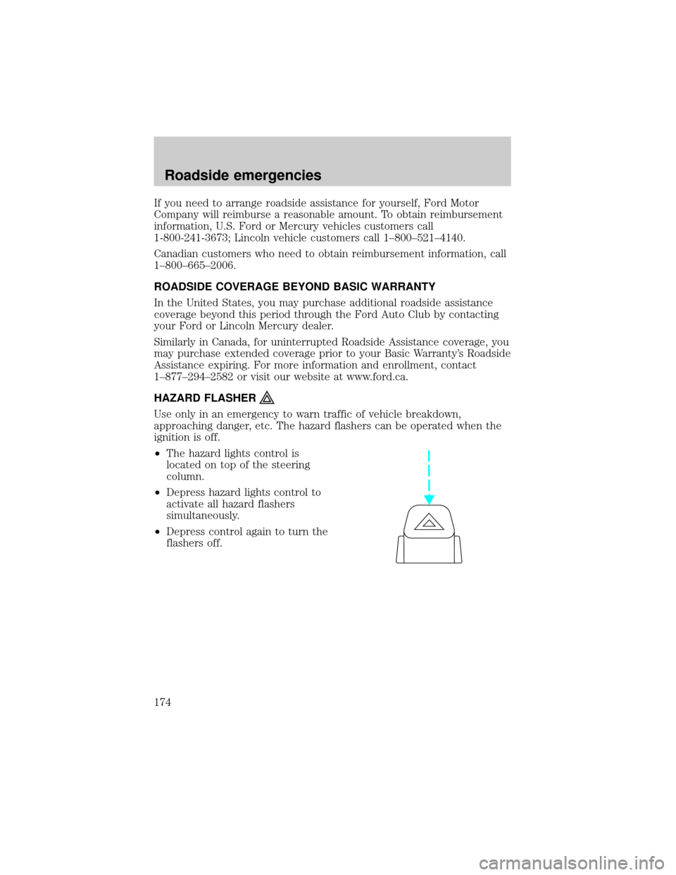
²The hazard lights control is
located on top of the steering
column.
²Depress hazard lights control to
activate all hazard flashers
simultaneously.
²Depress control again to turn the
flashers off.
Roadside emergencies
174
Page 183 of 272
Fuse/Relay
LocationFuse Amp
RatingPower Distribution Box
Description
12 60A** Engine Compartment Fuses 25,
27
13 50A** Blower Motor Relay (Blower
Motor)
14 30A** Trailer Running Lamps Relay,
Trailer Backup Lamps Relay
15 40A** Main Light Switch, Daytime
Running Lights (DRL)
16 50A** Auxiliary Blower Motor Relay
17 30A** Fuel Pump Relay
18 60A** I/P Fuses 40, 41,26, 33, 39
19 60A** 4WABS Module
20 20A** Electric Brake Controller
21 50A** Modified Vehicle Power
22 40A** Trailer Battery Charge Relay,
Modified Vehicles
23 60A** Ignition Switch, Fuse Panel
24 20A* Natural Gas Tank Valves (NGV
only)
25 20A* NGV Module (Natural Gas Only)
26 10A* A/C Clutch (4.2L Only)
27 15A* DRL Module, Horn Relay
28 Ð PCM Diode
29 Ð Not Used
A Ð Not Used
B Ð Stop Lamp Relay
C Ð Trailer Backup Lamps Relay
D Ð Trailer Running Lamps Relay
E Ð Trailer Battery Charge Relay
F Ð IDM Relay (Diesel Only), A/C
Clutch Relay (4.2L Only)
G Ð PCM Relay
Roadside emergencies
183
Page 242 of 272
If other than Ford, Motorcraft or Ford-authorized parts are used for
maintenance replacements or for service of components affecting
emission control, such non-Ford parts should be equivalent to genuine
Ford Motor Company parts in performance and durability.
Do not park, idle, or drive your vehicle in dry grass or other dry
ground cover. The emission system heats up the engine
compartment and exhaust system, which can start a fire.
Illumination of the ªService Engine Soonº light, charging system warning
light or the temperature warning light, fluid leaks, strange odors, smoke
or loss of engine power, could indicate that the emission control system
is not working properly.
Exhaust leaks may result in entry of harmful and potentially
lethal fumes into the passenger compartment.
Do not make any unauthorized changes to your vehicle or engine. By
law, vehicle owners and anyone who manufactures, repairs, services,
sells, leases, trades vehicles, or supervises a fleet of vehicles are not
permitted to intentionally remove an emission control device or prevent
it from working. Information about your vehicle's emission system is on
the Vehicle Emission Control Information Decal located on or near the
engine. This decal identifies engine displacement and gives some tune up
specifications.
Please consult yourWarranty Guidefor complete emission warranty
information.
Readiness for Inspection/Maintenance (I/M) testing
In some localities, it may be a legal requirement to pass an I/M test of
the on-board diagnostics system. If your ªCheck Engine/Service Engine
Soonº light is on, refer to the description in theWarning lights and
chimessection of theInstrument Clusterchapter. Your vehicle may not
pass the I/M test with the ªCheck Engine/Service Engine Soonº light on.
If the vehicle's powertrain system or its battery has just been serviced,
the on-board diagnostics system is reset to a ªnot ready for I/M testº
condition. To ready the on-board diagnostics system for I/M testing, a
minimum of 30 minutes of city and highway driving is necessary as
described below:
²First, at least 10 minutes of driving on an expressway or highway.
Maintenance and specifications
242