ECU FORD E SERIES 2022 User Guide
[x] Cancel search | Manufacturer: FORD, Model Year: 2022, Model line: E SERIES, Model: FORD E SERIES 2022Pages: 300, PDF Size: 3.18 MB
Page 51 of 300
PASSIVE ANTI-THEFT
SYSTEM
Note:
The system is not compatible with
non-Ford aftermarket remote start systems.
Use of these systems could result in engine
starting problems and a loss of security
protection.
Note: Prevent these objects from touching
the coded key when starting your vehicle.
Metallic objects, electronic devices or a
second coded key on the same key chain
could result in vehicle starting problems,
especially if they are too close to the key
when starting your vehicle. Switch the
ignition off, move all objects on the key
chain away from the coded key and restart
your vehicle if a problem occurs.
Note: Do not leave a duplicate coded key
in your vehicle. Always take your keys and
lock all doors when leaving your vehicle.
SecuriLock®
The system helps prevent the engine from
starting unless you use a coded key
programmed to your vehicle. Using the
wrong key may prevent your vehicle from
starting. A message may appear in the
information display.
If you are unable to start your vehicle with
a coded key, it is not operating correctly.
A message may appear in the information
display.
Automatic Arming
The system arms when you switch the
ignition off.
Automatic Disarming
The system disarms when you switch the
ignition on with a coded key. Replacement Keys
Your vehicle may have two integrated
keyhead transmitters.
The integrated keyhead transmitter
functions as a programmed ignition key
that starts your vehicle.
If your programmed transmitters or
standard SecuriLock coded keys become
lost or stolen and you do not have an extra
coded key, you need to have your vehicle
towed to an authorized dealer. You need
to erase the key codes from your vehicle
and program new coded keys.
Store an extra programmed key away from
your vehicle in a safe place. To purchase
additional spare or replacement keys,
contact an authorized dealer.
If you have a spare key, you need to
program it. See Replacing a Lost Key or
Remote Control (page 44).
48
E-Series (TE4) Canada/United States of America, enUSA, Edition date: 202010, First-Printing Security
Page 81 of 300
The front row outboard non-adjustable
head restraints consist of a trimmed foam
covering over the upper structure of the
seatback. Properly adjust the seatback to
an upright driving or riding position, so that
the head restraint is positioned as close as
possible to the back of your head.
MANUAL SEATS (IF EQUIPPED)
WARNING: Make sure the seat fully
locks into place by rocking it backward
and forward. Not securing the seat into
the locked position can be dangerous in
a crash and could cause serious personal
injury or death.
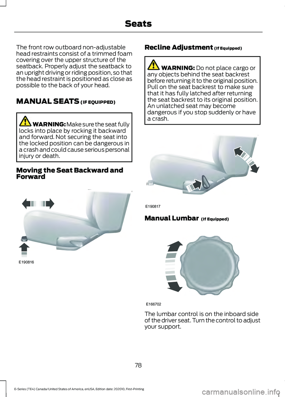
Moving the Seat Backward and
Forward Recline Adjustment
(If Equipped)
WARNING:
Do not place cargo or
any objects behind the seat backrest
before returning it to the original position.
Pull on the seat backrest to make sure
that it has fully latched after returning
the seat backrest to its original position.
An unlatched seat may become
dangerous if you stop suddenly or have
a crash. Manual Lumbar
(If Equipped)
The lumbar control is on the inboard side
of the driver seat. Turn the control to adjust
your support.
78
E-Series (TE4) Canada/United States of America, enUSA, Edition date: 202010, First-Printing SeatsE190816 E190817 E166702
Page 99 of 300
AUTOMATIC TRANSMISSION
WARNING: Apply the parking
brake, shift into park (P), switch the
ignition off and remove the key before
you leave your vehicle. Failure to follow
this instruction could result in personal
injury or death. Putting your vehicle in or out of
gear:
1. Fully press down the brake pedal.
2. Move the gearshift lever into the
preferred gear.
3. When you finish driving, come to a complete stop.
4. Move the gearshift lever and securely latch it in park (P).
5. Release the brake pedal and the transmission remains in the selected
gear.
Park (P)
This position locks the transmission and
prevents the wheels from turning.
Reverse (R)
With the transmission in reverse (R), your
vehicle moves backward. Always come to
a complete stop before shifting into and
out of reverse (R). Neutral (N)
With the transmission in neutral (N), you
can start your vehicle and it is free to roll.
Hold the brake pedal down when in this
position.
Drive (D)
Drive (D) is the normal driving position for
the best fuel economy. The overdrive
function allows automatic upshifts and
downshifts through gears one through six.
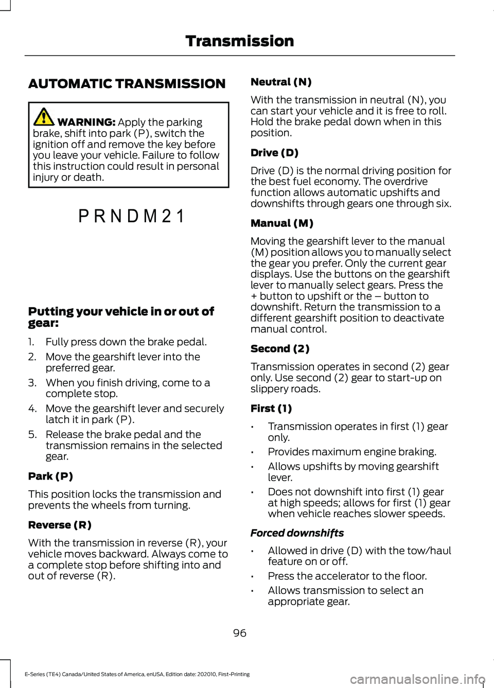
Manual (M)
Moving the gearshift lever to the manual
(M) position allows you to manually select
the gear you prefer. Only the current gear
displays. Use the buttons on the gearshift
lever to manually select gears. Press the
+ button to upshift or the – button to
downshift. Return the transmission to a
different gearshift position to deactivate
manual control.
Second (2)
Transmission operates in second (2) gear
only. Use second (2) gear to start-up on
slippery roads.
First (1)
•
Transmission operates in first (1) gear
only.
• Provides maximum engine braking.
• Allows upshifts by moving gearshift
lever.
• Does not downshift into first (1) gear
at high speeds; allows for first (1) gear
when vehicle reaches slower speeds.
Forced downshifts
• Allowed in drive (D) with the tow/haul
feature on or off.
• Press the accelerator to the floor.
• Allows transmission to select an
appropriate gear.
96
E-Series (TE4) Canada/United States of America, enUSA, Edition date: 202010, First-Printing TransmissionP R N D M 2 1E307627
Page 102 of 300
If the fuse is not blown and the brake
lamps are working properly, the following
procedure allows you to move the gearshift
lever from park (P):
1. Apply the parking brake. Switch the
ignition key to 1 (off), then remove the
key.
2. Move the steering column to the full down and full rearward position,
toward the driver seat.
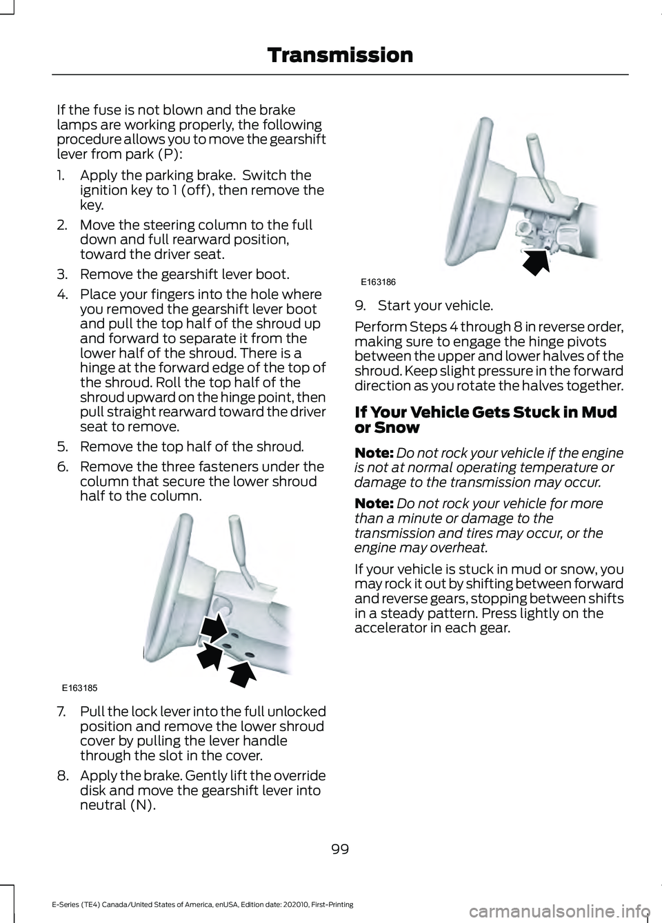
3. Remove the gearshift lever boot.
4. Place your fingers into the hole where you removed the gearshift lever boot
and pull the top half of the shroud up
and forward to separate it from the
lower half of the shroud. There is a
hinge at the forward edge of the top of
the shroud. Roll the top half of the
shroud upward on the hinge point, then
pull straight rearward toward the driver
seat to remove.
5. Remove the top half of the shroud.
6. Remove the three fasteners under the column that secure the lower shroud
half to the column. 7.
Pull the lock lever into the full unlocked
position and remove the lower shroud
cover by pulling the lever handle
through the slot in the cover.
8. Apply the brake. Gently lift the override
disk and move the gearshift lever into
neutral (N). 9. Start your vehicle.
Perform Steps 4 through 8 in reverse order,
making sure to engage the hinge pivots
between the upper and lower halves of the
shroud. Keep slight pressure in the forward
direction as you rotate the halves together.
If Your Vehicle Gets Stuck in Mud
or Snow
Note:
Do not rock your vehicle if the engine
is not at normal operating temperature or
damage to the transmission may occur.
Note: Do not rock your vehicle for more
than a minute or damage to the
transmission and tires may occur, or the
engine may overheat.
If your vehicle is stuck in mud or snow, you
may rock it out by shifting between forward
and reverse gears, stopping between shifts
in a steady pattern. Press lightly on the
accelerator in each gear.
99
E-Series (TE4) Canada/United States of America, enUSA, Edition date: 202010, First-Printing TransmissionE163185 E163186
Page 138 of 300

1. Park the loaded vehicle, without the
trailer, on a level surface.
2. Measure the height to the top of your vehicle's front wheel opening on the
fender. This is H1.
3. Attach the loaded trailer to your vehicle
without the weight-distributing bars
connected.
4. Measure the height to the top of your vehicle's front wheel opening on the
fender a second time. This is H2.
5. Install and adjust the tension in the weight-distributing bars so that the
height of your vehicle's front wheel
opening on the fender is approximately
half the way down from H2, toward H1.
6. Check that the trailer is level or slightly
nose down toward your vehicle. If not,
adjust the ball height accordingly and
repeat Steps 2-6.
When the trailer is level or slightly nose
down toward the vehicle:
• Lock the bar tension adjuster in place.
• Check that the trailer tongue securely
attaches and locks onto the hitch.
• Install safety chains, lighting, and trailer
brake controls as required by law or the
trailer manufacturer.
Safety Chains
Note: Do not attach safety chains to the
bumper.
Always connect the safety chains to the
frame or hook retainers of your vehicle
hitch.
To connect the safety chains, cross the
chains under the trailer tongue and allow
enough slack for turning tight corners. Do
not allow the chains to drag on the ground. Trailer Brakes WARNING: Do not connect a
trailer's hydraulic brake system directly
to your vehicle's brake system. Your
vehicle may not have enough braking
power and your chances of having a
collision greatly increase.
Electric brakes and manual, automatic or
surge-type trailer brakes are safe if you
install them properly and adjust them to
the manufacturer's specifications. The
trailer brakes must meet local and federal
regulations.
The rating for the tow vehicle's braking
system operation is at the gross vehicle
weight rating, not the gross combined
weight rating.
Separate functioning brake systems
are required for safe control of towed
vehicles and trailers weighing more
than 1500 lb (680 kg) when loaded.
Integrated Trailer Brake Controller (If
Equipped) WARNING:
Use the integrated
trailer brake controller to properly adjust
the trailer brakes and check all
connections before towing a trailer.
Failure to follow this instruction could
result in the loss of control of your
vehicle, personal injury or death.
Note: The Ford trailer brake controller has
been verified to be compatible with trailers
having electric-actuated drum brakes (one
to four axles) and electric-over-hydraulic
brakes. It will not activate hydraulic
surge-style trailer brakes. It is the
responsibility of the customer to ensure that
the trailer brakes are adjusted appropriately,
functioning normally and all electric
connections are properly made.
135
E-Series (TE4) Canada/United States of America, enUSA, Edition date: 202010, First-Printing Towing
Page 146 of 300
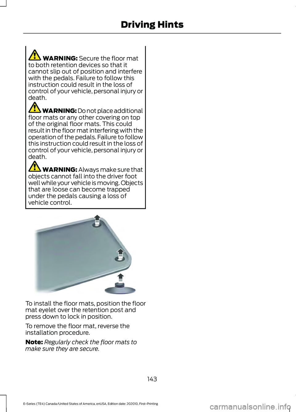
WARNING: Secure the floor mat
to both retention devices so that it
cannot slip out of position and interfere
with the pedals. Failure to follow this
instruction could result in the loss of
control of your vehicle, personal injury or
death. WARNING: Do not place additional
floor mats or any other covering on top
of the original floor mats. This could
result in the floor mat interfering with the
operation of the pedals. Failure to follow
this instruction could result in the loss of
control of your vehicle, personal injury or
death. WARNING:
Always make sure that
objects cannot fall into the driver foot
well while your vehicle is moving. Objects
that are loose can become trapped
under the pedals causing a loss of
vehicle control. To install the floor mats, position the floor
mat eyelet over the retention post and
press down to lock in position.
To remove the floor mat, reverse the
installation procedure.
Note:
Regularly check the floor mats to
make sure they are secure.
143
E-Series (TE4) Canada/United States of America, enUSA, Edition date: 202010, First-Printing Driving HintsE142666
Page 153 of 300
Additional Assistance
If you have questions or concerns, or are
unsatisfied with the service you are
receiving, follow these steps:
1. Contact your Sales Representative or
Service Advisor at your selling or
servicing authorized dealer.
2. If your inquiry or concern remains unresolved, contact the Sales Manager,
Service Manager or Customer Relations
Manager.
3. If you require assistance or clarification
on Ford Motor Company policies,
please contact the Ford Customer
Relationship Center.
In order to help us serve you better, please
have the following information available
when contacting a Customer Relationship
Center:
• Vehicle Identification Number.
• Your telephone number (home and
business).
• The name of the authorized dealer and
city where located.
• The vehicle ’s current odometer reading.
In some states within the United States,
you must directly notify Ford in writing
before pursuing remedies under your
state's warranty laws, and Ford is also
allowed a final repair attempt.
Additionally, in some states within the
United States, a consumer has the option
of submitting a warranty dispute to the
BBB Auto Line before taking action under
the Magnuson-Moss Warranty Act, or to
the extent allowed by state law, before
pursuing replacement or repurchase
remedies provided by certain state laws.
This dispute handling procedure is not
required prior to enforcing state created
rights or other rights which are independent
of the Magnuson-Moss Warranty Act or
state replacement or repurchase laws. IN CALIFORNIA (U.S. ONLY)
California Civil Code Section 1793.2(d)
requires that, if a manufacturer or its
representative is unable to repair a motor
vehicle to conform to the vehicle
’s
applicable express warranty after a
reasonable number of attempts, the
manufacturer shall be required to either
replace the vehicle with one substantially
identical or repurchase the vehicle and
reimburse the buyer in an amount equal to
the actual price paid or payable by the
consumer (less a reasonable allowance
for consumer use). The consumer has the
right to choose whether to receive a refund
or replacement vehicle.
California Civil Code Section 1793.22(b)
presumes that the manufacturer has had
a reasonable number of attempts to
conform the vehicle to its applicable
express warranties if, within the first 18
months of ownership of a new vehicle or
the first 18,000 mi (29,000 km), whichever
occurs first:
1. Two or more repair attempts are made
on the same non-conformity likely to
cause death or serious bodily injury OR
2. Four or more repair attempts are made
on the same nonconformity (a defect
or condition that substantially impairs
the use, value or safety of the vehicle)
OR
3. The vehicle is out of service for repair of nonconformities for a total of more
than 30 calendar days (not necessarily
all at one time).
In the case of 1 or 2 above, the consumer
must also notify the manufacturer of the
need for the repair of the nonconformity
at the following address:
Ford Motor Company
16800 Executive Plaza Drive
Mail Drop 3NE-B
Dearborn, MI 48126
150
E-Series (TE4) Canada/United States of America, enUSA, Edition date: 202010, First-Printing Customer Assistance
Page 157 of 300
If NHTSA receives similar
complaints, it may open an
investigation, and if it finds that a
safety defect exists in a group of
vehicles, it may order a recall and
remedy campaign. However,
NHTSA cannot become involved
in individual problems between
you, your dealer, or Ford Motor
Company.
To contact NHTSA, you may call
the Vehicle Safety Hotline
toll-free at 1-888-327-4236 (TTY:
1-800-424-9153); go to
www
.s a f er c ar .g o v ; or write to:
Administrator 1200 New Jersey Avenue,
Southeast
Washington, D.C. 20590
You can also obtain other
information about motor vehicle
safety from www .s a f er c ar .g o v .
REPORTING SAFETY DEFECTS
(CANADA ONLY)
If you believe that your vehicle has a defect
which could cause a crash or could cause
injury or death, you should immediately
inform Transport Canada and Ford of
Canada. Transport Canada Contact Information
http://www.tc.gc.ca/eng/motorvehiclesafety/reporting-defects-motor-
vehicles.html (English)
Website
http://www.tc.gc.ca/fra/securiteautomobile/signaler-defauts-vehicules-
automobiles.html (French)
Website
1-800-333-0510
Phone Ford of Canada Contact Information
www.ford.ca
Website
1-800-565-3673
Phone
154
E-Series (TE4) Canada/United States of America, enUSA, Edition date: 202010, First-Printing Customer Assistance
Page 168 of 300
GENERAL INFORMATION
Have your vehicle serviced regularly to help
maintain its roadworthiness and resale
value. There is a large network of
authorized dealers that are there to help
you with their professional servicing
expertise. We believe that their specially
trained technicians are best qualified to
service your vehicle properly and expertly.
They are supported by a wide range of
highly specialized tools developed
specifically for servicing your vehicle.
If your vehicle requires professional service,
an authorized dealer can provide the
necessary parts and service. Check your
warranty information to find out which
parts and services are covered.
Use only recommended fuels, lubricants,
fluids and service parts conforming to
specifications. Motorcraft® parts are
designed and built to provide the best
performance in your vehicle.
Precautions
•
Do not work on a hot engine.
• Make sure that nothing gets caught in
moving parts.
• Do not work on a vehicle with the
engine running in an enclosed space,
unless you are sure you have enough
ventilation.
• Keep all open flames and other burning
material (such as cigarettes) away
from the battery and all fuel related
parts.
Working with the Engine Off
1. Set the parking brake and shift the transmission to park (P). 2. Switch off the engine.
3. Block the wheels.
Working with the Engine On WARNING: To reduce the risk of
vehicle damage and personal burn
injuries, do not start your engine with the
air cleaner removed and do not remove
it while the engine is running.
1. Set the parking brake and shift the transmission to park (P).
2. Block the wheels.
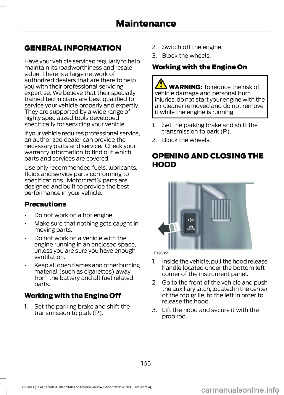
OPENING AND CLOSING THE
HOOD 1.
Inside the vehicle, pull the hood release
handle located under the bottom left
corner of the instrument panel.
2. Go to the front of the vehicle and push
the auxiliary latch, located in the center
of the top grille, to the left in order to
release the hood.
3. Lift the hood and secure it with the prop rod.
165
E-Series (TE4) Canada/United States of America, enUSA, Edition date: 202010, First-Printing MaintenanceE196351
Page 172 of 300
Note:
Failure to use the correct air filter
element may result in severe engine
damage. The customer warranty may be
void for any damage to the engine if the
correct air filter element is not used.
When changing the air filter element, use
only the air filter element listed. See
Motorcraft Parts (page 223). The air filter
element should be replaced at the
appropriate intervals. See Normal
Scheduled Maintenance (page 254).
Note: Failure to use the correct air filter
element may result in severe engine
damage. Resulting component damage
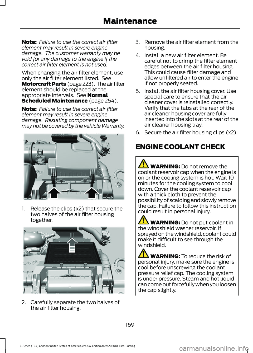
may not be covered by the vehicle Warranty. 1. Release the clips (x2) that secure the
two halves of the air filter housing
together. 2. Carefully separate the two halves of
the air filter housing. 3.
Remove the air filter element from the
housing.
4. Install a new air filter element. Be careful not to crimp the filter element
edges between the air filter housing.
This could cause filter damage and
allow unfiltered air to enter the engine
if not properly seated.
5. Install the air filter housing cover. Use special care to ensure that the air
cleaner cover is reinstalled correctly.
Verify that the tabs at the rear of the
air cleaner housing cover are fully
inserted into the slots at the rear of the
air cleaner housing tray.
6. Secure the air filter housing clips (x2).
ENGINE COOLANT CHECK WARNING:
Do not remove the
coolant reservoir cap when the engine is
on or the cooling system is hot. Wait 10
minutes for the cooling system to cool
down. Cover the coolant reservoir cap
with a thick cloth to prevent the
possibility of scalding and slowly remove
the cap. Failure to follow this instruction
could result in personal injury. WARNING:
Do not put coolant in
the windshield washer reservoir. If
sprayed on the windshield, coolant could
make it difficult to see through the
windshield. WARNING:
To reduce the risk of
personal injury, make sure the engine is
cool before unscrewing the coolant
pressure relief cap. The cooling system
is under pressure. Steam and hot liquid
can come out forcefully when you loosen
the cap slightly.
169
E-Series (TE4) Canada/United States of America, enUSA, Edition date: 202010, First-Printing MaintenanceE310547 E310548