headlamp FORD ESCAPE 2004 1.G User Guide
[x] Cancel search | Manufacturer: FORD, Model Year: 2004, Model line: ESCAPE, Model: FORD ESCAPE 2004 1.GPages: 240, PDF Size: 2.5 MB
Page 41 of 240
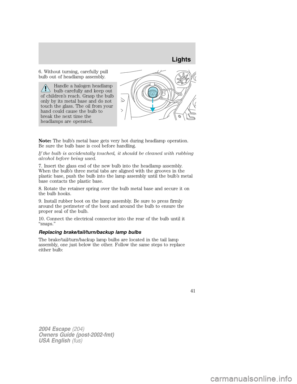
6. Without turning, carefully pull
bulb out of headlamp assembly.
Handle a halogen headlamp
bulb carefully and keep out
of children’s reach. Grasp the bulb
only by its metal base and do not
touch the glass. The oil from your
hand could cause the bulb to
break the next time the
headlamps are operated.
Note:The bulb’s metal base gets very hot during headlamp operation.
Be sure the bulb base is cool before handling.
If the bulb is accidentally touched, it should be cleaned with rubbing
alcohol before being used.
7. Insert the glass end of the new bulb into the headlamp assembly.
When the bulb’s three metal tabs are aligned with the grooves in the
plastic base, push the bulb into the lamp assembly until the bulb’s metal
base contacts the plastic base.
8. Rotate the retainer spring over the bulb metal base and secure it on
the bulb hooks.
9. Install rubber boot on the lamp assembly. Be sure to press firmly
around the perimeter of the boot and around the bulb to ensure the
proper seal of the bulb.
10. Connect the electrical connector into the rear of the bulb until it
“snaps.”
Replacing brake/tail/turn/backup lamp bulbs
The brake/tail/turn/backup lamp bulbs are located in the tail lamp
assembly, one just below the other. Follow the same steps to replace
either bulb:
2004 Escape(204)
Owners Guide (post-2002-fmt)
USA English(fus)
Lights
41
Page 42 of 240
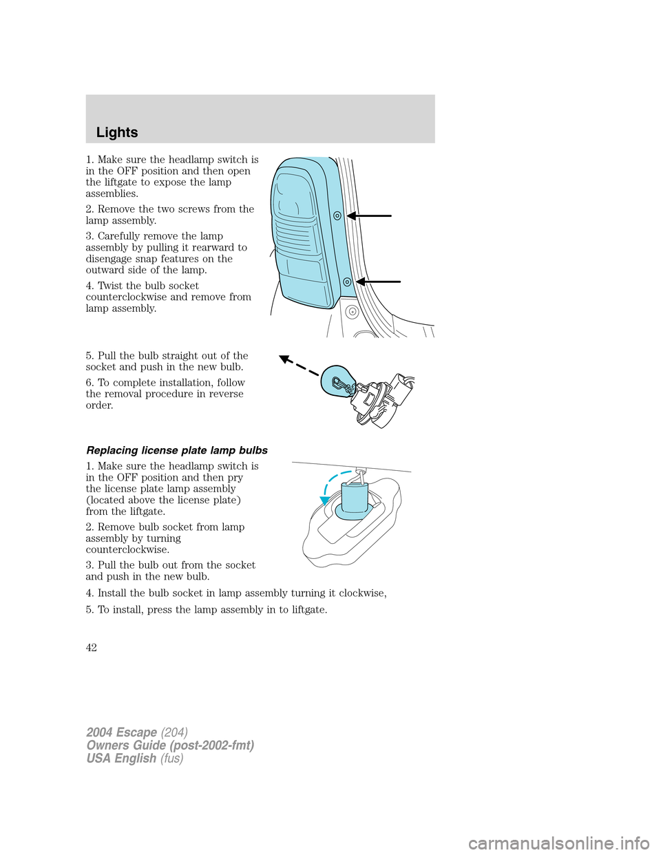
1. Make sure the headlamp switch is
in the OFF position and then open
the liftgate to expose the lamp
assemblies.
2. Remove the two screws from the
lamp assembly.
3. Carefully remove the lamp
assembly by pulling it rearward to
disengage snap features on the
outward side of the lamp.
4. Twist the bulb socket
counterclockwise and remove from
lamp assembly.
5. Pull the bulb straight out of the
socket and push in the new bulb.
6. To complete installation, follow
the removal procedure in reverse
order.
Replacing license plate lamp bulbs
1. Make sure the headlamp switch is
in the OFF position and then pry
the license plate lamp assembly
(located above the license plate)
from the liftgate.
2. Remove bulb socket from lamp
assembly by turning
counterclockwise.
3. Pull the bulb out from the socket
and push in the new bulb.
4. Install the bulb socket in lamp assembly turning it clockwise,
5. To install, press the lamp assembly in to liftgate.
2004 Escape(204)
Owners Guide (post-2002-fmt)
USA English(fus)
Lights
42
Page 48 of 240
•Install the transmitter (6) on to storage compartment door (3)
aligning the actuator control (8) with the rubber plunger (1). Close
the storage compartment door (3) to verify proper fit. Do not force
the storage compartment door (3) or you may break the door latch. If
the rubber actuator (1) is the proper length the storage compartment
door will close. Press the storage compartment door (3) to activate
the transmitter (6).
Illuminated visor mirror (if equipped)
Lift the mirror cover to turn on the
visor mirror lamps.
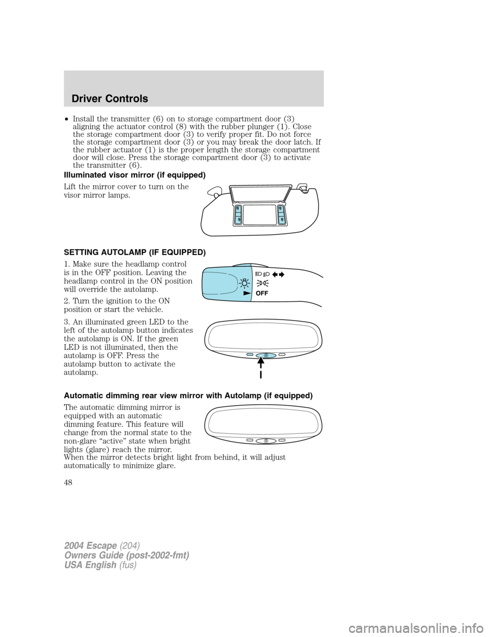
SETTING AUTOLAMP (IF EQUIPPED)
1. Make sure the headlamp control
is in the OFF position. Leaving the
headlamp control in the ON position
will override the autolamp.
2. Turn the ignition to the ON
position or start the vehicle.
3. An illuminated green LED to the
left of the autolamp button indicates
the autolamp is ON. If the green
LED is not illuminated, then the
autolamp is OFF. Press the
autolamp button to activate the
autolamp.
Automatic dimming rear view mirror with Autolamp (if equipped)
The automatic dimming mirror is
equipped with an automatic
dimming feature. This feature will
change from the normal state to the
non-glare “active” state when bright
lights (glare) reach the mirror.
When the mirror detects bright light from behind, it will adjust
automatically to minimize glare.
2004 Escape(204)
Owners Guide (post-2002-fmt)
USA English(fus)
Driver Controls
48
Page 73 of 240
5. Turn the ignition from the 1 (OFF) position to the 3 (ON) position.
Keep the ignition in the 3 (ON) position for at least three seconds, but
no more than 10 seconds.
6. Turn the ignition to the 1 (OFF) position and remove the second
previously programmedcoded keyfrom the ignition.
7. Within twenty seconds turning the ignition to the 1 (OFF) position
and removing the previously programmedcoded key,insert the new
unprogrammed key (new key/valet key) into the ignition.
8. Turn the ignition from the 1 (OFF) position to the 3 (ON) position.
Keep the ignition in the 3 (ON) position for at least three seconds but
not more than 10 seconds.
9. Remove the newly programmedcoded keyfrom the ignition.
If the key has been successfully programmed it will start the vehicle’s
engine and the theft indicator light will illuminate for three seconds and
then go out.
If the key was not successfully programmed, it will not start your
vehicle’s engine and the theft indicator light will flash on and off, and
you may repeat Steps 1 through 5. If failure repeats, bring your vehicle
to your dealer to have the new key(s) programmed.
To program additional new unprogrammed key(s), wait twenty seconds
and then repeat this procedure from Step 1.
PERIMETER ALARM SYSTEM (IF EQUIPPED)
The perimeter anti-theft system will warn you in the event of an
unauthorized entry to your vehicle.
If there is any potential perimeter anti-theft problem with your vehicle,
ensureALL remote entry transmittersare taken to the dealership to
aid in troubleshooting.
Arming the system
When armed, this system will respond if unauthorized entry is
attempted. When unauthorized entry occurs, the system will flash the
headlamps and parking lamps, and will sound the horn.
The system is ready to arm whenever key is removed from the ignition.
Either of the following actions will prearm the alarm system:
•Press the
control on the remote entry transmitter.
•Lock the doors with the key in the key cylinder.
•Open a door and press the power door lock control to lock all the
doors, and then close the door.
2004 Escape(204)
Owners Guide (post-2002-fmt)
USA English(fus)
Locks and Security
73
Page 95 of 240
•the driver’s safety belt is unbuckled
•the parklamps/headlamps are in OFF position (If vehicle is equipped
with Autolamps, this will not affect the procedure.)
To reduce the risk of injury, do not deactivate/activate the Belt
Minder feature while driving the vehicle.
1. Turn the ignition switch to the RUN (or ON) position. (DO NOT
START THE ENGINE)
2. Wait until the safety belt warning light turns off. (Approximately 1–2
minutes)
•Steps 3–5 must be completed within 60 seconds or the procedure will
have to be repeated.
3. Uncoil then retract the safety belt three times, ending with the safety
belt retracted. This can be done before or during BeltMinder warning
activation.
4. Turn on the parklamps/headlamps, turn off the parklamps/headlamps.
5. Uncoil then retract the safety belt three times, ending with the safety
belt retracted.
•After step 5 the safety belt warning light will be turned on for three
seconds.
6. Within seven seconds of the safety belt warning light turning off,
uncoil then retract the safety belt.
•This will disable BeltMinder if it is currently enabled, or enable
BeltMinder if it is currently disabled.
7. Confirmation of disabling BeltMinder is provided by flashing the safety
belt warning light four times per second for three seconds.
8. Confirmation of enabling BeltMinder is provided by flashing the safety
belt warning light four times per second for three seconds, followed by
three seconds with the safety belt warning light off, then followed by
flashing the safety belt warning light four times per second for three
seconds again.
9. After receiving confirmation, the deactivation/activation procedure is
complete.
2004 Escape(204)
Owners Guide (post-2002-fmt)
USA English(fus)
Seating and Safety Restraints
95
Page 116 of 240
If you smell exhaust fumes inside your vehicle, have your dealer
inspect your vehicle immediately. Do not drive if you smell
exhaust fumes.
Important safety precautions
When the engine starts, the idle RPM runs faster to warm the engine. If
the engine idle speed does not slow down automatically, have the vehicle
checked.
Before starting the vehicle:
1. Make sure all vehicle occupants buckle their safety belts. For more
information on safety belts and their proper usage, refer to theSeating
and Safety Restraintschapter.
2. Make sure the headlamps and electrical accessories are off.
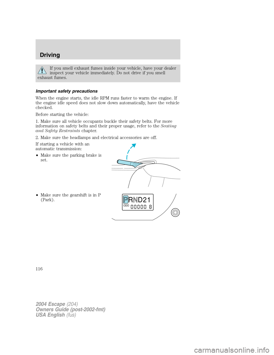
If starting a vehicle with an
automatic transmission:
•Make sure the parking brake is
set.
•Make sure the gearshift is in P
(Park).
R D 2 1ODO
2004 Escape(204)
Owners Guide (post-2002-fmt)
USA English(fus)
Driving
116
Page 156 of 240
If the battery has been disconnected and reconnected, refer to the
Batterysection of theMaintenance and specificationschapter.
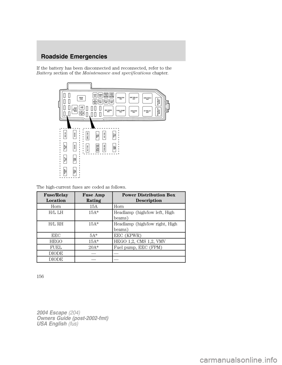
The high-current fuses are coded as follows.
Fuse/Relay
LocationFuse Amp
RatingPower Distribution Box
Description
Horn 15A Horn
H/L LH 15A* Headlamp (high/low left, High
beams)
H/L RH 15A* Headlamp (high/low right, High
beams)
EEC 5A* EEC (KPWR)
HEGO 15A* HEGO 1,2, CMS 1,2, VMV
FUEL 20A* Fuel pump, EEC (FPM)
DIODE — —
DIODE — —
MAIN
120A
HEGO
15A (HORN)
15A
FUEL
20ADIODE DIODE H/L LH
15AH/L RH
15AEEC 5A
INJ
30A
HTR
40A
BTN 1
40ABTN 240AR DEF30AIG
MAIN
40A
H/L
RELAY
MICRO
MAIN
FAN(ABS)
60A
ST RELAY
ISO DEF RELAY
ISOADD FAN 2
ISO
A/C RELAY
MICRO FOG RELAY
MICRO
MAIN FAN
ISO
ADD FAN
ISO EEC MAIN
ISOFUEL PUMP
ISO
ALT 15A
FOG 20A(DRL) 15A
PWR 1
15A DRL2 15A
HLEV 10A
(ABS)
25APWR 2
15A A/C 15A
40/50AADD
FAN
40/50A
HTD
SEATS
30A
2004 Escape(204)
Owners Guide (post-2002-fmt)
USA English(fus)
Roadside Emergencies
156
Page 157 of 240
Fuse/Relay
LocationFuse Amp
RatingPower Distribution Box
Description
H/L RELAY
MICRO— Headlamp (high/low, right/left
relay)
HTD SEATS 30A Heated seats (if equipped)
INJ 30A** EEC (VPWR), EVR, MAF, IAC,
Bulkhead, HEGO fuse
MAIN 120A Main
ALT 15A* Alternator/ Regulator
(DRL) 15A* Daytime Running Lamps (DRL)
unit (feed), DRL relay
(DRL2) (HLEV)15A*(DRL2)
10A(HLEV)DRL module, HLEV
PWR 1 15A* Auxiliary power point
FOG 20A* Foglamps, Foglamp indicator
A/C 15A* A/C clutch
(ABS) 25A* Anti-Lock Brake System (ABS)
SOL, EVAC & FILL
PWR 2 15A* Auxiliary power point
IG MAIN 40A** Starter
HTR 40A** Blower motor, Blower motor relay
BTN 1 40A** JB - Accessory relay, Radio, TNS
relay, Cigar lighter, Cluster, Power
mirror, GEM, Accessory delay
relay, Power windows, Power
moonroof
(ABS) 60A** ABS motor, EVAC & FILL
BTN 2 40A** JB - Radio, CD changer, Cluster,
Dome lamps, Map lamps, Cargo
lamps, Horn relay, GEM, Power
locks, Speed control
MAIN FAN 40A** (2.0 L)
50A(3.0 L)Main fan
R DEF 30A** Rear defroster
2004 Escape(204)
Owners Guide (post-2002-fmt)
USA English(fus)
Roadside Emergencies
157
Page 229 of 240
FORD ACCESSORIES FOR YOUR VEHICLE
A wide selection of genuine Ford accessories are available for your
vehicle through your local authorized Ford or Ford of Canada dealer.
These quality accessories have been specifically engineered to fulfill your
automotive needs; they are custom designed to complement the style
and aerodynamic appearance of your vehicle. In addition, each accessory
is made from high quality materials and meets or exceeds Ford’s rigorous
engineering and safety specifications. Ford Motor Company will repair or
replace any properly dealer-installed Ford accessory found to be
defective in factory-supplied materials or workmanship during the
warranty period, as well as any component damaged by the defective
accessory. The accessory will be warranted for whichever provides you
the greatest benefit:
•12 months or 20,000 km (12,000 miles) (whichever occurs first), or
•the remainder of your new vehicle limited warranty.
This means that genuine Ford accessories purchased along with your new
vehicle and installed by the dealer are covered for the full length of your
New Vehicle’s Limited Warranty — 3 years or 60,000 km (36,000 miles)
(whichever occurs first). Contact your dealer for details and a copy of the
warranty.
Not all accessories are available for all models.
Following is a list of several Ford Genuine Accessory products. Not all
accessories are available for all models. To find out what accessories are
available for your vehicle, please contact your dealer or visit our online
store at: www.fordaccessoriesstore.com.
Exterior style
Bug shields
Deflectors
Fender flares
Front end covers
Grille inserts
Headlamps, fog lights and Daytime Running Lamps (DRLS)
Running boards
Splash guards
Truck caps
Wheels
2004 Escape(204)
Owners Guide (post-2002-fmt)
USA English(fus)
Accessories
Accessories
229
Page 233 of 240
refill capacities ........................220
service points ..................188–189
starting after a collision .........150
Engine block heater .................118
Engine oil ..................................190
checking and adding ..............190
dipstick ....................................190
filter, specifications ........193, 220
recommendations ...................193
refill capacities ........................220
specifications ..................223, 225
Exhaust fumes ..........................118
F
Fluid capacities .........................220
Foglamps .....................................34
Four-Wheel Drive vehicles
driving off road .......................131
indicator light .........................130
preparing to drive your
vehicle .....................................121
Fuel ............................................201
calculating fuel economy .......205
cap ...........................................202
capacity ...................................220
choosing the right fuel ...........203
comparisons with EPA fuel
economy estimates .................208
detergent in fuel .....................204
filling your vehicle with
fuel ...........................201–202, 205
filter, specifications ........205, 220
fuel pump shut-off switch .....150
improving fuel economy ........205
octane rating ...................204, 225
quality ......................................204
running out of fuel .................204
safety information relating to
automotive fuels .....................201Fuses ..................................151–152
G
Garage door opener ....................46
Gas cap (see Fuel cap) ............202
Gas mileage (see Fuel
economy) ...................................205
Gauges .........................................13
GAWR (Gross Axle Weight
Rating) .......................................141
calculating ...............................143
definition .................................141
driving with a heavy load ......141
location ....................................141
GVWR (Gross Vehicle Weight
Rating) .......................................141
calculating .......................141, 143
definition .................................141
driving with a heavy load ......141
location ....................................141
H
Hazard flashers .........................150
Head restraints .....................75, 77
Headlamps ...................................34
aiming ........................................36
autolamp system .................34, 48
bulb specifications ....................39
daytime running lights .............34
flash to pass ..............................35
high beam .................................35
replacing bulbs .........................40
turning on and off ....................34
Heating
heater only system ...................31
Hood ..........................................187
2004 Escape(204)
Owners Guide (post-2002-fmt)
USA English(fus)
Index
233