clock FORD EXPEDITION 2016 3.G Owners Manual
[x] Cancel search | Manufacturer: FORD, Model Year: 2016, Model line: EXPEDITION, Model: FORD EXPEDITION 2016 3.GPages: 421, PDF Size: 6.3 MB
Page 139 of 421
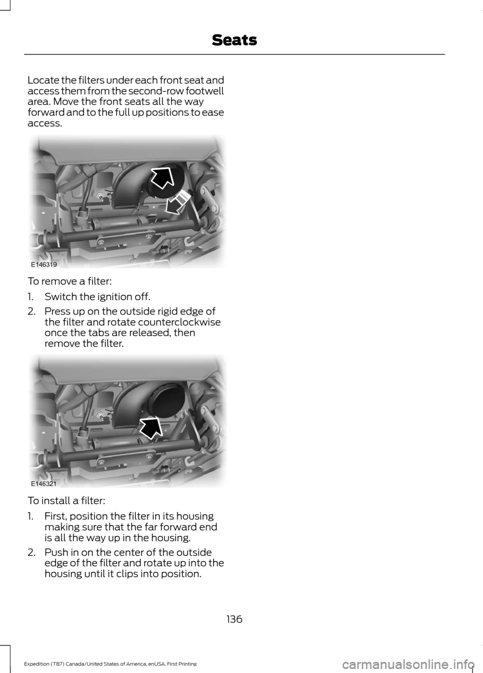
Locate the filters under each front seat and
access them from the second-row footwell
area. Move the front seats all the way
forward and to the full up positions to ease
access.
To remove a filter:
1. Switch the ignition off.
2. Press up on the outside rigid edge of
the filter and rotate counterclockwise
once the tabs are released, then
remove the filter. To install a filter:
1. First, position the filter in its housing
making sure that the far forward end
is all the way up in the housing.
2. Push in on the center of the outside edge of the filter and rotate up into the
housing until it clips into position.
136
Expedition (TB7) Canada/United States of America, enUSA, First Printing SeatsE146319 E146321
Page 200 of 421
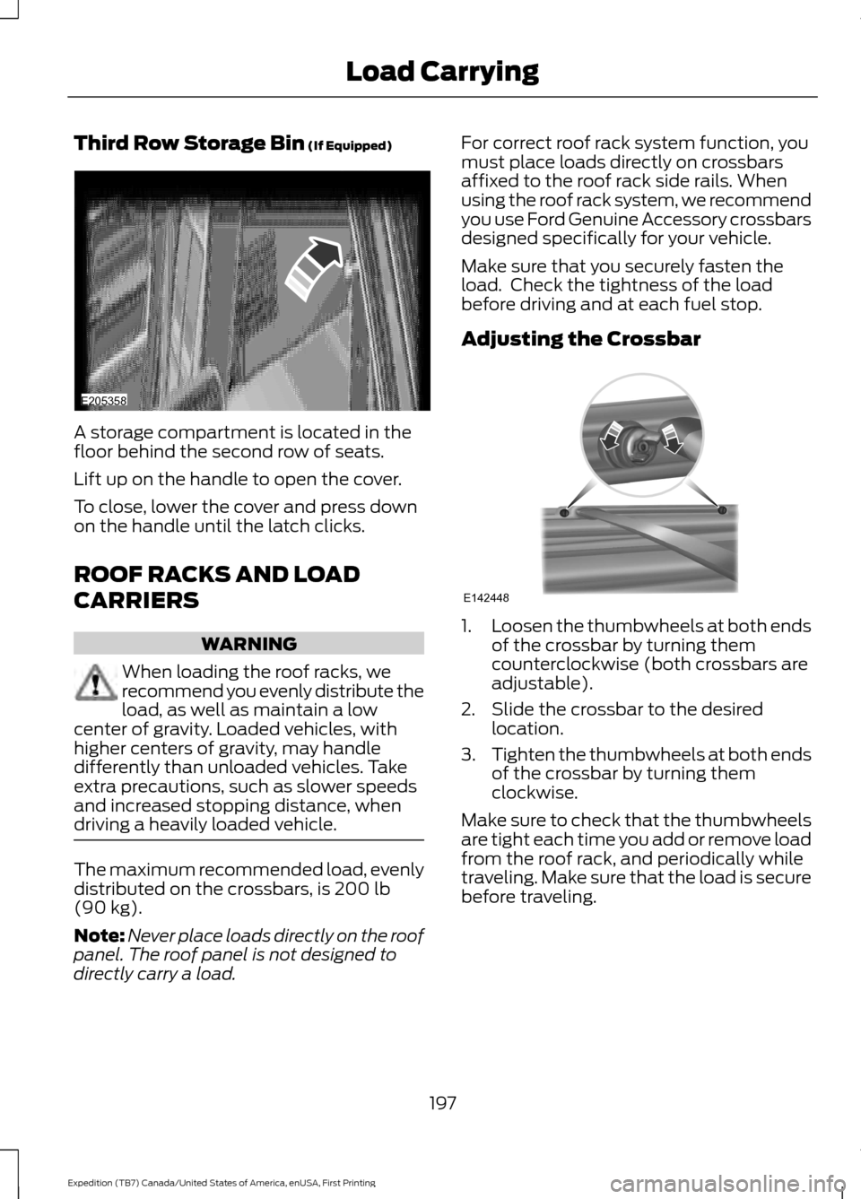
Third Row Storage Bin (If Equipped)
A storage compartment is located in the
floor behind the second row of seats.
Lift up on the handle to open the cover.
To close, lower the cover and press down
on the handle until the latch clicks.
ROOF RACKS AND LOAD
CARRIERS
WARNING
When loading the roof racks, we
recommend you evenly distribute the
load, as well as maintain a low
center of gravity. Loaded vehicles, with
higher centers of gravity, may handle
differently than unloaded vehicles. Take
extra precautions, such as slower speeds
and increased stopping distance, when
driving a heavily loaded vehicle. The maximum recommended load, evenly
distributed on the crossbars, is
200 lb
(90 kg).
Note: Never place loads directly on the roof
panel. The roof panel is not designed to
directly carry a load. For correct roof rack system function, you
must place loads directly on crossbars
affixed to the roof rack side rails. When
using the roof rack system, we recommend
you use Ford Genuine Accessory crossbars
designed specifically for your vehicle.
Make sure that you securely fasten the
load. Check the tightness of the load
before driving and at each fuel stop.
Adjusting the Crossbar
1.
Loosen the thumbwheels at both ends
of the crossbar by turning them
counterclockwise (both crossbars are
adjustable).
2. Slide the crossbar to the desired location.
3. Tighten the thumbwheels at both ends
of the crossbar by turning them
clockwise.
Make sure to check that the thumbwheels
are tight each time you add or remove load
from the roof rack, and periodically while
traveling. Make sure that the load is secure
before traveling.
197
Expedition (TB7) Canada/United States of America, enUSA, First Printing Load CarryingE205358 E142448
Page 249 of 421
Only use oils certified for gasoline engines
by the American Petroleum Institute (API).
An oil with this trademark symbol
conforms to the current engine and
emission system protection standards and
fuel economy requirements of the
International Lubricants Specification
Advisory Council (ILSAC), comprised of
U.S. and Japanese automobile
manufacturers.
1. Check the engine oil level.
2. If the engine oil level is not within the
normal range, add engine oil that
meets Ford specifications. See
Capacities and Specifications (page
303
).
3. Remove the engine oil filler cap and use a funnel to pour the engine oil into
the opening.
4. Wipe off any spilled oil.
5. Recheck the engine oil level. Make sure
the oil level is not above the normal
operating range on the engine oil level
dipstick.
6. Install the engine oil level dipstick and ensure it is fully seated.
7. Fully install the engine oil filler cap by turning the filler cap clockwise until
three clicks are heard or until the cap
is fully seated. OIL CHANGE INDICATOR
RESET
Use the information display controls on
the steering wheel to reset the oil change
indicator.
From the main menu scroll to:
Action and description
Message
Press the right arrow button,
then from this menu scroll
to the following message.
Settings
Press the right arrow button,
then from this menu scroll
to the following message.
Vehicle
Press the right arrow button,
then from this menu scroll
to the following message.
Oil Life
Press and hold the
OK
button until the instrument
cluster displays the
following message.
Hold OK to
Reset
Reset Successful
When the oil change indic-
ator resets the instrument
cluster displays 100%.
Remaining Life
{00}%
If the instrument cluster
displays one of the following
messages, repeat the
process.
Not Reset
Reset Cancelled
246
Expedition (TB7) Canada/United States of America, enUSA, First Printing MaintenanceE142732
Page 256 of 421
WARNINGS
Keep batteries out of reach of
children. Batteries contain sulfuric
acid. Avoid contact with skin, eyes or
clothing. Shield your eyes when working
near the battery to protect against possible
splashing of acid solution. In case of acid
contact with skin or eyes, flush
immediately with water for a minimum of
15 minutes and get prompt medical
attention. If acid is swallowed, call a
physician immediately. Battery posts, terminals and related
accessories contain lead and lead
compounds. Wash hands after
handling. This vehicle may be fitted with more
than one battery. Removing the
battery cables from only one battery
does not disconnect your vehicle electrical
system. Make sure you disconnect the
battery cables from all batteries when
disconnecting power. Failure to do so may
cause serious personal injury or property
damage. Your vehicle is fitted with a Motorcraft
maintenance-free battery which normally
does not require additional water.
When a battery replacement is required,
you must use a recommended
replacement battery that matches the
electrical requirements of the vehicle.
Note:
After cleaning or replacing the
battery, make sure you reinstall the battery
cover or shield.
Note: If you add electrical accessories or
components to the vehicle, it may adversely
affect the low voltage battery performance
and durability. This may also affect the
performance of other electrical systems in
the vehicle.
For longer, trouble-free operation, keep the
top of the battery clean and dry. If you see any corrosion on the battery or
terminals, remove the cables from the
terminals and clean with a wire brush. You
can neutralize the acid with a solution of
baking soda and water.
Because your vehicle
’s engine is
electronically controlled by a computer,
some control conditions are maintained
by power from the battery. When the
battery is disconnected or a new battery
is installed, the engine must relearn its idle
and fuel trim strategy for optimum
driveability and performance. Flexible fuel
vehicles (FFV) must also relearn the
ethanol content of the fuel for optimum
driveability and performance.
To restore the settings, do the following:
1. Apply the parking brake.
2. Shift into park (P) or neutral (N).
3. Switch off all accessories.
4. Press the brake pedal and start your vehicle.
5. Run the engine until it reaches normal operating temperature. While the
engine is warming up, complete the
following: Reset the clock. See Audio
System (page 312). Reset the power
windows bounce-back feature. See
Windows and Mirrors
(page 80).
Reset the radio station presets. See
Audio System
(page 312).
6. Allow the engine to idle for at least one
minute.
7. Drive the vehicle at least 10 mi (16 km)
to completely relearn the idle trim and
fuel trim strategy.
Note: If you do not allow the engine to
relearn the idle and fuel trim strategy, the
idle quality of your vehicle may be adversely
affected until the engine computer
eventually relearns the idle trim and fuel
trim strategy.
253
Expedition (TB7) Canada/United States of America, enUSA, First Printing Maintenance
Page 259 of 421
Vertical Aim Adjustment
1. Park your vehicle directly in front of a
wall or screen on a level surface,
approximately 25 feet (7.6 meters)
away.
2. Measure the height from the center of your headlamp (indicated by a 3.0
millimeter circle on the lens) to the
ground and mark an 8 foot (2.4 meter)
horizontal reference line on the vertical
wall or screen at this height (a piece of
masking tape works well).
Note: To see a clearer light pattern for
adjusting, you may want to block the light
from one headlamp while adjusting the
other.
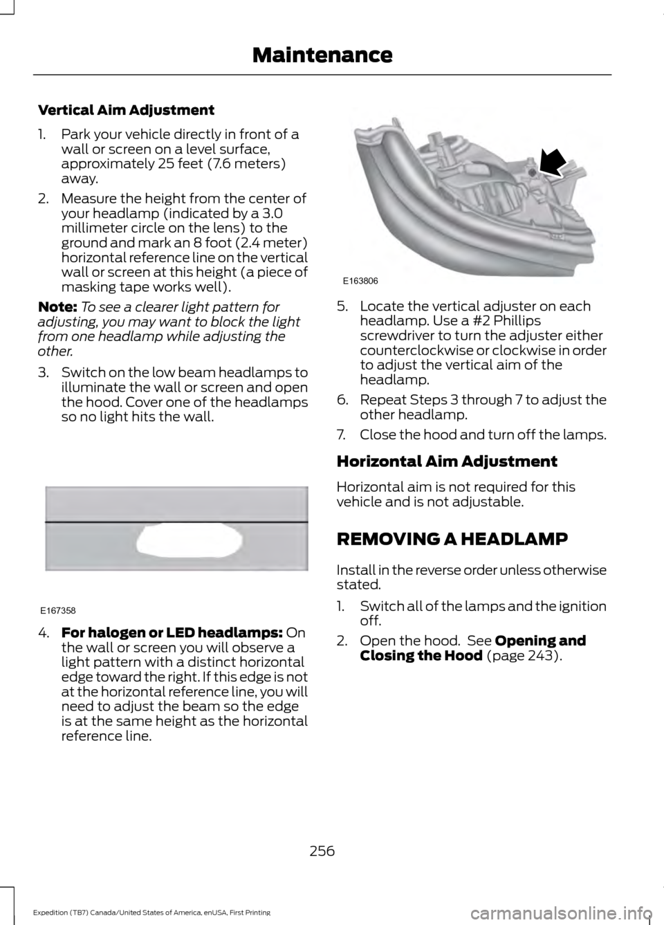
3. Switch on the low beam headlamps to
illuminate the wall or screen and open
the hood. Cover one of the headlamps
so no light hits the wall. 4.
For halogen or LED headlamps: On
the wall or screen you will observe a
light pattern with a distinct horizontal
edge toward the right. If this edge is not
at the horizontal reference line, you will
need to adjust the beam so the edge
is at the same height as the horizontal
reference line. 5. Locate the vertical adjuster on each
headlamp. Use a #2 Phillips
screwdriver to turn the adjuster either
counterclockwise or clockwise in order
to adjust the vertical aim of the
headlamp.
6. Repeat Steps 3 through 7 to adjust the
other headlamp.
7. Close the hood and turn off the lamps.
Horizontal Aim Adjustment
Horizontal aim is not required for this
vehicle and is not adjustable.
REMOVING A HEADLAMP
Install in the reverse order unless otherwise
stated.
1. Switch all of the lamps and the ignition
off.
2. Open the hood. See Opening and
Closing the Hood (page 243).
256
Expedition (TB7) Canada/United States of America, enUSA, First Printing MaintenanceE167358 E163806
Page 260 of 421
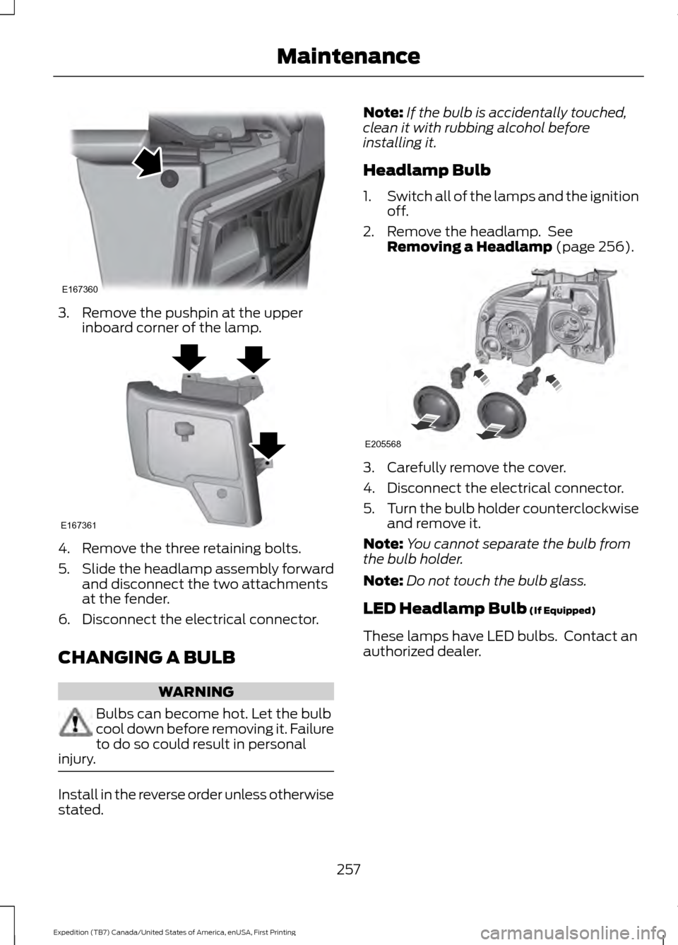
3. Remove the pushpin at the upper
inboard corner of the lamp. 4. Remove the three retaining bolts.
5.
Slide the headlamp assembly forward
and disconnect the two attachments
at the fender.
6. Disconnect the electrical connector.
CHANGING A BULB WARNING
Bulbs can become hot. Let the bulb
cool down before removing it. Failure
to do so could result in personal
injury. Install in the reverse order unless otherwise
stated. Note:
If the bulb is accidentally touched,
clean it with rubbing alcohol before
installing it.
Headlamp Bulb
1. Switch all of the lamps and the ignition
off.
2. Remove the headlamp. See Removing a Headlamp (page 256). 3. Carefully remove the cover.
4. Disconnect the electrical connector.
5.
Turn the bulb holder counterclockwise
and remove it.
Note: You cannot separate the bulb from
the bulb holder.
Note: Do not touch the bulb glass.
LED Headlamp Bulb
(If Equipped)
These lamps have LED bulbs. Contact an
authorized dealer.
257
Expedition (TB7) Canada/United States of America, enUSA, First Printing MaintenanceE167360 E167361 E205568
Page 261 of 421
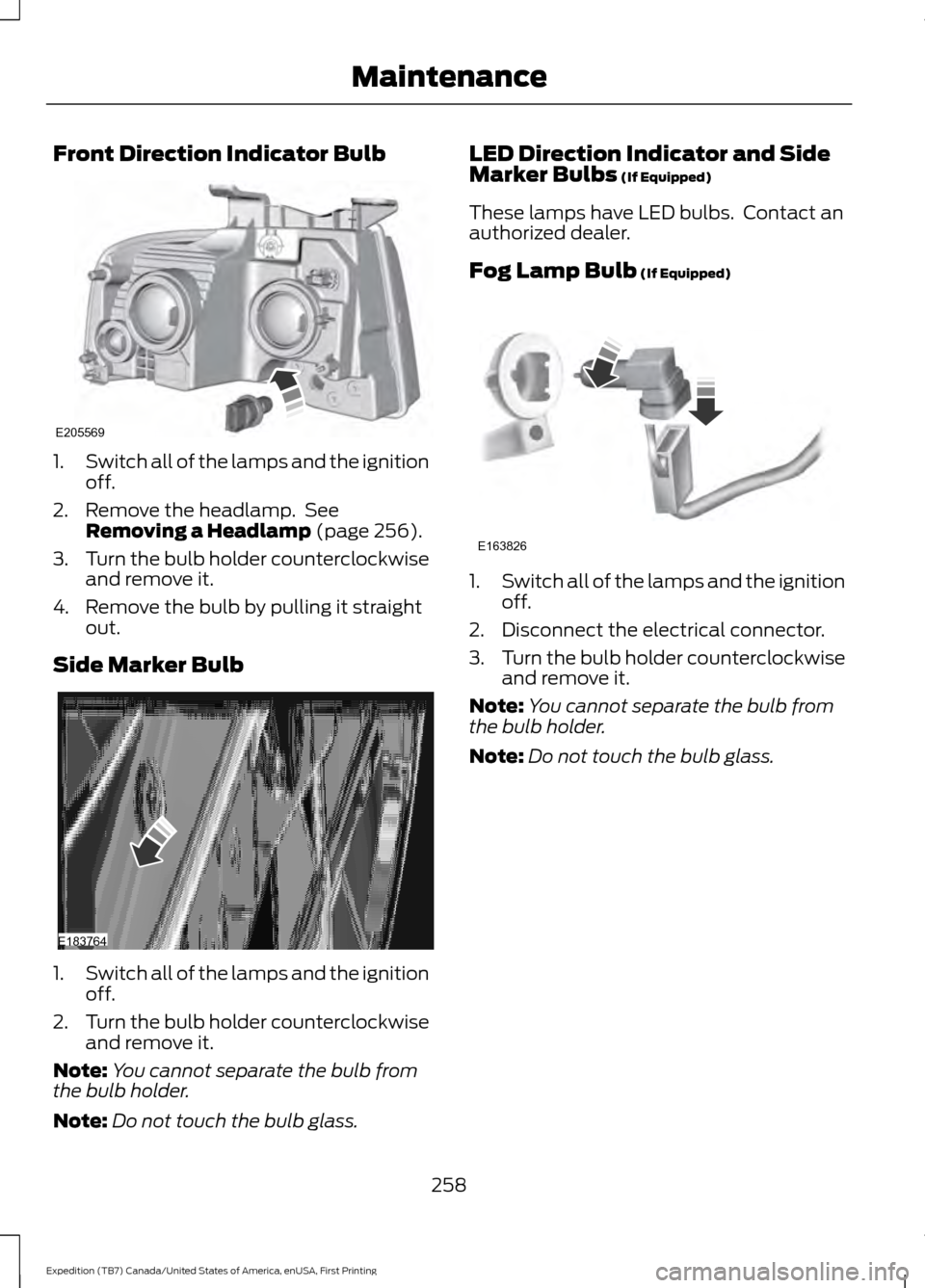
Front Direction Indicator Bulb
1.
Switch all of the lamps and the ignition
off.
2. Remove the headlamp. See Removing a Headlamp (page 256).
3. Turn the bulb holder counterclockwise
and remove it.
4. Remove the bulb by pulling it straight out.
Side Marker Bulb 1.
Switch all of the lamps and the ignition
off.
2. Turn the bulb holder counterclockwise
and remove it.
Note: You cannot separate the bulb from
the bulb holder.
Note: Do not touch the bulb glass. LED Direction Indicator and Side
Marker Bulbs
(If Equipped)
These lamps have LED bulbs. Contact an
authorized dealer.
Fog Lamp Bulb
(If Equipped) 1.
Switch all of the lamps and the ignition
off.
2. Disconnect the electrical connector.
3. Turn the bulb holder counterclockwise
and remove it.
Note: You cannot separate the bulb from
the bulb holder.
Note: Do not touch the bulb glass.
258
Expedition (TB7) Canada/United States of America, enUSA, First Printing MaintenanceE205569 E183764 E163826
Page 262 of 421
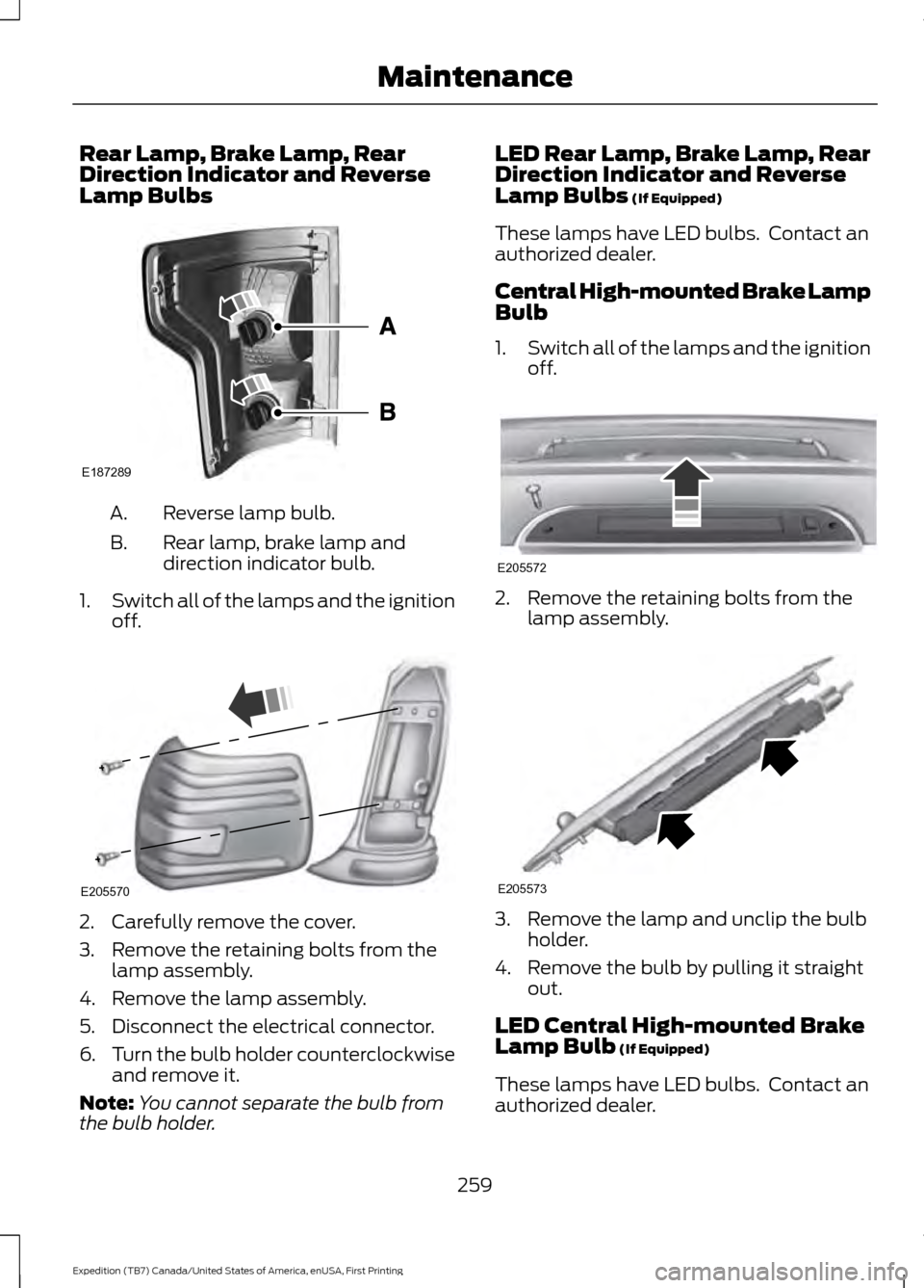
Rear Lamp, Brake Lamp, Rear
Direction Indicator and Reverse
Lamp Bulbs
Reverse lamp bulb.
A.
Rear lamp, brake lamp and
direction indicator bulb.
B.
1. Switch all of the lamps and the ignition
off. 2. Carefully remove the cover.
3. Remove the retaining bolts from the
lamp assembly.
4. Remove the lamp assembly.
5. Disconnect the electrical connector.
6. Turn the bulb holder counterclockwise
and remove it.
Note: You cannot separate the bulb from
the bulb holder. LED Rear Lamp, Brake Lamp, Rear
Direction Indicator and Reverse
Lamp Bulbs (If Equipped)
These lamps have LED bulbs. Contact an
authorized dealer.
Central High-mounted Brake Lamp
Bulb
1. Switch all of the lamps and the ignition
off. 2. Remove the retaining bolts from the
lamp assembly. 3. Remove the lamp and unclip the bulb
holder.
4. Remove the bulb by pulling it straight out.
LED Central High-mounted Brake
Lamp Bulb
(If Equipped)
These lamps have LED bulbs. Contact an
authorized dealer.
259
Expedition (TB7) Canada/United States of America, enUSA, First Printing MaintenanceE187289 E205570 E205572 E205573
Page 263 of 421
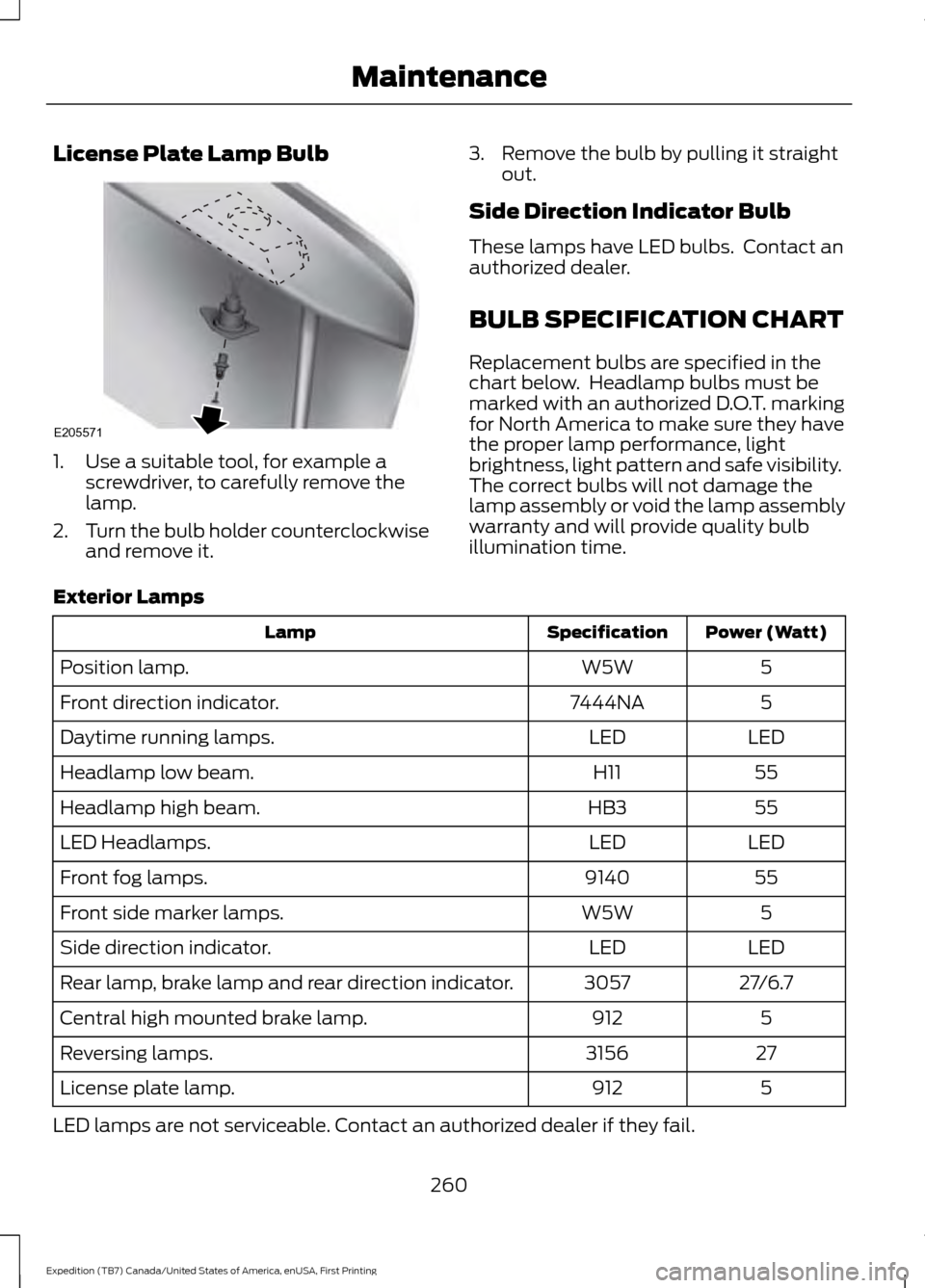
License Plate Lamp Bulb
1. Use a suitable tool, for example a
screwdriver, to carefully remove the
lamp.
2. Turn the bulb holder counterclockwise
and remove it. 3. Remove the bulb by pulling it straight
out.
Side Direction Indicator Bulb
These lamps have LED bulbs. Contact an
authorized dealer.
BULB SPECIFICATION CHART
Replacement bulbs are specified in the
chart below. Headlamp bulbs must be
marked with an authorized D.O.T. marking
for North America to make sure they have
the proper lamp performance, light
brightness, light pattern and safe visibility.
The correct bulbs will not damage the
lamp assembly or void the lamp assembly
warranty and will provide quality bulb
illumination time.
Exterior Lamps Power (Watt)
Specification
Lamp
5
W5W
Position lamp.
5
7444NA
Front direction indicator.
LED
LED
Daytime running lamps.
55
H11
Headlamp low beam.
55
HB3
Headlamp high beam.
LED
LED
LED Headlamps.
55
9140
Front fog lamps.
5
W5W
Front side marker lamps.
LED
LED
Side direction indicator.
27/6.7
3057
Rear lamp, brake lamp and rear direction indicator.
5
912
Central high mounted brake lamp.
27
3156
Reversing lamps.
5
912
License plate lamp.
LED lamps are not serviceable. Contact an authorized dealer if they fail.
260
Expedition (TB7) Canada/United States of America, enUSA, First Printing MaintenanceE205571
Page 298 of 421
•
To reduce the chances of interference
from another vehicle, perform the
system reset procedure at least three
feet (one meter) away from another
Ford Motor Company vehicle
undergoing the system reset procedure
at the same time.
• Do not wait more than two minutes
between resetting each tire sensor or
the system will time-out and the entire
procedure will have to be repeated on
all four wheels.
• A double horn will sound indicating the
need to repeat the procedure.
Performing the System Reset Procedure
Read the entire procedure before
attempting.
1. Drive the vehicle above 20 mph (32 km/h) for at least two minutes, then
park in a safe location where you can
easily get to all four tires and have
access to an air pump.
2. Place the ignition in the off position and
keep the key in the ignition.
3. Cycle the ignition to the on position with the engine off.
4. Turn the hazard flashers on then off three times. You must accomplish this
within 10 seconds. If the reset mode
has been entered successfully, the horn
will sound once, the system indicator
will flash and a message is shown in
the information display. If this does not
occur, please try again starting at Step
2. If after repeated attempts to enter
the reset mode, the horn does not
sound, the system indicator does not
flash and no message is shown in the
information display, seek service from
your authorized dealer. 5. Train the tire pressure monitoring
system sensors in the tires using the
following system reset sequence
starting with the left front tire in the
following clockwise order: Left front
(driver's side front tire), Right front
(passenger's side front tire), Right rear
(passenger's side rear tire), Left rear
(driver's side rear tire).
6. Remove the valve cap from the valve stem on the left front tire. Decrease the
air pressure until the horn sounds.
Note: The single horn chirp confirms
that the sensor identification code has
been learned by the module for this
position. If a double horn is heard, the
reset procedure was unsuccessful, and
you must repeat it.
7. Remove the valve cap from the valve stem on the right front tire. Decrease
the air pressure until the horn sounds.
8. Remove the valve cap from the valve stem on the right rear tire. Decrease the
air pressure until the horn sounds.
9. Remove the valve cap from the valve stem on the left rear tire. Decrease the
air pressure until the horn sounds.
Training is complete after the horn
sounds for the last tire trained (driver's
side rear tire), the system indicator
stops flashing, and a message is shown
in the information display.
10. Turn the ignition off. If two short horn
beeps are heard, the reset procedure
was unsuccessful and you must
repeat it. If after repeating the
procedure and two short beeps are
heard when the ignition is turned to
off, seek assistance from your
authorized dealer.
295
Expedition (TB7) Canada/United States of America, enUSA, First Printing Wheels and Tires