roof FORD EXPLORER 2016 5.G Owners Manual
[x] Cancel search | Manufacturer: FORD, Model Year: 2016, Model line: EXPLORER, Model: FORD EXPLORER 2016 5.GPages: 541, PDF Size: 6.51 MB
Page 5 of 541
Steering Wheel
Adjusting the Steering Wheel - Vehicles
With: Manual Adjustable Steering
Column...........................................................72
Adjusting the Steering Wheel -
Vehicles
With: Power Adjustable Steering
Column...........................................................72
Audio Control...................................................73
Voice Control
....................................................74
Cruise Control
..................................................74
Information Display Control.......................75
Heated Steering Wheel................................75
Pedals
Adjusting the Pedals
.....................................76
Wipers and Washers
Windshield Wipers
.........................................77
Autowipers........................................................77
Windshield Washers
.....................................78
Rear Window Wiper and Washers...........78
Lighting
General Information
.....................................80
Lighting Control
..............................................80
Autolamps
.........................................................81
Instrument Lighting Dimmer.....................82
Headlamp Exit Delay
....................................82
Daytime Running Lamps
.............................82
Automatic High Beam Control.................83
Front Fog Lamps............................................84
Direction Indicators
.......................................85
Interior Lamps
.................................................85
Windows and Mirrors
Power Windows
..............................................87
Exterior Mirrors
................................................88
Interior Mirror...................................................90
Sun Visors
..........................................................91
Moonroof............................................................91 Instrument Cluster
Gauges...............................................................93
Warning Lamps and Indicators................96
Audible Warnings and Indicators
...........100
Information Displays
General Information.....................................101
Information Messages
.................................115
Climate Control
Manual Climate Control.............................129
Automatic Climate Control -
Vehicles
With: Premium AM/FM/CD...................131
Automatic Climate Control -
Vehicles
With: Sony Audio System......................132
Hints on Controlling the Interior Climate.........................................................134
Rear Passenger Climate Controls...........137
Heated Windows and Mirrors..................138
Cabin Air Filter
...............................................138
Remote Start.................................................139
Seats
Sitting in the Correct Position
.................140
Head Restraints............................................140
Manual Seats
.................................................143
Power Seats
...................................................144
Memory Function
.........................................146
Rear Seats
.......................................................147
Heated Seats.................................................154
Climate Controlled Seats..........................155
Universal Garage Door Opener
Universal Garage Door Opener................157
Auxiliary Power Points
Auxiliary Power Points................................162
2
Explorer (TUB), enUSA, First Printing Table of Contents
Page 6 of 541
Storage Compartments
Center Console..............................................164
Overhead Console.......................................164
Starting and Stopping the Engine
General Information
....................................165
Ignition Switch
...............................................165
Keyless Starting............................................165
Starting a Gasoline Engine.......................166
Engine Block Heater....................................169
Fuel and Refueling
Safety Precautions
........................................171
Fuel Quality.....................................................172
Fuel Quality - E85.........................................172
Fuel Filler Funnel Location........................173
Running Out of Fuel
.....................................173
Refueling..........................................................174
Fuel Consumption
........................................176
Emission Control System...........................177
Transmission
Automatic Transmission...........................180
Four-Wheel Drive
Principle of Operation
................................184
Using Four-Wheel Drive.............................184
Brakes
General Information
....................................189
Hints on Driving With Anti-Lock Brakes...........................................................189
Parking Brake.................................................190
Hill Start Assist.............................................190
Traction Control
Principle of Operation.................................192
Using Traction Control................................192 Stability Control
Principle of Operation.................................193
Using Stability Control...............................194
Terrain Response
Using Terrain Response.............................195
Using Hill Descent Control........................196
Parking Aids
Principle of Operation................................198
Rear Parking Aid
...........................................198
Front Parking Aid..........................................199
Side Sensing System.................................200
Active Park Assist
........................................202
Rear View Camera
......................................208
180 Degree Parking Aid Camera..............211
Cruise Control
Principle of Operation.................................213
Using Cruise Control....................................213
Using Adaptive Cruise Control.................214
Driving Aids
Driver Alert
.....................................................220
Lane Keeping System
................................220
Blind Spot Information System..............224
Cross Traffic Alert.........................................227
Steering...........................................................229
Pre-Collision Assist.....................................230
Load Carrying
Rear Under Floor Storage.........................233
Cargo Nets
......................................................233
Luggage Covers
............................................234
Roof Racks and Load Carriers................234
Load Limit.......................................................235
Towing
Towing a Trailer
............................................243
3
Explorer (TUB), enUSA, First Printing Table of Contents
Page 33 of 541
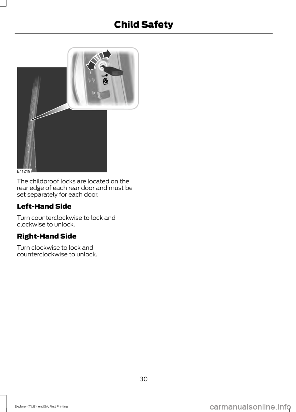
The childproof locks are located on the
rear edge of each rear door and must be
set separately for each door.
Left-Hand Side
Turn counterclockwise to lock and
clockwise to unlock.
Right-Hand Side
Turn clockwise to lock and
counterclockwise to unlock.
30
Explorer (TUB), enUSA, First Printing Child SafetyE112197
Page 49 of 541
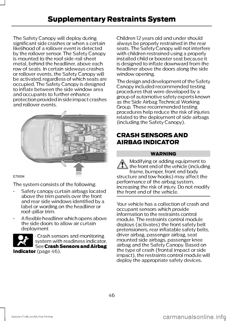
The Safety Canopy will deploy during
significant side crashes or when a certain
likelihood of a rollover event is detected
by the rollover sensor. The Safety Canopy
is mounted to the roof side-rail sheet
metal, behind the headliner, above each
row of seats. In certain sideways crashes
or rollover events, the Safety Canopy will
be activated, regardless of which seats are
occupied. The Safety Canopy is designed
to inflate between the side window area
and occupants to further enhance
protection provided in side impact crashes
and rollover events.
The system consists of the following:
•
Safety canopy curtain airbags located
above the trim panels over the front
and rear side windows identified by a
label or wording on the headliner or
roof-pillar trim.
• A flexible headliner which opens above
the side doors to allow air curtain
deployment · Crash sensors and monitoring
system with readiness indicator.
See Crash Sensors and Airbag
Indicator (page 46). Children 12 years old and under should
always be properly restrained in the rear
seats. The Safety Canopy will not interfere
with children restrained using a properly
installed child or booster seat because it
is designed to inflate downward from the
headliner above the doors along the side
window opening.
The design and development of the Safety
Canopy included recommended testing
procedures that were developed by a
group of automotive safety experts known
as the Side Airbag Technical Working
Group. These recommended testing
procedures help reduce the risk of injuries
related to the deployment of side airbags
(including the Safety Canopy).
CRASH SENSORS AND
AIRBAG INDICATOR
WARNING
Modifying or adding equipment to
the front end of the vehicle (including
frame, bumper, front end body
structure and tow hooks) may affect the
performance of the airbag system,
increasing the risk of injury. Do not modify
the front end of the vehicle. Your vehicle has a collection of crash and
occupant sensors which provide
information to the restraints control
module. The restraints control module
deploys (activates) the front safety belt
pretensioners, rear inflatable safety belts,
driver airbag, passenger airbag, seat
mounted side airbags, passenger knee
airbag and the Safety Canopy. Based on
the type of crash (frontal impact or side
impact), the restraints control module will
deploy the appropriate safety devices.
46
Explorer (TUB), enUSA, First Printing Supplementary Restraints SystemE75004
Page 94 of 541
SUN VISORS
Rotate the sun visor toward the side
window and extend it rearward for extra
shade.
Illuminated Vanity Mirror (If Equipped)
Lift the cover to switch the lamp on.
MOONROOF
(If Equipped)
WARNINGS
Do not let children play with the
moonroof or leave them unattended
in the vehicle. They may seriously
hurt themselves. WARNINGS
When closing the moonroof, you
should verify that it is free of
obstructions and make sure that
children and pets are not in the proximity
of the roof opening. The moonroof controls are located on the
overhead console and have a one-touch
open and close feature. To stop it during
one-touch operation, press the control a
second time.
Opening and Closing the
Sunscreen
Press and release the control to open the
sunscreen.
Note:
The sunscreen stops at the first panel
for the dual panel moonroof. Press and
release again to continue to open the
sunscreen past the second panel.
Pull and release the control to close the
sunscreen. The moonroof, if open,
automatically closes prior to closing the
sunscreen.
Opening and Closing the Moonroof
Press and release the
SLIDE control to
open the moonroof. The sunscreen, if
closed, automatically opens prior to
opening the moonroof. The moonroof
stops short of the fully opened position.
91
Explorer (TUB), enUSA, First Printing Windows and MirrorsE138666 E162197 E193983
Page 95 of 541
Note:
This position helps to reduce wind
noise or rumbling which may happen with
the moonroof fully open. Press and release
the control again to fully open the
moonroof.
Pull and release the SLIDE control to close
the moonroof.
Bounce-Back
The moonroof stops automatically while
closing. It reverses some distance if there
is an obstacle in the way.
Pull and hold the SLIDE control within two
seconds of a bounce-back event to
override this function. While bounce-back
is active, the closing force increases for
each of the next three times that you close
the moonroof.
Venting the Moonroof
Press and release the TILT control to vent
the moonroof. Pull and hold the TILT
control to close the moonroof.
92
Explorer (TUB), enUSA, First Printing Windows and Mirrors
Page 196 of 541
PRINCIPLE OF OPERATION
WARNINGS
Vehicle modifications involving
braking system, aftermarket roof
racks, suspension, steering system,
tire construction and wheel and tire size
may change the handling characteristics
of your vehicle and may adversely affect
the performance of the electronic stability
control system. In addition, installing any
stereo loudspeakers may interfere with
and adversely affect the electronic stability
control system. Install any aftermarket
stereo loudspeaker as far as possible from
the front center console, the tunnel, and
the front seats in order to minimize the risk
of interfering with the electronic stability
control sensors. Reducing the
effectiveness of the electronic stability
control system could lead to an increased
risk of loss of vehicle control, vehicle
rollover, personal injury and death. Remember that even advanced
technology cannot defy the laws of
physics. It’
s always possible to lose
control of a vehicle due to inappropriate
driver input for the conditions. Aggressive
driving on any road condition can cause
you to lose control of your vehicle
increasing the risk of personal injury or
property damage. Activation of the
electronic stability control system is an
indication that at least some of the tires
have exceeded their ability to grip the road;
this could reduce the operator ’s ability to
control the vehicle potentially resulting in
a loss of vehicle control, vehicle rollover,
personal injury and death. If your electronic
stability control system activates, SLOW
DOWN. The system automatically turns on each
time you switch the ignition on. If a driving condition activates either the
stability control or the traction control
system you may experience the following
conditions:
•
The stability and traction control light
flashes.
• Your vehicle slows down.
• Reduced engine power.
• A vibration in the brake pedal.
• The brake pedal is stiffer than usual.
• If the driving condition is severe and
your foot is not on the brake, the brake
pedal may move as the systems
applies higher brake forces.
The stability control system has several
features built into it to help you maintain
control of your vehicle:
Electronic Stability Control
The system enhances your vehicle ’s ability
to prevent skids or lateral slides by
applying brakes to one or more of the
wheels individually and, if necessary,
reducing engine power.
Roll Stability Control
The system enhances your vehicle ’s ability
to prevent rollovers by detecting your
vehicle ’s roll motion and the rate at which
it changes by applying the brakes to one
or more wheels individually.
Curve Control
The system enhances your vehicle ’s ability
to follow the road when cornering severely
or avoiding objects in the roadway. Curve
Control operates by reducing engine power
and, if necessary, applying brakes to one
or more of the wheels individually.
193
Explorer (TUB), enUSA, First Printing Stability Control
Page 205 of 541
•
The anti-lock brake system is
activated.
• The traction control system is
activated.
ACTIVE PARK ASSIST
Parallel Parking, Perpendicular
Parking, Park Out Assist WARNINGS
You must remain in your vehicle
when the system turns on. You are
responsible at all times for
controlling your vehicle, supervising the
system and intervening if required. Failure
to take care may result in the loss of
control of your vehicle, serious personal
injury or death. The sensors may not detect objects
in heavy rain or other conditions that
cause disruptive reflections.
Note:
The driver is always responsible for
controlling the vehicle, supervising the
system and intervening if required by
grabbing the steering wheel or pushing the
active park assist button.
The system detects an available parallel
or perpendicular parking space and
automatically steers your vehicle into the
space (hands-free) while you control the
accelerator, gearshift and brakes. The
system visually and audibly guides you to
park your vehicle.
If you are uncomfortable with the proximity
to any vehicle or object, you may choose
to override the system.
Park Out Assist automatically steers your
vehicle out of a parallel parking space
(hands-free) while you control the
accelerator, gearshift and brakes. The
system visually and audibly guides you to
enter traffic. Note:
The Blind Spot Information System
does not detect traffic alongside or behind
your vehicle during a park assist maneuver.
The system may not correctly operate in
any of the following conditions:
• You use a spare tire or a tire
significantly worn more than the other
tires.
• You use a unauthorized tire size.
• You try to park on a tight curve.
• Something passes between the front
bumper and the parking space (a
pedestrian or cyclist).
• The edge of the neighboring parked
vehicle is high off the ground (for
example, a bus, tow truck or flatbed
truck).
• The weather conditions are poor
(heavy rain, snow, fog, etc).
Note: Keep the sensors, located on the
bumper or fascia, free from snow, ice and
large accumulations of dirt. Covered sensors
can affect the system's accuracy. Do not
clean the sensors with sharp objects.
Note: The sensors may not detect objects
with surfaces that absorb ultrasonic waves
or cause ultrasonic interference (motorcycle
exhaust, truck air brakes or horns).
Do not use the system if:
• You have attached a foreign object
(bike rack or trailer) to the front or rear
of your vehicle or close to the sensors.
• You have attached an overhanging
object (surfboard) to the roof.
• A foreign object damages or obstructs
the front or rear bumper or side
sensors.
• The correct tire size is not in use on your
vehicle (for example, a mini-spare tire).
202
Explorer (TUB), enUSA, First Printing Parking Aids
Page 237 of 541
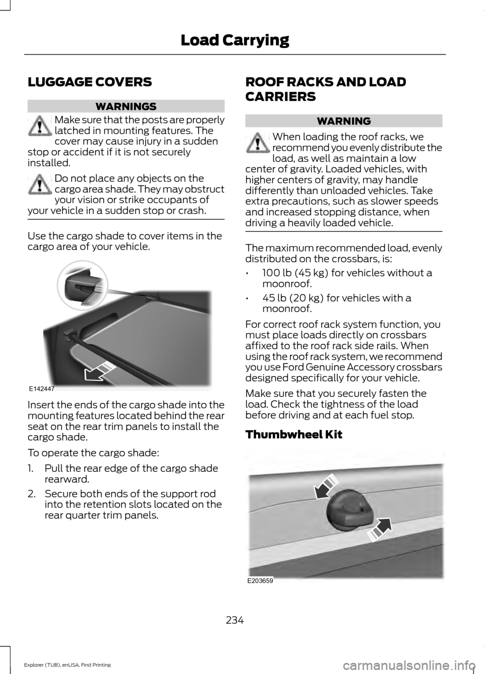
LUGGAGE COVERS
WARNINGS
Make sure that the posts are properly
latched in mounting features. The
cover may cause injury in a sudden
stop or accident if it is not securely
installed. Do not place any objects on the
cargo area shade. They may obstruct
your vision or strike occupants of
your vehicle in a sudden stop or crash. Use the cargo shade to cover items in the
cargo area of your vehicle.
Insert the ends of the cargo shade into the
mounting features located behind the rear
seat on the rear trim panels to install the
cargo shade.
To operate the cargo shade:
1. Pull the rear edge of the cargo shade
rearward.
2. Secure both ends of the support rod into the retention slots located on the
rear quarter trim panels. ROOF RACKS AND LOAD
CARRIERS WARNING
When loading the roof racks, we
recommend you evenly distribute the
load, as well as maintain a low
center of gravity. Loaded vehicles, with
higher centers of gravity, may handle
differently than unloaded vehicles. Take
extra precautions, such as slower speeds
and increased stopping distance, when
driving a heavily loaded vehicle. The maximum recommended load, evenly
distributed on the crossbars, is:
•
100 lb (45 kg) for vehicles without a
moonroof.
• 45 lb (20 kg)
for vehicles with a
moonroof.
For correct roof rack system function, you
must place loads directly on crossbars
affixed to the roof rack side rails. When
using the roof rack system, we recommend
you use Ford Genuine Accessory crossbars
designed specifically for your vehicle.
Make sure that you securely fasten the
load. Check the tightness of the load
before driving and at each fuel stop.
Thumbwheel Kit 234
Explorer (TUB), enUSA, First Printing Load CarryingE142447 E203659
Page 238 of 541
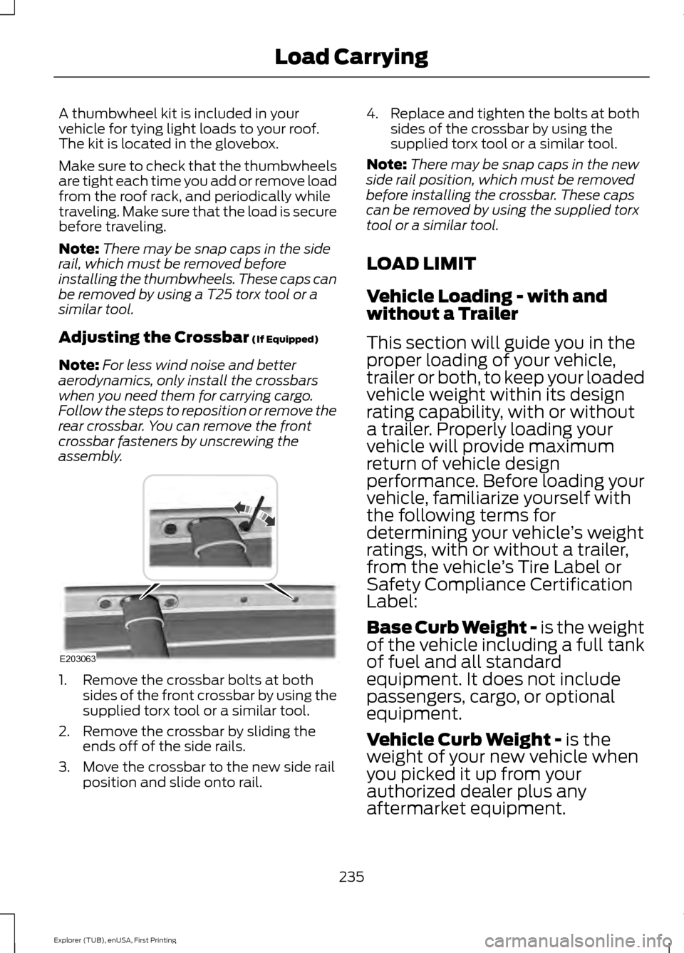
A thumbwheel kit is included in your
vehicle for tying light loads to your roof.
The kit is located in the glovebox.
Make sure to check that the thumbwheels
are tight each time you add or remove load
from the roof rack, and periodically while
traveling. Make sure that the load is secure
before traveling.
Note:
There may be snap caps in the side
rail, which must be removed before
installing the thumbwheels. These caps can
be removed by using a T25 torx tool or a
similar tool.
Adjusting the Crossbar (If Equipped)
Note: For less wind noise and better
aerodynamics, only install the crossbars
when you need them for carrying cargo.
Follow the steps to reposition or remove the
rear crossbar. You can remove the front
crossbar fasteners by unscrewing the
assembly. 1. Remove the crossbar bolts at both
sides of the front crossbar by using the
supplied torx tool or a similar tool.
2. Remove the crossbar by sliding the ends off of the side rails.
3. Move the crossbar to the new side rail position and slide onto rail. 4. Replace and tighten the bolts at both
sides of the crossbar by using the
supplied torx tool or a similar tool.
Note: There may be snap caps in the new
side rail position, which must be removed
before installing the crossbar. These caps
can be removed by using the supplied torx
tool or a similar tool.
LOAD LIMIT
Vehicle Loading - with and
without a Trailer
This section will guide you in the
proper loading of your vehicle,
trailer or both, to keep your loaded
vehicle weight within its design
rating capability, with or without
a trailer. Properly loading your
vehicle will provide maximum
return of vehicle design
performance. Before loading your
vehicle, familiarize yourself with
the following terms for
determining your vehicle ’s weight
ratings, with or without a trailer,
from the vehicle ’s Tire Label or
Safety Compliance Certification
Label:
Base Curb Weight -
is the weight
of the vehicle including a full tank
of fuel and all standard
equipment. It does not include
passengers, cargo, or optional
equipment.
Vehicle Curb Weight -
is the
weight of your new vehicle when
you picked it up from your
authorized dealer plus any
aftermarket equipment.
235
Explorer (TUB), enUSA, First Printing Load CarryingE203063