clock FORD F-150 2018 Owners Manual
[x] Cancel search | Manufacturer: FORD, Model Year: 2018, Model line: F-150, Model: FORD F-150 2018Pages: 641, PDF Size: 8.37 MB
Page 38 of 641
Note:
The child restraint must rest tightly
against the vehicle seat upon which it is
installed. It may be necessary to lift or
remove the head restraint. See Seats (page
151).
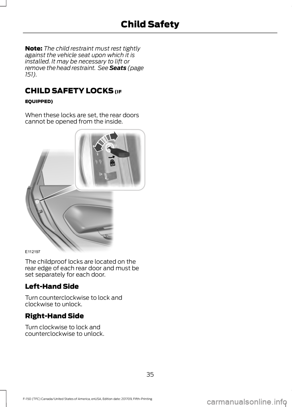
CHILD SAFETY LOCKS
(IF
EQUIPPED)
When these locks are set, the rear doors
cannot be opened from the inside. The childproof locks are located on the
rear edge of each rear door and must be
set separately for each door.
Left-Hand Side
Turn counterclockwise to lock and
clockwise to unlock.
Right-Hand Side
Turn clockwise to lock and
counterclockwise to unlock.
35
F-150 (TFC) Canada/United States of America, enUSA, Edition date: 201709, Fifth-Printing Child SafetyE112197
Page 80 of 641
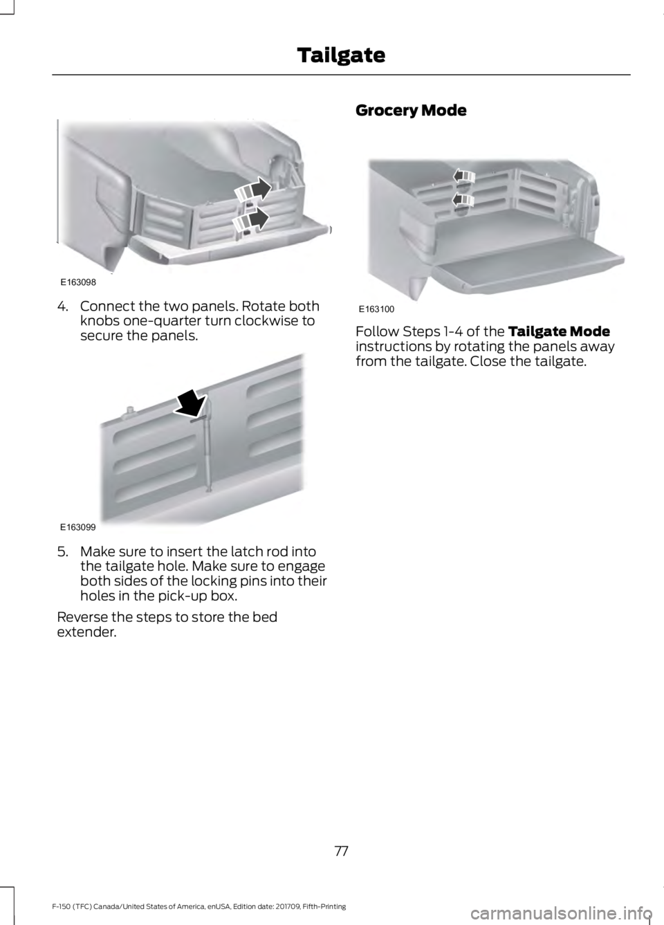
4. Connect the two panels. Rotate both
knobs one-quarter turn clockwise to
secure the panels. 5. Make sure to insert the latch rod into
the tailgate hole. Make sure to engage
both sides of the locking pins into their
holes in the pick-up box.
Reverse the steps to store the bed
extender. Grocery Mode Follow Steps 1-4 of the Tailgate Mode
instructions by rotating the panels away
from the tailgate. Close the tailgate.
77
F-150 (TFC) Canada/United States of America, enUSA, Edition date: 201709, Fifth-Printing TailgateE163098 E163099 E163100
Page 274 of 641
LOAD RETAINING FIXTURES (IF
EQUIPPED)
BoxLink
™ Cleats
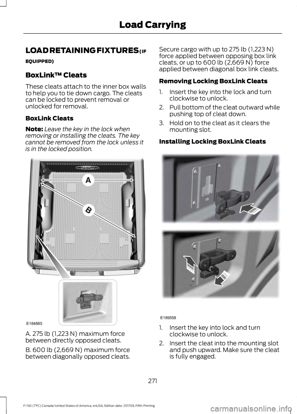
These cleats attach to the inner box walls
to help you to tie down cargo. The cleats
can be locked to prevent removal or
unlocked for removal.
BoxLink Cleats
Note: Leave the key in the lock when
removing or installing the cleats. The key
cannot be removed from the lock unless it
is in the locked position. A. 275 lb (1,223 N) maximum force
between directly opposed cleats.
B. 600 lb (2,669 N)
maximum force
between diagonally opposed cleats. Secure cargo with up to
275 lb (1,223 N)
force applied between opposing box link
cleats, or up to
600 lb (2,669 N) force
applied between diagonal box link cleats.
Removing Locking BoxLink Cleats
1. Insert the key into the lock and turn clockwise to unlock.
2. Pull bottom of the cleat outward while
pushing top of cleat down.
3. Hold on to the cleat as it clears the mounting slot.
Installing Locking BoxLink Cleats 1. Insert the key into lock and turn
clockwise to unlock.
2. Insert the cleat into the mounting slot and push upward. Make sure the cleat
is fully engaged.
271
F-150 (TFC) Canada/United States of America, enUSA, Edition date: 201709, Fifth-Printing Load CarryingE184885 E189558
Page 275 of 641
3. Turn the key counterclockwise to lock.
4. Remove the key.
LOAD LIMIT
Vehicle Loading - with and
without a Trailer
This section guides you in the
proper loading of your vehicle,
trailer, or both. Keep your loaded
vehicle weight within its design
rating capability, with or without
a trailer. Properly loading your
vehicle provides maximum return
of vehicle design performance.
Before you load your vehicle,
become familiar with the
following terms for determining
your vehicle
’s weight rating, with
or without a trailer, from the
vehicle ’s Tire and Loading
Information label or Safety
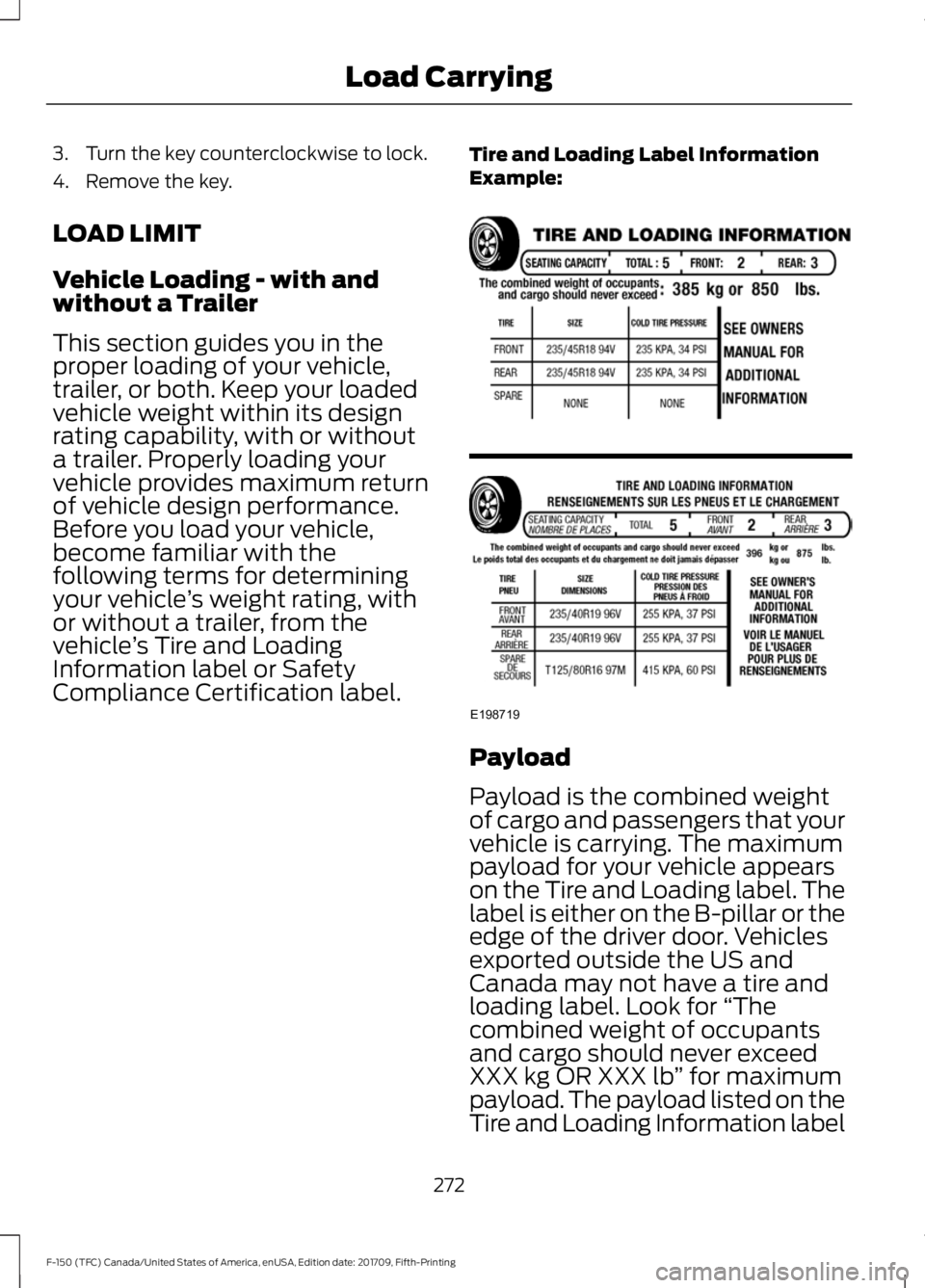
Compliance Certification label. Tire and Loading Label Information
Example:
Payload
Payload is the combined weight
of cargo and passengers that your
vehicle is carrying. The maximum
payload for your vehicle appears
on the Tire and Loading label. The
label is either on the B-pillar or the
edge of the driver door. Vehicles
exported outside the US and
Canada may not have a tire and
loading label. Look for
“The
combined weight of occupants
and cargo should never exceed
XXX kg OR XXX lb ” for maximum
payload. The payload listed on the
Tire and Loading Information label
272
F-150 (TFC) Canada/United States of America, enUSA, Edition date: 201709, Fifth-Printing Load CarryingE198719
Page 290 of 641
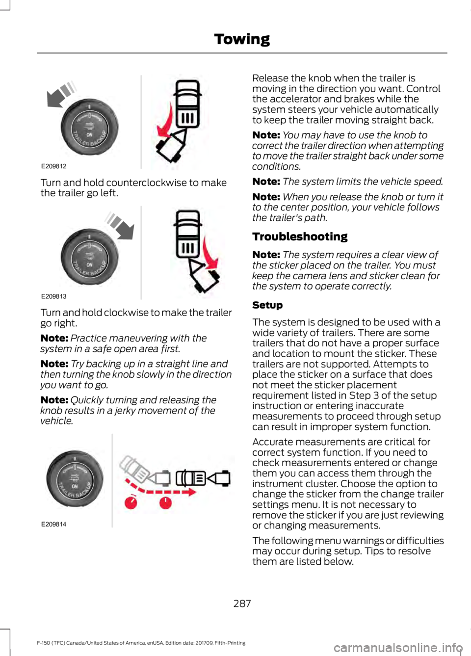
Turn and hold counterclockwise to make
the trailer go left.
Turn and hold clockwise to make the trailer
go right.
Note:
Practice maneuvering with the
system in a safe open area first.
Note: Try backing up in a straight line and
then turning the knob slowly in the direction
you want to go.
Note: Quickly turning and releasing the
knob results in a jerky movement of the
vehicle. Release the knob when the trailer is
moving in the direction you want. Control
the accelerator and brakes while the
system steers your vehicle automatically
to keep the trailer moving straight back.
Note:
You may have to use the knob to
correct the trailer direction when attempting
to move the trailer straight back under some
conditions.
Note: The system limits the vehicle speed.
Note: When you release the knob or turn it
to the center position, your vehicle follows
the trailer's path.
Troubleshooting
Note: The system requires a clear view of
the sticker placed on the trailer. You must
keep the camera lens and sticker clean for
the system to operate correctly.
Setup
The system is designed to be used with a
wide variety of trailers. There are some
trailers that do not have a proper surface
and location to mount the sticker. These
trailers are not supported. Attempts to
place the sticker on a surface that does
not meet the sticker placement
requirement listed in Step 3 of the setup
instruction or entering inaccurate
measurements to proceed through setup
can result in improper system function.
Accurate measurements are critical for
correct system function. If you need to
check measurements entered or change
them you can access them through the
instrument cluster. Choose the option to
change the sticker from the change trailer
settings menu. It is not necessary to
remove the sticker if you are just reviewing
or changing measurements.
The following menu warnings or difficulties
may occur during setup. Tips to resolve
them are listed below.
287
F-150 (TFC) Canada/United States of America, enUSA, Edition date: 201709, Fifth-Printing TowingE209812 E209813 E209814
Page 355 of 641
Only use oils certified for gasoline engines
by the American Petroleum Institute (API).
An oil with this trademark symbol
conforms to the current engine and
emission system protection standards and
fuel economy requirements of the
International Lubricants Specification
Advisory Committee (ILSAC).
To top up the engine oil level do the
following:
1. Clean the area surrounding the engine
oil filler cap before you remove it.
2. Remove the engine oil filler cap. See Under Hood Overview (page 346).
Turn it counterclockwise and remove
it.
3. Add engine oil that meets our specifications. See
Capacities and
Specifications (page 424). You may
have to use a funnel to pour the engine
oil into the opening.
4. Recheck the oil level.
5. If the oil level is correct, replace the dipstick and make sure it is fully seated.
6. Replace the engine oil filler cap. Turn it clockwise until you feel a strong
resistance.
Note: Do not add oil further than the
maximum mark. Oil levels above the
maximum mark may cause engine damage.
Note: Make sure you install the oil filler cap
correctly.
Note: Soak up any spillage with an
absorbent cloth immediately.
ENGINE OIL CHECK - DIESEL
To check the engine oil level consistently
and accurately, do the following:
1. Make sure that your vehicle is on level ground. 2. Run the engine until it reaches normal
operating temperature.
3. Make sure the parking brake is on. Make
sure the transmission is in park (P) or
neutral (N).
4. Switch the engine off and wait 15 minutes for the oil to drain into the oil
pan. Checking the engine oil level too
soon after you switch the engine off
may result in an inaccurate reading.
5. Open the hood. See
Opening and
Closing the Hood (page 345).
6. Remove the dipstick and wipe it with a clean, lint-free cloth. See
Under
Hood Overview (page 346).
7. Replace the dipstick and remove it again to check the oil level. See
Engine Oil Dipstick
(page 350).
8. Make sure that the oil level is between
the maximum and minimum marks. If
the oil level is at the minimum mark,
add oil immediately. See
Capacities
and Specifications (page 424).
9. If the oil level is correct, replace the dipstick and make sure it is fully seated.
Note: Do not remove the dipstick when the
engine is running.
Note: If the oil level is between the
maximum and minimum marks, the oil level
is acceptable. Do not add oil.
Note: The oil consumption of new engines
reaches its normal level after approximately
3,000 mi (5,000 km)
.
Adding Engine Oil WARNING:
Do not remove the
filler cap when the engine is running.
Do not use supplemental engine oil
additives because they are unnecessary
and could lead to engine damage that may
not be covered by the vehicle Warranty.
352
F-150 (TFC) Canada/United States of America, enUSA, Edition date: 201709, Fifth-Printing Maintenance
Page 356 of 641
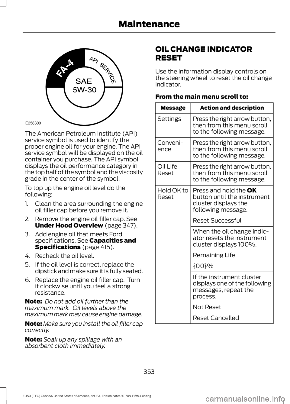
The American Petroleum Institute (API)
service symbol is used to identify the
proper engine oil for your engine. The API
service symbol will be displayed on the oil
container you purchase. The API symbol
displays the oil performance category in
the top half of the symbol and the viscosity
grade in the center of the symbol.
To top up the engine oil level do the
following:
1. Clean the area surrounding the engine
oil filler cap before you remove it.
2. Remove the engine oil filler cap. See
Under Hood Overview (page 347).
3. Add engine oil that meets Ford specifications.
See Capacities and
Specifications (page 415).
4. Recheck the oil level.
5. If the oil level is correct, replace the dipstick and make sure it is fully seated.
6. Replace the engine oil filler cap. Turn it clockwise until you feel a strong
resistance.
Note: Do not add oil further than the
maximum mark. Oil levels above the
maximum mark may cause engine damage.
Note: Make sure you install the oil filler cap
correctly.
Note: Soak up any spillage with an
absorbent cloth immediately. OIL CHANGE INDICATOR
RESET
Use the information display controls on
the steering wheel to reset the oil change
indicator.
From the main menu scroll to:
Action and description
Message
Press the right arrow button,
then from this menu scroll
to the following message.
Settings
Press the right arrow button,
then from this menu scroll
to the following message.
Conveni-
ence
Press the right arrow button,
then from this menu scroll
to the following message.
Oil Life
Reset
Press and hold the
OK
button until the instrument
cluster displays the
following message.
Hold OK to
Reset
Reset Successful
When the oil change indic-
ator resets the instrument
cluster displays 100%.
Remaining Life
{00}%
If the instrument cluster
displays one of the following
messages, repeat the
process.
Not Reset
Reset Cancelled
353
F-150 (TFC) Canada/United States of America, enUSA, Edition date: 201709, Fifth-Printing MaintenanceE258300
Page 358 of 641
It is very important to use prediluted
coolant approved to the correct
specification in order to avoid plugging the
small passageways in the engine cooling
system. See Capacities and
Specifications (page 415). Do not mix
different colors or types of coolant in your
vehicle. Mixing of engine coolants or using
an incorrect coolant may harm the engine
or cooling system components and may
not be covered by the vehicle Warranty.
Note: If prediluted coolant is not available,
use the approved concentrated coolant
diluting it to 50/50 with distilled water. See
Capacities and Specifications (page 415).
Using water that has not been deionised
may contribute to deposit formation,
corrosion and plugging of the small cooling
system passageways.
Note: Coolants marketed for all makes and
models may not be approved to our
specifications and may cause damage to
the cooling system. Resulting component
damage may not be covered by the vehicle
Warranty.
If the coolant level is at or below the
minimum mark, add prediluted coolant
immediately.
To top up the coolant level do the
following:
1. Unscrew the cap slowly. Any pressure escapes as you unscrew the cap.
2. Add prediluted coolant approved to the correct specification. See
Capacities and Specifications (page
415
).
3. Add enough prediluted coolant to reach the correct level.
4. Replace the coolant reservoir cap, turn
it clockwise until you feel a strong
resistance. 5. Check the coolant level in the coolant
reservoir the next few times you drive
your vehicle. If necessary, add enough
prediluted engine coolant to bring the
coolant level to the correct level.
If you have to add more than
1.1 qt (1 L) of
engine coolant per month, have your
vehicle checked as soon as possible.
Operating an engine with a low level of
coolant can result in engine overheating
and possible engine damage.
Note: During normal vehicle operation, the
coolant may change color from orange to
pink or light red. As long as the coolant is
clear and uncontaminated, this color change
does not indicate the coolant has degraded
nor does it require the coolant to be drained,
the system to be flushed, or the coolant to
be replaced.
In case of emergency, you can add a large
amount of water without engine coolant
in order to reach a vehicle service location.
In this instance, qualified personnel:
1. Must drain the cooling system.
2. Chemically clean the coolant system.
3. Refill with engine coolant as soon as possible.
Water alone, without engine coolant, can
cause engine damage from corrosion,
overheating or freezing.
Do not use the following as a coolant
substitute:
• Alcohol.
• Methanol.
• Brine.
• Any coolant mixed with alcohol or
methanol antifreeze.
Alcohol and other liquids can cause engine
damage from overheating or freezing.
355
F-150 (TFC) Canada/United States of America, enUSA, Edition date: 201709, Fifth-Printing Maintenance
Page 364 of 641
WARNING: Keep batteries out of
reach of children. Batteries contain
sulfuric acid. Avoid contact with skin,
eyes or clothing. Shield your eyes when
working near the battery to protect
against possible splashing of acid
solution. In case of acid contact with skin
or eyes, flush immediately with water for
a minimum of 15 minutes and get prompt
medical attention. If acid is swallowed,
call a physician immediately. WARNING:
Battery posts,
terminals and related accessories
contain lead and lead compounds,
chemicals known to the State of
California to cause cancer and
reproductive harm. Wash your hands
after handling
. WARNING: This vehicle may have
more than one battery. Removing the
battery cables from only one battery
does not disconnect your vehicle
electrical system. Make sure you
disconnect the battery cables from all
batteries when disconnecting power.
Failure to do so may cause serious
personal injury or property damage.
Your vehicle is fitted with a Motorcraft
maintenance-free battery which normally
does not require additional water.
When a battery replacement is required,
you must use a recommended
replacement battery that matches the
electrical requirements of the vehicle.
Note: After cleaning or replacing the
battery, make sure you reinstall the battery
cover or shield. Note:
If you add electrical accessories or
components to the vehicle, it may adversely
affect the low voltage battery performance
and durability. This may also affect the
performance of other electrical systems in
the vehicle.
For longer, trouble-free operation, keep the
top of the battery clean and dry.
If you see any corrosion on the battery or
terminals, remove the cables from the
terminals and clean with a wire brush. You
can neutralize the acid with a solution of
baking soda and water.
Because your vehicle ’s engine is
electronically controlled by a computer,
some control conditions are maintained
by power from the battery. When the
battery is disconnected or a new battery
is installed, the engine must relearn its idle
and fuel trim strategy for optimum
driveability and performance. Flexible fuel
vehicles (FFV) must also relearn the
ethanol content of the fuel for optimum
driveability and performance.
To restore the settings, do the following:
1. Apply the parking brake.
2. Shift into park (P) or neutral (N).
3. Switch off all accessories.
4. Press the brake pedal and start your vehicle.
5. Run the engine until it reaches normal operating temperature. While the
engine is warming up, complete the
following: Reset the clock. Reset the
power windows bounce-back feature.
See Windows and Mirrors (page 98).
Reset the radio station presets. See
Audio System
(page 448).
6. Allow the engine to idle for at least one
minute.
7. Drive the vehicle at least 10 mi (16 km)
to completely relearn the idle trim and
fuel trim strategy.
361
F-150 (TFC) Canada/United States of America, enUSA, Edition date: 201709, Fifth-Printing Maintenance
Page 367 of 641
2. Measure the height from the center of
your headlamp (indicated by a 3.0
millimeter circle on the lens) to the
ground and mark an 8 ft (2.4 m)
horizontal reference line on the vertical
wall or screen at this height (a piece of
masking tape works well).
Note: To see a clearer light pattern for
adjusting, you may want to block the light
from one headlamp while adjusting the
other.
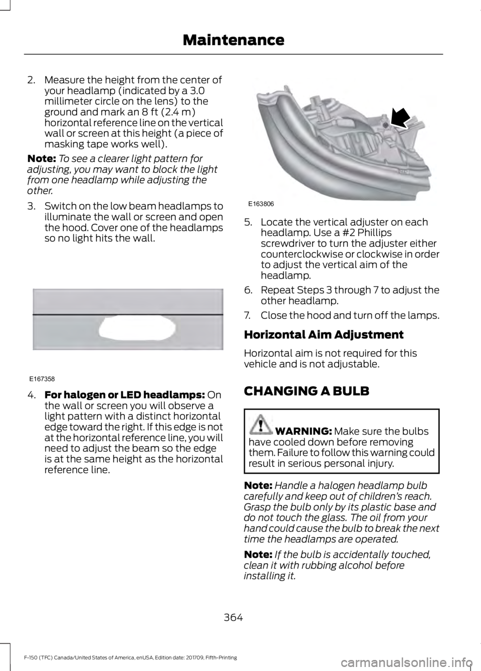
3. Switch on the low beam headlamps to
illuminate the wall or screen and open
the hood. Cover one of the headlamps
so no light hits the wall. 4.
For halogen or LED headlamps:
On
the wall or screen you will observe a
light pattern with a distinct horizontal
edge toward the right. If this edge is not
at the horizontal reference line, you will
need to adjust the beam so the edge
is at the same height as the horizontal
reference line. 5. Locate the vertical adjuster on each
headlamp. Use a #2 Phillips
screwdriver to turn the adjuster either
counterclockwise or clockwise in order
to adjust the vertical aim of the
headlamp.
6. Repeat Steps 3 through 7 to adjust the
other headlamp.
7. Close the hood and turn off the lamps.
Horizontal Aim Adjustment
Horizontal aim is not required for this
vehicle and is not adjustable.
CHANGING A BULB WARNING:
Make sure the bulbs
have cooled down before removing
them. Failure to follow this warning could
result in serious personal injury.
Note: Handle a halogen headlamp bulb
carefully and keep out of children ’s reach.
Grasp the bulb only by its plastic base and
do not touch the glass. The oil from your
hand could cause the bulb to break the next
time the headlamps are operated.
Note: If the bulb is accidentally touched,
clean it with rubbing alcohol before
installing it.
364
F-150 (TFC) Canada/United States of America, enUSA, Edition date: 201709, Fifth-Printing MaintenanceE167358 E163806