sensor FORD F-450 2021 Workshop Manual
[x] Cancel search | Manufacturer: FORD, Model Year: 2021, Model line: F-450, Model: FORD F-450 2021Pages: 666, PDF Size: 11.3 MB
Page 345 of 666
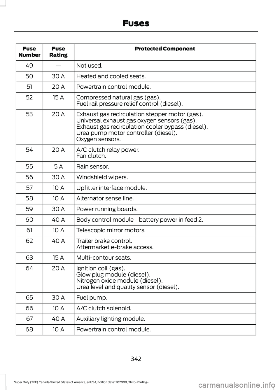
Protected Component
Fuse
Rating
Fuse
Number
Not used.
—
49
Heated and cooled seats.
30 A
50
Powertrain control module.
20 A
51
Compressed natural gas (gas).
15 A
52
Fuel rail pressure relief control (diesel).
Exhaust gas recirculation stepper motor (gas).
20 A
53
Universal exhaust gas oxygen sensors (gas).
Exhaust gas recirculation cooler bypass (diesel).
Urea pump motor controller (diesel).
Oxygen sensors.
A/C clutch relay power.
20 A
54
Fan clutch.
Rain sensor.
5 A
55
Windshield wipers.
30 A
56
Upfitter interface module.
10 A
57
Alternator sense line.
10 A
58
Power running boards.
30 A
59
Body control module - battery power in feed 2.
40 A
60
Telescopic mirror motors.
10 A
61
Trailer brake control.
40 A
62
Aftermarket e-brake access.
Multi-contour seats.
15 A
63
Ignition coil (gas).
20 A
64
Glow plug module (diesel).
Nitrogen oxide module (diesel).
Urea level and quality sensor (diesel).
Fuel pump.
30 A
65
A/C clutch solenoid.
10 A
66
Auxiliary lighting module.
40 A
67
Powertrain control module.
10 A
68
342
Super Duty (TFE) Canada/United States of America, enUSA, Edition date: 202008, Third-Printing- Fuses
Page 347 of 666
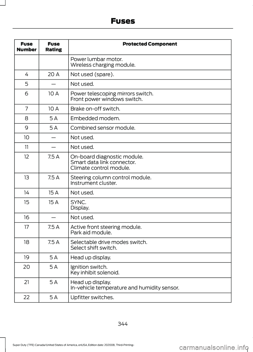
Protected Component
Fuse
Rating
Fuse
Number
Power lumbar motor.
Wireless charging module.
Not used (spare).
20 A
4
Not used.
—
5
Power telescoping mirrors switch.
10 A
6
Front power windows switch.
Brake on-off switch.
10 A
7
Embedded modem.
5 A
8
Combined sensor module.
5 A
9
Not used.
—
10
Not used.
—
11
On-board diagnostic module.
7.5 A
12
Smart data link connector.
Climate control module.
Steering column control module.
7.5 A
13
Instrument cluster.
Not used.
15 A
14
SYNC.
15 A
15
Display.
Not used.
—
16
Active front steering module.
7.5 A
17
Park aid module.
Selectable drive modes switch.
7.5 A
18
Select shift switch.
Head up display.
5 A
19
Ignition switch.
5 A
20
Key inhibit solenoid.
Head up display.
5 A
21
In-vehicle temperature and humidity sensor.
Upfitter switches.
5 A
22
344
Super Duty (TFE) Canada/United States of America, enUSA, Edition date: 202008, Third-Printing- Fuses
Page 360 of 666
From the main menu scroll to:
Action and description
Message
Press the down arrow
button, then from this menu
scroll to the following
message.
Truck Info
Press the OK button.
Mainten-
ance
Monitor
Press the down arrow
button, then from this menu
scroll to the following
message.
Oil Life:
xxx%
Press the
OK button.
Oil Life
Press and hold the
OK
button until the instrument
cluster displays the
following message.
Oil Life
Hold OK to
Reset
Oil Life: 100%
When the oil change indic-
ator resets the instrument
cluster displays 100%.
Repeat the process if the oil
change indicator does not
reset.
CHANGING THE ENGINE AIR
FILTER - 6.2L WARNING:
To reduce the risk of
vehicle damage and personal burn
injuries, do not start your engine with the
air cleaner removed and do not remove
it while the engine is running.
Use the correct specification air filter
element. See
Motorcraft Parts (page
443). Note:
Failure to use the correct air filter
element may result in severe engine
damage. Resulting component damage
may not be covered by the vehicle Warranty.
Change the air filter element at the correct
service interval. See
Scheduled
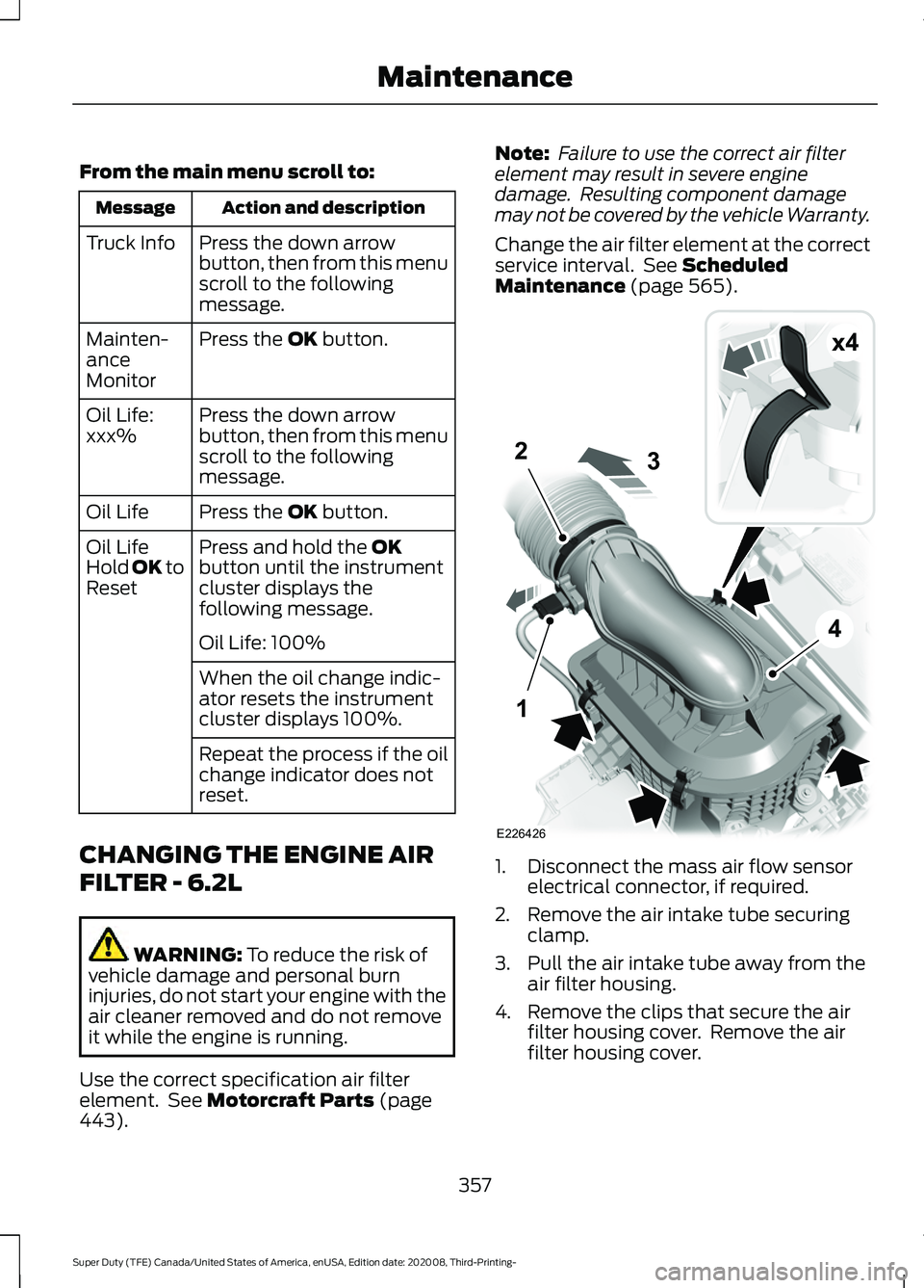
Maintenance (page 565). 1. Disconnect the mass air flow sensor
electrical connector, if required.
2. Remove the air intake tube securing clamp.
3. Pull the air intake tube away from the air filter housing.
4. Remove the clips that secure the air filter housing cover. Remove the air
filter housing cover.
357
Super Duty (TFE) Canada/United States of America, enUSA, Edition date: 202008, Third-Printing- MaintenanceE226426
x4
1
2
4
3
Page 361 of 666
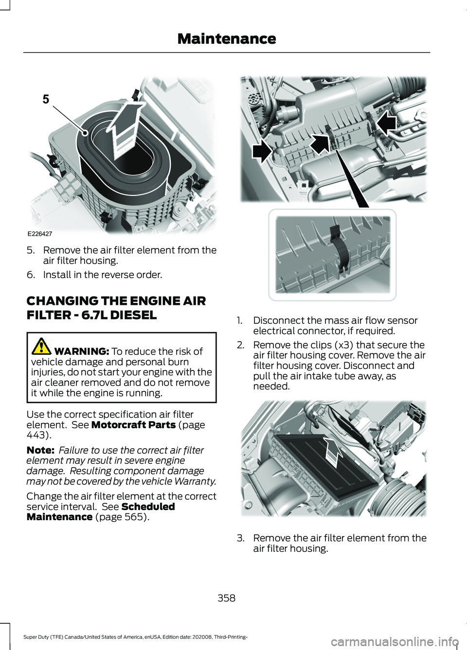
5.
Remove the air filter element from the
air filter housing.
6. Install in the reverse order.
CHANGING THE ENGINE AIR
FILTER - 6.7L DIESEL WARNING: To reduce the risk of
vehicle damage and personal burn
injuries, do not start your engine with the
air cleaner removed and do not remove
it while the engine is running.
Use the correct specification air filter
element. See
Motorcraft Parts (page
443).
Note: Failure to use the correct air filter
element may result in severe engine
damage. Resulting component damage
may not be covered by the vehicle Warranty.
Change the air filter element at the correct
service interval. See
Scheduled
Maintenance (page 565). 1. Disconnect the mass air flow sensor
electrical connector, if required.
2. Remove the clips (x3) that secure the air filter housing cover. Remove the air
filter housing cover. Disconnect and
pull the air intake tube away, as
needed. 3.
Remove the air filter element from the
air filter housing.
358
Super Duty (TFE) Canada/United States of America, enUSA, Edition date: 202008, Third-Printing- MaintenanceE226427
5 E310318 E310319
Page 363 of 666
CHANGING THE ENGINE AIR
FILTER - 7.3L
WARNING: To reduce the risk of
vehicle damage and personal burn
injuries, do not start your engine with the
air cleaner removed and do not remove
it while the engine is running.
Note: Operating your vehicle in heavy
snowfall or extreme rain conditions may
allow excessive amounts of snow or water
into the air intake system. This could plug
or soak the air filter that could cause the
engine to lose power or shut down.
When replacing the air filter element, use
a Motorcraft® air filter element. See
Motorcraft Parts
(page 443).
Note: Failure to use the correct air filter
element may result in severe engine
damage. Resulting component damage
may not be covered by the vehicle Warranty.
Change the air filter element at the correct
interval. See
Scheduled Maintenance
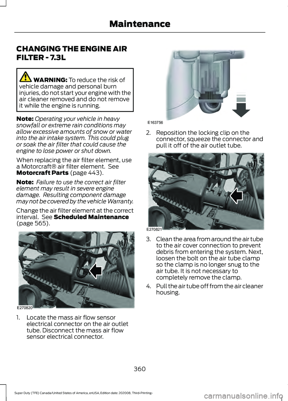
(page 565). 1. Locate the mass air flow sensor
electrical connector on the air outlet
tube. Disconnect the mass air flow
sensor electrical connector. 2. Reposition the locking clip on the
connector, squeeze the connector and
pull it off of the air outlet tube. 3.
Clean the area from around the air tube
to the air cover connection to prevent
debris from entering the system. Next,
loosen the bolt on the air tube clamp
so the clamp is no longer snug to the
air tube. It is not necessary to
completely remove the clamp.
4. Pull the air tube off from the air cleaner
housing.
360
Super Duty (TFE) Canada/United States of America, enUSA, Edition date: 202008, Third-Printing- MaintenanceE270820 E163756 E270821
Page 364 of 666
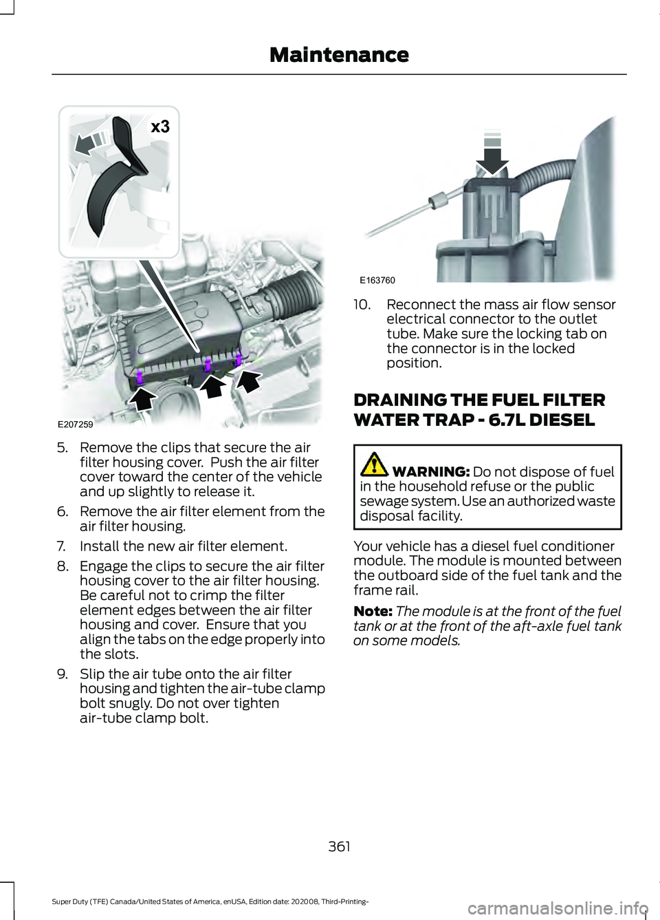
5. Remove the clips that secure the air
filter housing cover. Push the air filter
cover toward the center of the vehicle
and up slightly to release it.
6. Remove the air filter element from the
air filter housing.
7. Install the new air filter element.
8. Engage the clips to secure the air filter housing cover to the air filter housing.
Be careful not to crimp the filter
element edges between the air filter
housing and cover. Ensure that you
align the tabs on the edge properly into
the slots.
9. Slip the air tube onto the air filter housing and tighten the air-tube clamp
bolt snugly. Do not over tighten
air-tube clamp bolt. 10. Reconnect the mass air flow sensor
electrical connector to the outlet
tube. Make sure the locking tab on
the connector is in the locked
position.
DRAINING THE FUEL FILTER
WATER TRAP - 6.7L DIESEL WARNING: Do not dispose of fuel
in the household refuse or the public
sewage system. Use an authorized waste
disposal facility.
Your vehicle has a diesel fuel conditioner
module. The module is mounted between
the outboard side of the fuel tank and the
frame rail.
Note: The module is at the front of the fuel
tank or at the front of the aft-axle fuel tank
on some models.
361
Super Duty (TFE) Canada/United States of America, enUSA, Edition date: 202008, Third-Printing- MaintenanceE207259
x3 E163760
Page 420 of 666
WARNING: To reduce the
risk of serious injury, when
mounting replacement tires and
wheels, you should not exceed
the maximum pressure indicated
on the sidewall of the tire to set
the beads without additional
precautions listed below. If the
beads do not seat at the
maximum pressure indicated,
re-lubricate and try again.
When inflating the tire for
mounting pressures up to 20 psi
(1.38 bar)
greater than the
maximum pressure on the tire
sidewall, the following
precautions must be taken to
protect the person mounting the
tire:
1. Make sure that you have the
correct tire and wheel size.
2. Lubricate the tire bead and
wheel bead seat area again.
3. Stand at a minimum of
12 ft
(3.66 m) away from the wheel
and tire assembly.
4. Use both eye and ear
protection. WARNING: For a mounting
pressure more than
20 psi
(1.38 bar) greater than the
maximum pressure, a Ford
dealer or other tire service
professional should do the
mounting. WARNING:
Always inflate
steel carcass tires with a remote
air fill with the person inflating
standing at a minimum of
12 ft
(3.66 m) away from the wheel
and tire assembly.
Important: Remember to replace
the wheel valve stems when the
road tires are replaced on your
vehicle.
The two front tires or two rear tires
should generally be replaced as a
pair.
The tire pressure sensors mounted
in the wheels are not designed to
be used in aftermarket wheels.
The use of wheels or tires not
recommended by Ford Motor
Company may affect the
operation of your tire pressure
monitoring system.
If the tire pressure monitoring
system indicator is flashing, the
system is malfunctioning. Your
replacement tire might be
incompatible with your tire
pressure monitoring system, or
some component of the system
may be damaged.
417
Super Duty (TFE) Canada/United States of America, enUSA, Edition date: 202008, Third-Printing- Wheels and Tires
Page 422 of 666
Wheel misalignment in the front
or the rear can cause uneven and
rapid treadwear of your tires and
should be corrected by an
authorized dealer. Front-wheel
drive vehicles and those with an
independent rear suspension may
require alignment of all four
wheels.
The tires should also be balanced
periodically. An unbalanced tire
and wheel assembly may result in
irregular tire wear.
Tire Rotation
WARNING: If the tire label
shows different tire pressures for
the front and rear tires and the
vehicle has a tire pressure
monitoring system, then you
need to update the settings for
the system sensors. Always
perform the system reset
procedure after tire rotation. If
you do not reset the system, it
may not provide a low tire
pressure warning when
necessary.
Note: If your tires show uneven
wear ask an authorized dealer to
check for and correct any wheel
misalignment, tire imbalance or
mechanical problem involved
before tire rotation. Note:
Your vehicle may be
equipped with a dissimilar spare
wheel and tire assembly. A
dissimilar spare wheel and tire
assembly is defined as a spare
wheel and tire assembly that is
different in brand, size or
appearance from the road tires and
wheels. If you have a dissimilar
spare wheel and tire assembly it is
intended for temporary use only
and should not be used in a tire
rotation.
Note: After having your tires
rotated, inflation pressure must be
checked and adjusted to the
vehicle requirements.
Rotating your tires at the
recommended interval (as
indicated in the Scheduled
Maintenance chapter) will help
your tires wear more evenly,
providing better tire performance
and longer tire life. Sometime
irregular tire wear can be
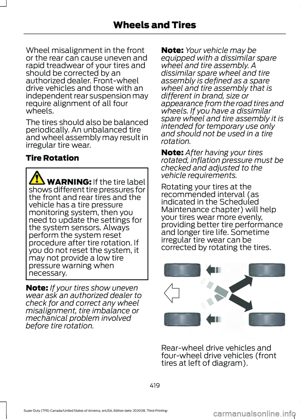
corrected by rotating the tires. Rear-wheel drive vehicles and
four-wheel drive vehicles (front
tires at left of diagram).
419
Super Duty (TFE) Canada/United States of America, enUSA, Edition date: 202008, Third-Printing- Wheels and TiresE142548
Page 426 of 666
Note:
Each road tire is equipped with a tire
pressure sensor located inside the wheel
and tire assembly cavity. The pressure
sensor is attached to the valve stem. The
pressure sensor is covered by the tire and is
not visible unless the tire is removed. Take
care when changing the tire to avoid
damaging the sensor.
You should always have your tires serviced
by an authorized dealer.
Periodically check the tire pressure, at least
monthly, using an accurate tire gauge. See
Inflating Your Tires in this chapter.
Understanding Your Tire Pressure
Monitoring System
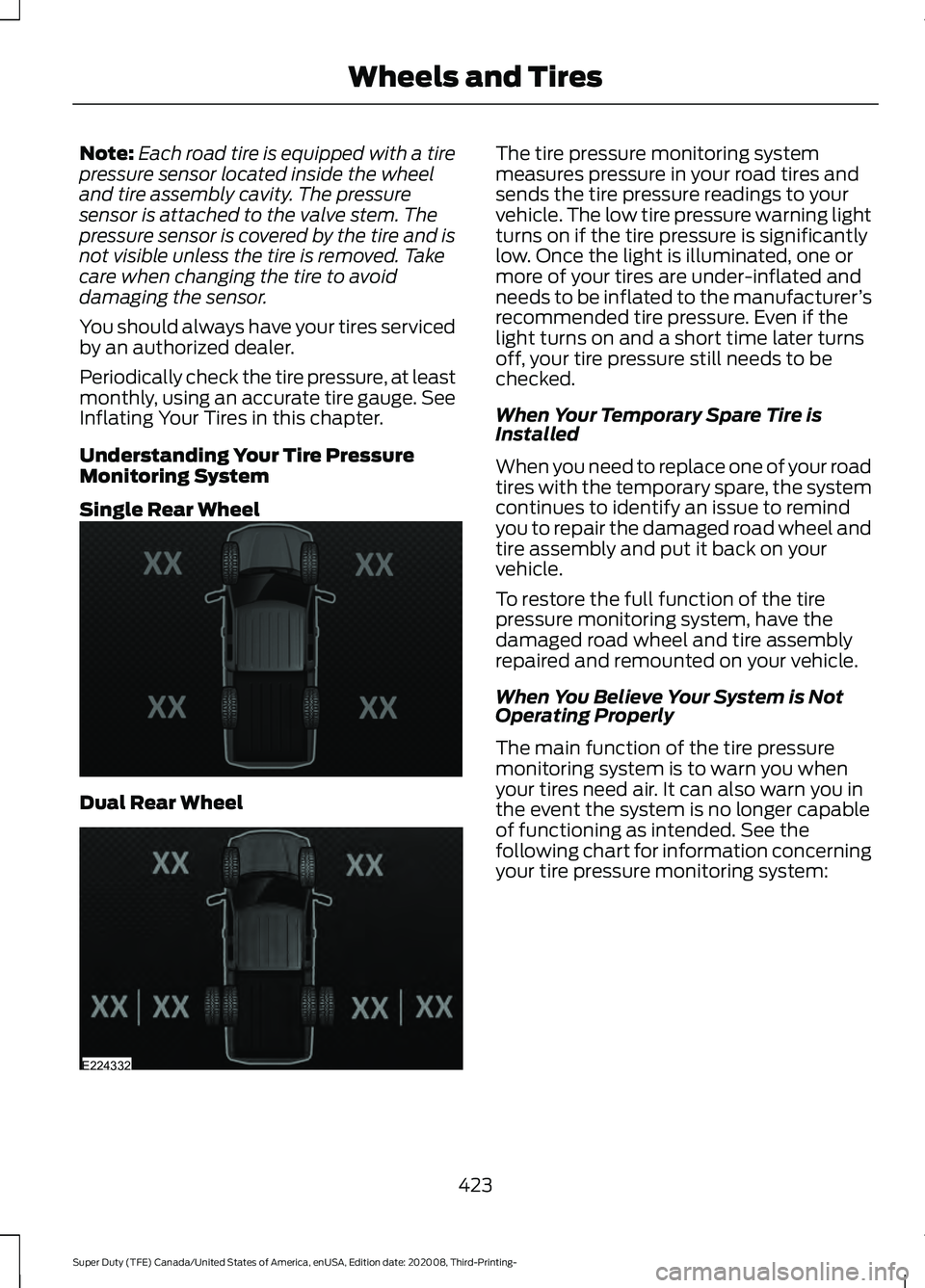
Single Rear Wheel Dual Rear Wheel The tire pressure monitoring system
measures pressure in your road tires and
sends the tire pressure readings to your
vehicle. The low tire pressure warning light
turns on if the tire pressure is significantly
low. Once the light is illuminated, one or
more of your tires are under-inflated and
needs to be inflated to the manufacturer
’s
recommended tire pressure. Even if the
light turns on and a short time later turns
off, your tire pressure still needs to be
checked.
When Your Temporary Spare Tire is
Installed
When you need to replace one of your road
tires with the temporary spare, the system
continues to identify an issue to remind
you to repair the damaged road wheel and
tire assembly and put it back on your
vehicle.
To restore the full function of the tire
pressure monitoring system, have the
damaged road wheel and tire assembly
repaired and remounted on your vehicle.
When You Believe Your System is Not
Operating Properly
The main function of the tire pressure
monitoring system is to warn you when
your tires need air. It can also warn you in
the event the system is no longer capable
of functioning as intended. See the
following chart for information concerning
your tire pressure monitoring system:
423
Super Duty (TFE) Canada/United States of America, enUSA, Edition date: 202008, Third-Printing- Wheels and TiresE224333 E224332
Page 427 of 666
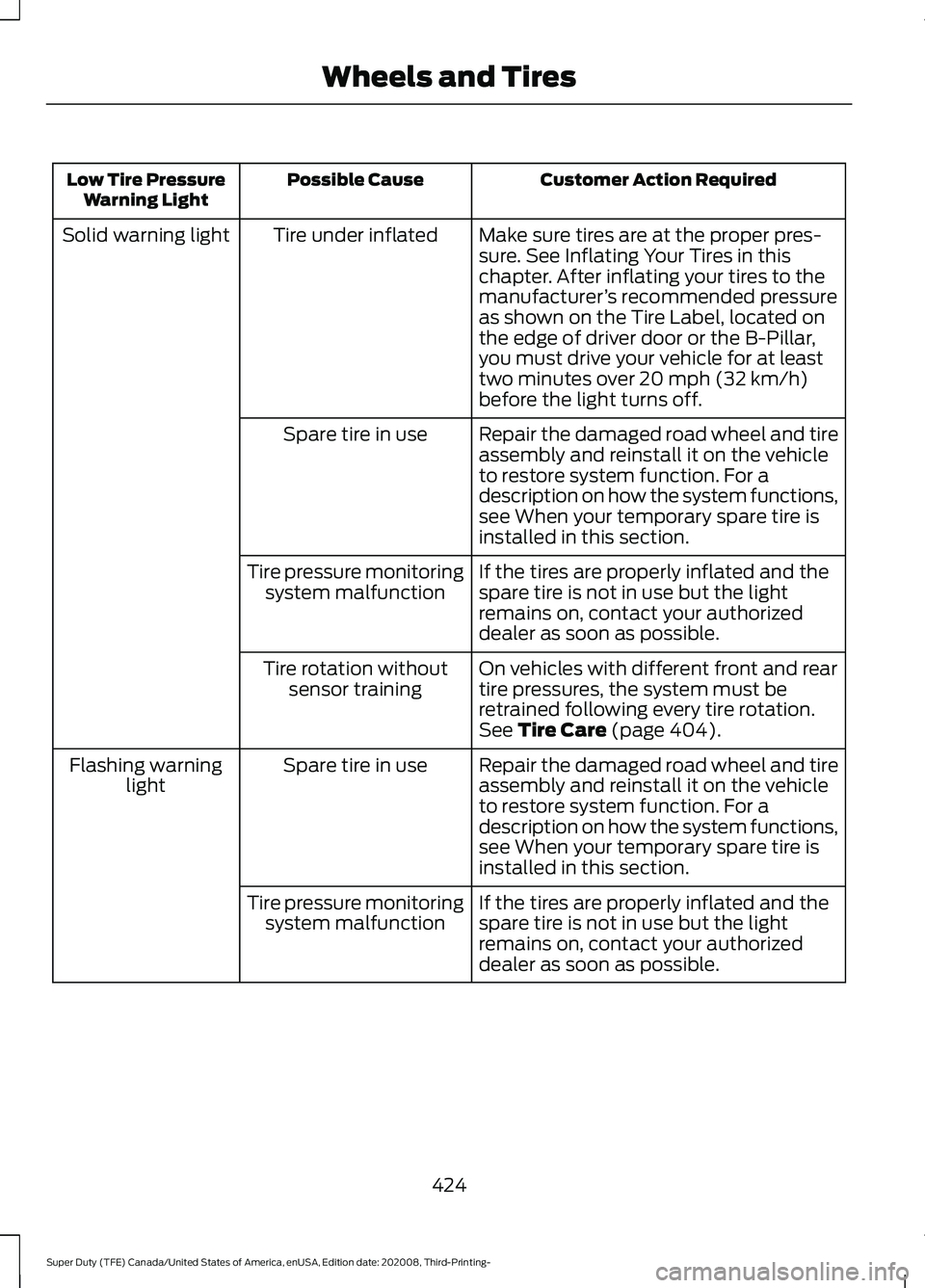
Customer Action Required
Possible Cause
Low Tire Pressure
Warning Light
Make sure tires are at the proper pres-
sure. See Inflating Your Tires in this
chapter. After inflating your tires to the
manufacturer’s recommended pressure
as shown on the Tire Label, located on
the edge of driver door or the B-Pillar,
you must drive your vehicle for at least
two minutes over 20 mph (32 km/h)
before the light turns off.
Tire under inflated
Solid warning light
Repair the damaged road wheel and tire
assembly and reinstall it on the vehicle
to restore system function. For a
description on how the system functions,
see When your temporary spare tire is
installed in this section.
Spare tire in use
If the tires are properly inflated and the
spare tire is not in use but the light
remains on, contact your authorized
dealer as soon as possible.
Tire pressure monitoring
system malfunction
On vehicles with different front and rear
tire pressures, the system must be
retrained following every tire rotation.
See
Tire Care (page 404).
Tire rotation without
sensor training
Repair the damaged road wheel and tire
assembly and reinstall it on the vehicle
to restore system function. For a
description on how the system functions,
see When your temporary spare tire is
installed in this section.
Spare tire in use
Flashing warning
light
If the tires are properly inflated and the
spare tire is not in use but the light
remains on, contact your authorized
dealer as soon as possible.
Tire pressure monitoring
system malfunction
424
Super Duty (TFE) Canada/United States of America, enUSA, Edition date: 202008, Third-Printing- Wheels and Tires