clock FORD F-600 2022 Owner's Manual
[x] Cancel search | Manufacturer: FORD, Model Year: 2022, Model line: F-600, Model: FORD F-600 2022Pages: 740, PDF Size: 12.6 MB
Page 419 of 740
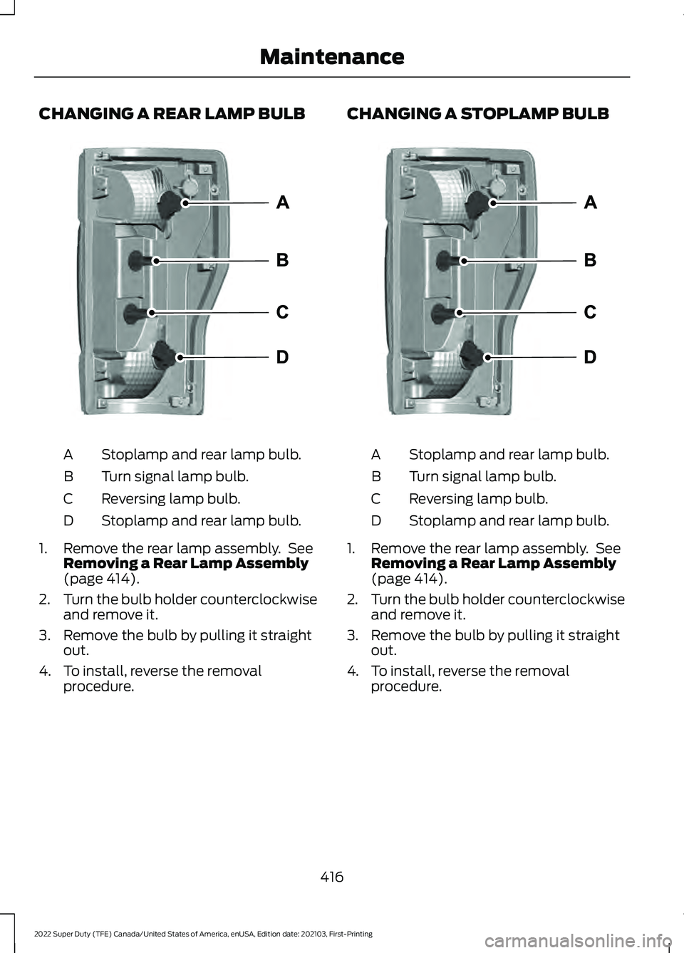
CHANGING A REAR LAMP BULB
Stoplamp and rear lamp bulb.
A
Turn signal lamp bulb.
B
Reversing lamp bulb.
C
Stoplamp and rear lamp bulb.
D
1. Remove the rear lamp assembly. See Removing a Rear Lamp Assembly
(page 414).
2. Turn the bulb holder counterclockwise
and remove it.
3. Remove the bulb by pulling it straight out.
4. To install, reverse the removal procedure. CHANGING A STOPLAMP BULB
Stoplamp and rear lamp bulb.
A
Turn signal lamp bulb.
B
Reversing lamp bulb.
C
Stoplamp and rear lamp bulb.
D
1. Remove the rear lamp assembly. See Removing a Rear Lamp Assembly
(page 414).
2. Turn the bulb holder counterclockwise
and remove it.
3. Remove the bulb by pulling it straight out.
4. To install, reverse the removal procedure.
416
2022 Super Duty (TFE) Canada/United States of America, enUSA, Edition date: 202103, First-Printing MaintenanceE346947 E346947
Page 420 of 740
CHANGING A REAR TURN SIGNAL
LAMP BULB
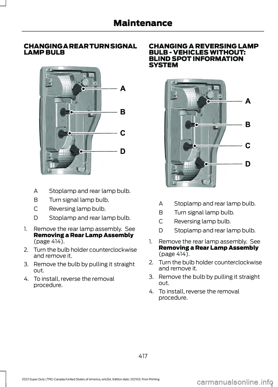
Stoplamp and rear lamp bulb.
A
Turn signal lamp bulb.
B
Reversing lamp bulb.
C
Stoplamp and rear lamp bulb.
D
1. Remove the rear lamp assembly. See Removing a Rear Lamp Assembly
(page 414).
2. Turn the bulb holder counterclockwise
and remove it.
3. Remove the bulb by pulling it straight out.
4. To install, reverse the removal procedure. CHANGING A REVERSING LAMP
BULB - VEHICLES WITHOUT:
BLIND SPOT INFORMATION
SYSTEM
Stoplamp and rear lamp bulb.
A
Turn signal lamp bulb.
B
Reversing lamp bulb.
C
Stoplamp and rear lamp bulb.
D
1. Remove the rear lamp assembly. See Removing a Rear Lamp Assembly
(page
414).
2. Turn the bulb holder counterclockwise
and remove it.
3. Remove the bulb by pulling it straight out.
4. To install, reverse the removal procedure.
417
2022 Super Duty (TFE) Canada/United States of America, enUSA, Edition date: 202103, First-Printing MaintenanceE346947 E346947
Page 421 of 740
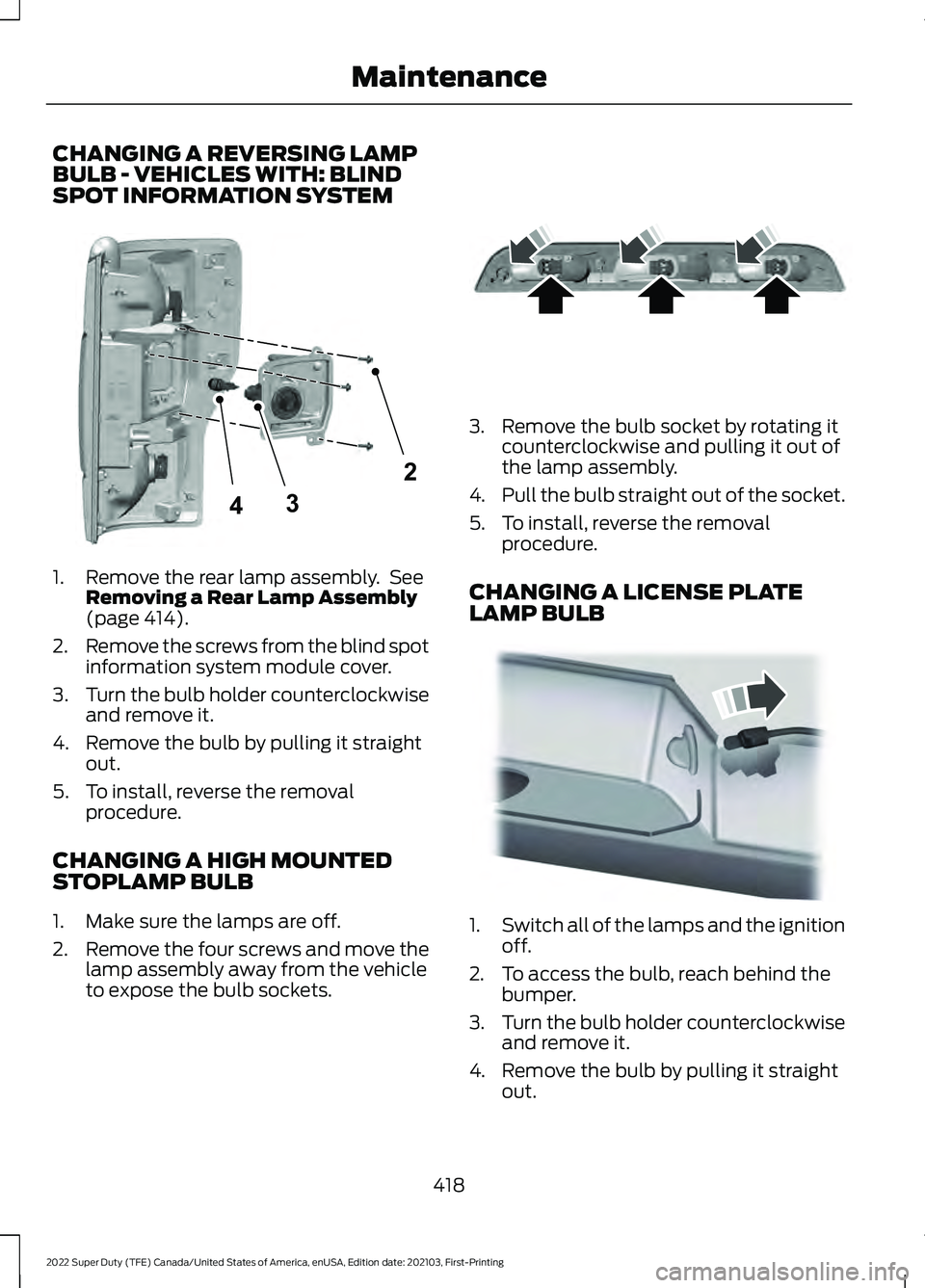
CHANGING A REVERSING LAMP
BULB - VEHICLES WITH: BLIND
SPOT INFORMATION SYSTEM
1. Remove the rear lamp assembly. See
Removing a Rear Lamp Assembly
(page 414).
2. Remove the screws from the blind spot
information system module cover.
3. Turn the bulb holder counterclockwise
and remove it.
4. Remove the bulb by pulling it straight out.
5. To install, reverse the removal procedure.
CHANGING A HIGH MOUNTED
STOPLAMP BULB
1. Make sure the lamps are off.
2. Remove the four screws and move the
lamp assembly away from the vehicle
to expose the bulb sockets. 3. Remove the bulb socket by rotating it
counterclockwise and pulling it out of
the lamp assembly.
4. Pull the bulb straight out of the socket.
5. To install, reverse the removal procedure.
CHANGING A LICENSE PLATE
LAMP BULB 1.
Switch all of the lamps and the ignition
off.
2. To access the bulb, reach behind the bumper.
3. Turn the bulb holder counterclockwise
and remove it.
4. Remove the bulb by pulling it straight out.
418
2022 Super Duty (TFE) Canada/United States of America, enUSA, Edition date: 202103, First-Printing Maintenance2
34E346930 E187290 E163830
Page 460 of 740
WARNING: To help prevent your
vehicle from moving when changing a
wheel, shift the transmission into park
(P), set the parking brake and use an
appropriate block or wheel chock to
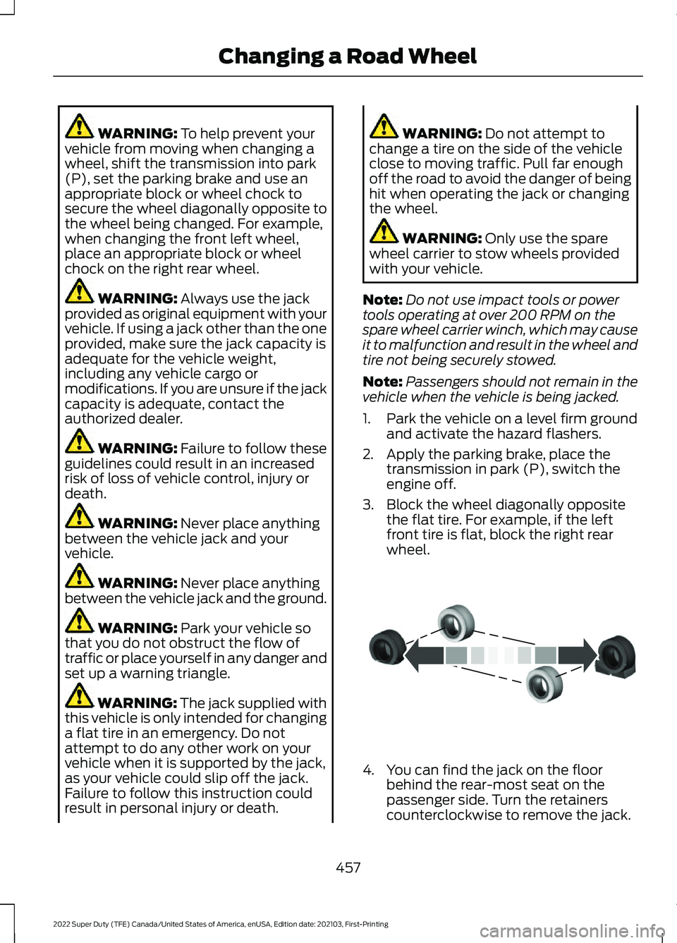
secure the wheel diagonally opposite to
the wheel being changed. For example,
when changing the front left wheel,
place an appropriate block or wheel
chock on the right rear wheel. WARNING:
Always use the jack
provided as original equipment with your
vehicle. If using a jack other than the one
provided, make sure the jack capacity is
adequate for the vehicle weight,
including any vehicle cargo or
modifications. If you are unsure if the jack
capacity is adequate, contact the
authorized dealer. WARNING:
Failure to follow these
guidelines could result in an increased
risk of loss of vehicle control, injury or
death. WARNING:
Never place anything
between the vehicle jack and your
vehicle. WARNING:
Never place anything
between the vehicle jack and the ground. WARNING:
Park your vehicle so
that you do not obstruct the flow of
traffic or place yourself in any danger and
set up a warning triangle. WARNING:
The jack supplied with
this vehicle is only intended for changing
a flat tire in an emergency. Do not
attempt to do any other work on your
vehicle when it is supported by the jack,
as your vehicle could slip off the jack.
Failure to follow this instruction could
result in personal injury or death. WARNING:
Do not attempt to
change a tire on the side of the vehicle
close to moving traffic. Pull far enough
off the road to avoid the danger of being
hit when operating the jack or changing
the wheel. WARNING:
Only use the spare
wheel carrier to stow wheels provided
with your vehicle.
Note: Do not use impact tools or power
tools operating at over 200 RPM on the
spare wheel carrier winch, which may cause
it to malfunction and result in the wheel and
tire not being securely stowed.
Note: Passengers should not remain in the
vehicle when the vehicle is being jacked.
1. Park the vehicle on a level firm ground and activate the hazard flashers.
2. Apply the parking brake, place the transmission in park (P), switch the
engine off.
3. Block the wheel diagonally opposite the flat tire. For example, if the left
front tire is flat, block the right rear
wheel. 4. You can find the jack on the floor
behind the rear-most seat on the
passenger side. Turn the retainers
counterclockwise to remove the jack.
457
2022 Super Duty (TFE) Canada/United States of America, enUSA, Edition date: 202103, First-Printing Changing a Road WheelE175447
Page 461 of 740
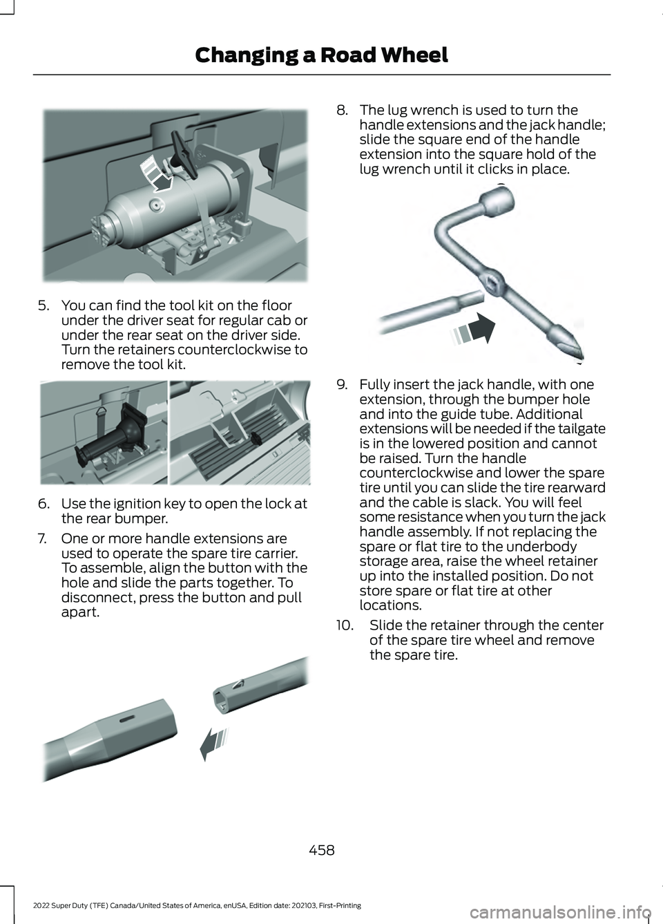
5. You can find the tool kit on the floor
under the driver seat for regular cab or
under the rear seat on the driver side.
Turn the retainers counterclockwise to
remove the tool kit. 6.
Use the ignition key to open the lock at
the rear bumper.
7. One or more handle extensions are used to operate the spare tire carrier.
To assemble, align the button with the
hole and slide the parts together. To
disconnect, press the button and pull
apart. 8. The lug wrench is used to turn the
handle extensions and the jack handle;
slide the square end of the handle
extension into the square hold of the
lug wrench until it clicks in place. 9. Fully insert the jack handle, with one
extension, through the bumper hole
and into the guide tube. Additional
extensions will be needed if the tailgate
is in the lowered position and cannot
be raised. Turn the handle
counterclockwise and lower the spare
tire until you can slide the tire rearward
and the cable is slack. You will feel
some resistance when you turn the jack
handle assembly. If not replacing the
spare or flat tire to the underbody
storage area, raise the wheel retainer
up into the installed position. Do not
store spare or flat tire at other
locations.
10. Slide the retainer through the center of the spare tire wheel and remove
the spare tire.
458
2022 Super Duty (TFE) Canada/United States of America, enUSA, Edition date: 202103, First-Printing Changing a Road WheelE309424 E309795 E308882 E162796
Page 462 of 740
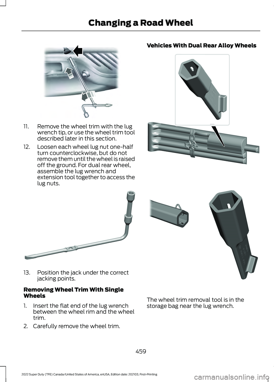
11. Remove the wheel trim with the lug
wrench tip, or use the wheel trim tool
described later in this section.
12. Loosen each wheel lug nut one-half turn counterclockwise, but do not
remove them until the wheel is raised
off the ground. For dual rear wheel,
assemble the lug wrench and
extension tool together to access the
lug nuts. 13. Position the jack under the correct
jacking points.
Removing Wheel Trim With Single
Wheels
1. Insert the flat end of the lug wrench between the wheel rim and the wheel
trim.
2. Carefully remove the wheel trim. Vehicles With Dual Rear Alloy Wheels
The wheel trim removal tool is in the
storage bag near the lug wrench.
459
2022 Super Duty (TFE) Canada/United States of America, enUSA, Edition date: 202103, First-Printing Changing a Road WheelE310417 E309794 E338541 E338539
Page 465 of 740
Note:
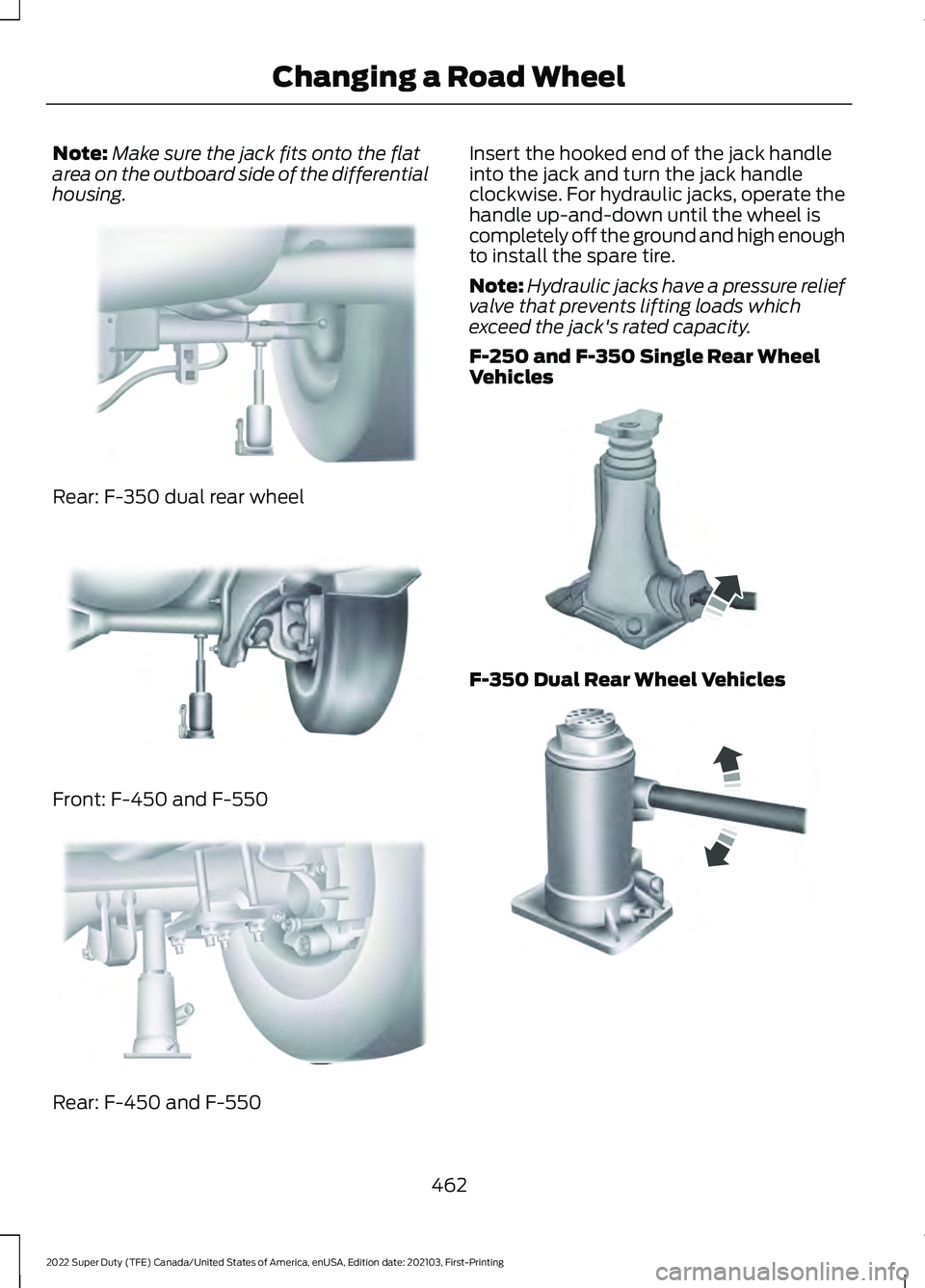
Make sure the jack fits onto the flat
area on the outboard side of the differential
housing. Rear: F-350 dual rear wheel
Front: F-450 and F-550
Rear: F-450 and F-550 Insert the hooked end of the jack handle
into the jack and turn the jack handle
clockwise. For hydraulic jacks, operate the
handle up-and-down until the wheel is
completely off the ground and high enough
to install the spare tire.
Note:
Hydraulic jacks have a pressure relief
valve that prevents lifting loads which
exceed the jack's rated capacity.
F-250 and F-350 Single Rear Wheel
Vehicles F-350 Dual Rear Wheel Vehicles
462
2022 Super Duty (TFE) Canada/United States of America, enUSA, Edition date: 202103, First-Printing Changing a Road WheelE162817 E162816 E162818 E162811 E162819
Page 466 of 740
Remove the lug nuts with the lug wrench,
replace the flat tire with the spare, making
sure the valve stem of the spare is facing
outward when replacing a front wheel. For
the rear wheel position on vehicles with
single rear wheel fitments, install the spare
with the valve stem facing outward. For
vehicles with dual rear wheels, the valve
stem of the spare must face outward when
replacing an inner wheel, but must face
inward when replacing an outboard wheel.
Reinstall the lug nuts until the wheel is
snug against the hub. Do not fully tighten
the lug nuts until the wheel has been
lowered.
Lower the vehicle completely by turning
the jack handle counterclockwise until the
vehicle is completely lowered.
Note:
For F-350 Dual Rear Wheel, F-450
and F-550 Vehicles, insert the notched end
of the jack handle to the release valve, open
the release valve slightly by turning the
handle counterclockwise. Stop turning the
release valve when vehicle start to lower.
Make sure to close the valve when you
completely lower your vehicle.
F-350 Dual Rear Wheel, F-450 and
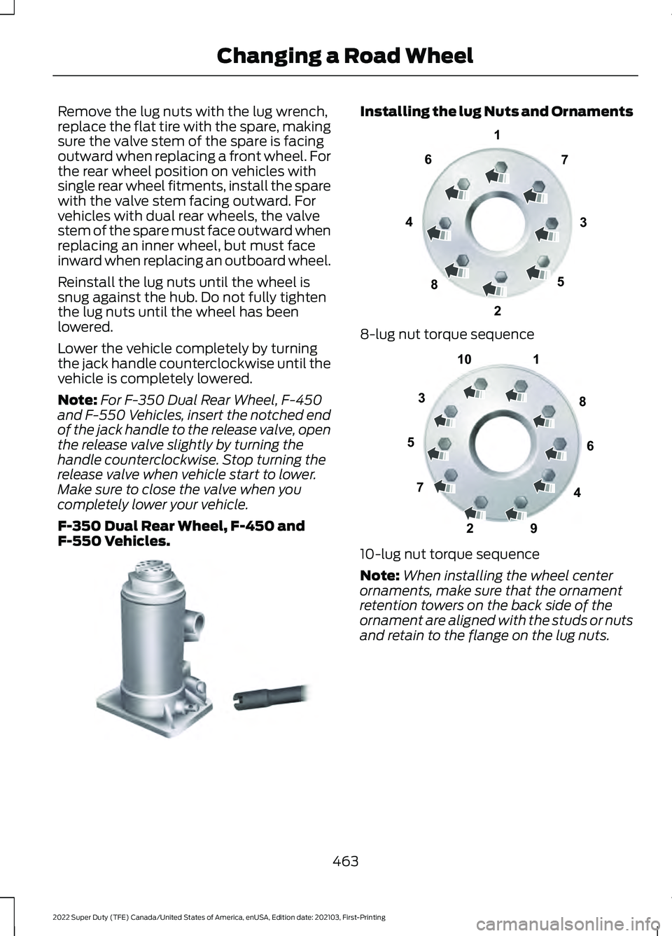
F-550 Vehicles. Installing the lug Nuts and Ornaments
8-lug nut torque sequence
10-lug nut torque sequence
Note:
When installing the wheel center
ornaments, make sure that the ornament
retention towers on the back side of the
ornament are aligned with the studs or nuts
and retain to the flange on the lug nuts.
463
2022 Super Duty (TFE) Canada/United States of America, enUSA, Edition date: 202103, First-Printing Changing a Road WheelE162812 13
4
27
6
5
8E161441 1
2
3
4
5
6
7 8
9
10E169375
Page 468 of 740
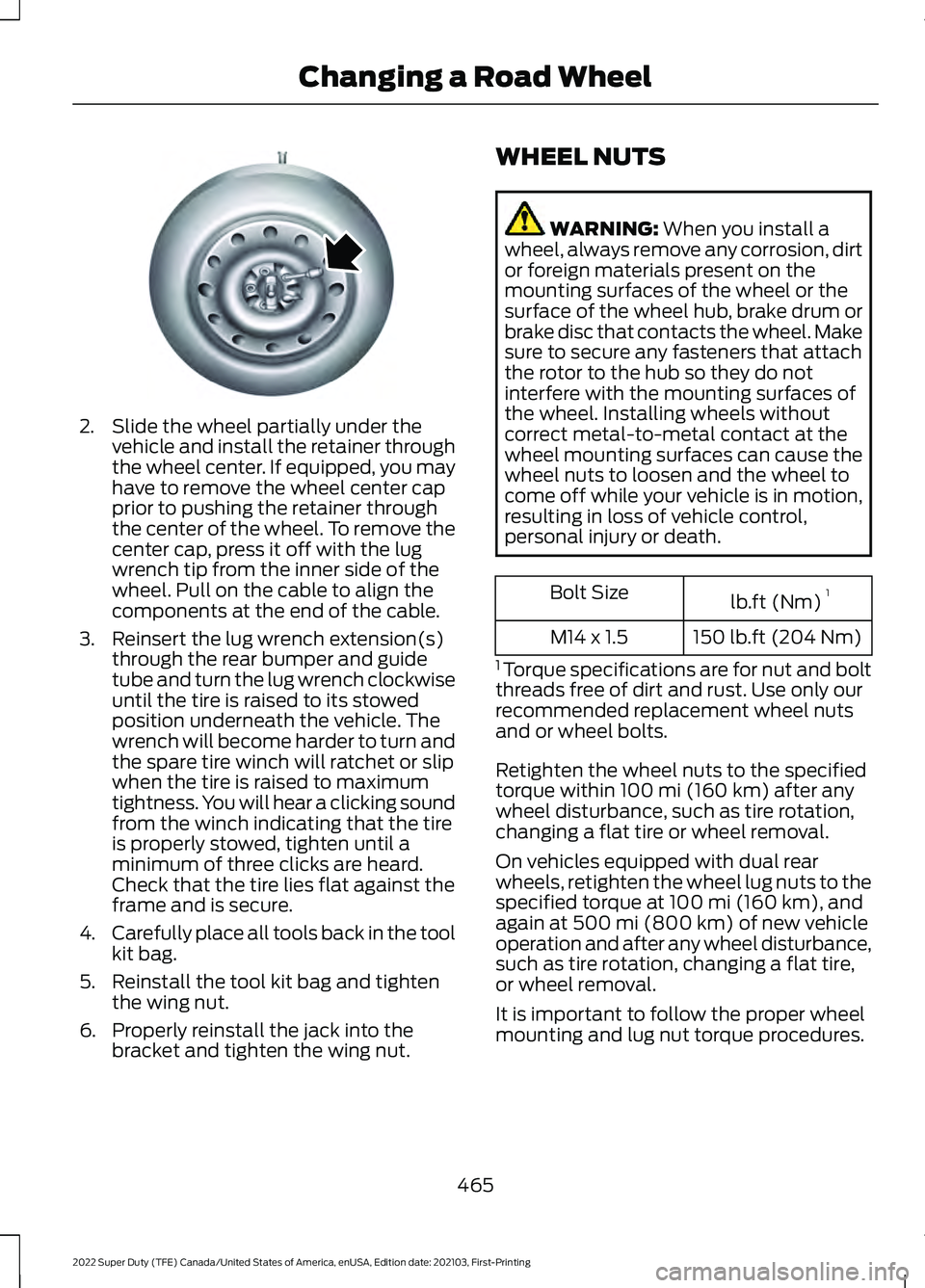
2. Slide the wheel partially under the
vehicle and install the retainer through
the wheel center. If equipped, you may
have to remove the wheel center cap
prior to pushing the retainer through
the center of the wheel. To remove the
center cap, press it off with the lug
wrench tip from the inner side of the
wheel. Pull on the cable to align the
components at the end of the cable.
3. Reinsert the lug wrench extension(s) through the rear bumper and guide
tube and turn the lug wrench clockwise
until the tire is raised to its stowed
position underneath the vehicle. The
wrench will become harder to turn and
the spare tire winch will ratchet or slip
when the tire is raised to maximum
tightness. You will hear a clicking sound
from the winch indicating that the tire
is properly stowed, tighten until a
minimum of three clicks are heard.
Check that the tire lies flat against the
frame and is secure.
4. Carefully place all tools back in the tool
kit bag.
5. Reinstall the tool kit bag and tighten the wing nut.
6. Properly reinstall the jack into the bracket and tighten the wing nut. WHEEL NUTS WARNING: When you install a
wheel, always remove any corrosion, dirt
or foreign materials present on the
mounting surfaces of the wheel or the
surface of the wheel hub, brake drum or
brake disc that contacts the wheel. Make
sure to secure any fasteners that attach
the rotor to the hub so they do not
interfere with the mounting surfaces of
the wheel. Installing wheels without
correct metal-to-metal contact at the
wheel mounting surfaces can cause the
wheel nuts to loosen and the wheel to
come off while your vehicle is in motion,
resulting in loss of vehicle control,
personal injury or death. lb.ft (Nm)
1
Bolt Size
150 lb.ft (204 Nm)
M14 x 1.5
1 Torque specifications are for nut and bolt
threads free of dirt and rust. Use only our
recommended replacement wheel nuts
and or wheel bolts.
Retighten the wheel nuts to the specified
torque within
100 mi (160 km) after any
wheel disturbance, such as tire rotation,
changing a flat tire or wheel removal.
On vehicles equipped with dual rear
wheels, retighten the wheel lug nuts to the
specified torque at
100 mi (160 km), and
again at 500 mi (800 km) of new vehicle
operation and after any wheel disturbance,
such as tire rotation, changing a flat tire,
or wheel removal.
It is important to follow the proper wheel
mounting and lug nut torque procedures.
465
2022 Super Duty (TFE) Canada/United States of America, enUSA, Edition date: 202103, First-Printing Changing a Road WheelE162800
Page 512 of 740
Note:
Some features, such as satellite
radio, may not be available in your location.
Check with an authorized dealer.
Accessing the Apps Menu Press and release the button to
access the apps menu. Follow
the on-screen prompts to make
your selection.
Accessing the Clock Settings Press and release the button to
access the clock setting.
Use the center arrow controls to
change the hours and minutes.
Accessing the Media Source Menu Press and release the button to
open the media source menu.
You can press this multiple times to
change to a SYNC-Media device or scroll
through the media sources using the arrow
buttons. Press OK to select a source.
Accessing the Phone Features Press and release the button to
access the phone features of the
SYNC system.
Accessing the Sound Settings Press and release the button to
access settings for Treble,
Midrange, Bass, Fade and
Balance.
Accessing the Settings Menu Press and release the button to
access the settings menu.
Follow the on-screen prompts
to make your selection. Adjusting the Volume
Turn to adjust the volume.
Changing Radio Stations
In radio mode, turn to search through the
radio frequency band.
In satellite radio mode, turn to find the
previous or next available satellite radio
station.
509
2022 Super Duty (TFE) Canada/United States of America, enUSA, Edition date: 202103, First-Printing Audio System - Vehicles With: SYNC E265036 E265035 E280315 E142607 E265373 E265696