automatic transmission FORD F-650/750 2022 User Guide
[x] Cancel search | Manufacturer: FORD, Model Year: 2022, Model line: F-650/750, Model: FORD F-650/750 2022Pages: 379, PDF Size: 5.29 MB
Page 139 of 379
GENERAL INFORMATION
WARNING: Do not apply the brake
pedal and accelerator pedal
simultaneously. Applying both pedals
simultaneously for more than a few
seconds will limit engine performance,
which may result in difficulty maintaining
speed in traffic and could lead to serious
injury.
Note: Occasional brake noise is normal. If
a metal-to-metal, continuous grinding or
continuous squeal sound is present, the
brake linings may be worn-out. Have the
system checked as soon as possible. If your
vehicle has continuous vibration or shudder
in the steering wheel while braking, have it
checked by an authorized dealer.
All standard equipment brakes are
self-adjusting. Automatic adjustment,
when required, occurs whenever you apply
and release the brakes during forward or
reverse operation.
Know the required stopping distances for
all driving conditions you may encounter.
For longer brake lining life, take full
advantage of engine braking power when
coming to a stop.
Wet brakes result in reduced braking
efficiency. Gently press the brake pedal a
few times when driving from a car wash or
standing water to dry the brakes.
If the brakes do not grip well:
• Check brake adjustment.
• Check the brake linings for excessive
wear.
• Check the system air pressure on
vehicles with air brakes. •
Let the brakes cool if you have been
using them excessively, as in mountain
driving or after several fast, high-speed
stops.
• If you have been driving through deep
water, gently apply the brakes several
times while your vehicle is moving
slowly.
Brake Over Accelerator
In the event the accelerator pedal
becomes stuck or entrapped, apply steady
and firm pressure to the brake pedal to
slow the vehicle and reduce engine power.
If you experience this condition, apply the
brakes and bring your vehicle to a safe
stop. Move the transmission to park (P),
switch the engine off and apply the parking
brake. Inspect the accelerator pedal for
any interference. If none are found and the
condition persists, have your vehicle towed
to the nearest authorized dealer
Anti-lock Brake System
This system helps you maintain steering
control during emergency stops by keeping
the brakes from locking. This lamp momentarily
illuminates when you switch the
ignition on. If the light does not
illuminate during start up, remains on or
flashes, the system may be disabled. Have
the system checked by an authorized
dealer. If you connect a PLC trailer with
the ignition on, the trailer ABS
light also illuminates. If the light
fails to illuminate, if it remains on after you
start the vehicle or continues to flash, have
the system serviced immediately.
See
Warning Lamps and Indicators
(page 66).
136
2022 F650750 (TBC) , enUSA, Edition date: 202010, Second-Printing Brakes E210335
Page 143 of 379
5. Tighten the nut until the spring is fully
caged and brakes released. Do not
loosen or remove the release stud and
nut unless you completely assemble
and securely clamp the brake chamber.
6. After restoring the air pressure, unscrew and remove the release stud
and install in the carrying pocket. Install
the access plug.
HILL START ASSIST WARNING: The system does not
replace the parking brake. When you
leave your vehicle, always apply the
parking brake. WARNING:
You must remain in
your vehicle when the system turns on.
At all times, you are responsible for
controlling your vehicle, supervising the
system and intervening, if required.
Failure to take care may result in the loss
of control of your vehicle, serious
personal injury or death. WARNING:
The system will turn
off if a malfunction is apparent or if you
rev the engine excessively. Failure to take
care may result in the loss of control of
your vehicle, serious personal injury or
death.
The system makes it easier to pull away
when your vehicle is on a slope without the
need to use the parking brake.
When the system is active, your vehicle
remains stationary on the slope for two to
three seconds after you release the brake
pedal. This allows time to move your foot
from the brake to the accelerator pedal.
The system releases the brakes
automatically once the engine has developed sufficient torque to prevent your
vehicle from rolling down the slope. This
is an advantage when pulling away on a
slope, for example from a car park ramp,
traffic lights or when reversing uphill into
a parking space.
The system activates on any slope that
causes your vehicle to roll.
Note:
There is no warning light to indicate
the system is either on or off.
Using Hill Start Assist
1. Press the brake pedal to bring your vehicle to a complete standstill. Keep
the brake pedal pressed and shift into
first gear when facing uphill or reverse
(R) when facing downhill.
2. If the sensors detect that your vehicle is on a slope, the system activates
automatically.
3. When you remove your foot from the brake pedal, your vehicle remains on
the slope without rolling away for
about two to three seconds. This hold
time automatically extends if you are
in the process of driving off.
4. Drive off in the normal manner. The system releases the brakes
automatically.
Note: When you remove your foot from the
brake pedal and press the pedal again when
the system is active, you will experience
significantly reduced brake pedal travel. This
is normal.
Switching the System On and Off
Vehicles with Manual Transmission
You can switch this feature on or off in the
information display. The system
remembers the last setting when you start
your vehicle.
140
2022 F650750 (TBC) , enUSA, Edition date: 202010, Second-Printing Brakes
Page 144 of 379
Vehicles with Automatic Transmission
You cannot turn the system on or off.
When you switch the ignition on, the
system automatically turns on.
AIR BRAKES (IF EQUIPPED)
WARNING: Do not drive or continue
to drive if the low air pressure buzzer is
sounding or the brake warning light is lit.
These warnings indicate that air pressure
is not to normal operating level.
Continued use of the vehicle could result
in loss of braking ability. WARNING:
Avoid repeated light
application of the brake pedal. This
depletes air pressure faster and could
result in loss of braking capability. WARNING:
Do not move the
vehicle when the air pressure is
insufficient because the brake system
may be inoperative.
After starting the engine, give the air
compressor time to build up the air
pressure to
60 psi (414 kPa) before moving
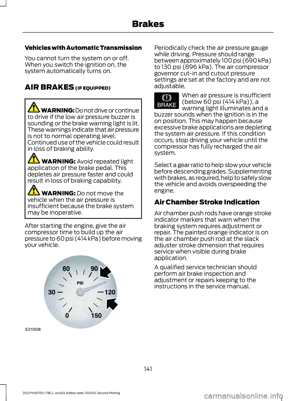
your vehicle. Periodically check the air pressure gauge
while driving. Pressure should range
between approximately 100 psi (690 kPa)
to
130 psi (896 kPa). The air compressor
governor cut-in and cutout pressure
settings are set at the factory and are not
adjustable. When air pressure is insufficient
(below
60 psi (414 kPa)), a
warning light illuminates and a
buzzer sounds when the ignition is in the
on position. This may happen because
excessive brake applications are depleting
the system air pressure. If this condition
occurs, stop driving your vehicle until the
compressor has fully recharged the air
system.
Select a gear ratio to help slow your vehicle
before descending grades. Supplementing
with brakes, as required, help to safely slow
the vehicle and avoids overspeeding the
engine.
Air Chamber Stroke Indication
Air chamber push rods have orange stroke
indicator markers that warn when the
braking system requires adjustment or
repair. The painted orange indicator is on
the air chamber push rod at the slack
adjuster stroke dimension that requires
service when visible during brake
application.
A qualified service technician should
perform air brake inspection and
adjustment or repairs keeping to the
instructions in the service manual.
141
2022 F650750 (TBC) , enUSA, Edition date: 202010, Second-Printing BrakesE210336 E206772
Page 145 of 379
Cam Brakes - Automatic Slack
Adjusters
WARNING: Do not manually adjust
the automatic slack adjusters to correct
excessive push rod stroke as it may result
in reduced brake effectiveness and a
vehicle crash. Excessive push rod stroke
indicates that a problem exists with the
automatic adjuster, with the installation
of the adjuster, or with foundation brake
components that manual adjustment
does not remedy. Seek service from a
qualified facility for excessive push rod
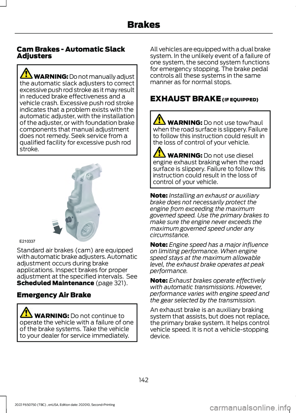
stroke. Standard air brakes (cam) are equipped
with automatic brake adjusters. Automatic
adjustment occurs during brake
applications. Inspect brakes for proper
adjustment at the specified intervals. See
Scheduled Maintenance (page 321).
Emergency Air Brake WARNING:
Do not continue to
operate the vehicle with a failure of one
of the brake systems. Take the vehicle
to your dealer for service immediately. All vehicles are equipped with a dual brake
system. In the unlikely event of a failure of
one system, the second system functions
for emergency stopping. The brake pedal
controls all these systems in the same
manner as for normal stops.
EXHAUST BRAKE
(IF EQUIPPED)
WARNING:
Do not use tow/haul
when the road surface is slippery. Failure
to follow this instruction could result in
the loss of control of your vehicle. WARNING:
Do not use diesel
engine exhaust braking when the road
surface is slippery. Failure to follow this
instruction could result in the loss of
control of your vehicle.
Note: Installing an exhaust or auxiliary
brake does not necessarily protect the
engine from exceeding the maximum
governed speed. Use the primary brakes to
make sure the engine never exceeds the
maximum governed speed under any
circumstance.
Note: Engine speed has a major influence
on limiting performance. When engine
speed stays at the maximum allowable
level, the exhaust brake operates at peak
performance.
Note: Exhaust brakes operate effectively
with automatic transmissions. However,
performance varies with engine speed and
the gear selected by the transmission.
An exhaust brake is an auxiliary braking
system that assists, but does not replace,
the primary brake system. It helps control
vehicle speed. It is not a vehicle-stopping
device.
142
2022 F650750 (TBC) , enUSA, Edition date: 202010, Second-Printing BrakesE210337
Page 182 of 379
ESSENTIAL TOWING CHECKS
See Load limits in the Load Carrying
chapter for load specification terms found
on the tire label and Safety Compliance
label and instructions on calculating your
vehicle's load.
Remember to account for the trailer
tongue weight as part of your vehicle load
when calculating the total vehicle weight.
Hitches
Do not use a hitch that either clamps onto
the bumper or attaches to the axle. You
must distribute the load in your trailer so
that 10-15% of the total weight of the
trailer is on the tongue.
Safety Chains
Note: Do not attach safety chains to the
bumper.
Always connect the safety chains to the
frame or hook retainers of your vehicle
hitch.
To connect the safety chains, cross the
chains under the trailer tongue and allow
enough slack for turning tight corners. Do
not allow the chains to drag on the ground.
Trailer Brakes WARNING:
Do not connect a
trailer's hydraulic brake system directly
to your vehicle's brake system. Your
vehicle may not have enough braking
power and your chances of having a
collision greatly increase.
Electric brakes and manual, automatic or
surge-type trailer brakes are safe if you
install them properly and adjust them to
the manufacturer's specifications. The
trailer brakes must meet local and federal
regulations. The rating for the tow vehicle's braking
system operation is at the gross vehicle
weight rating, not the gross combined
weight rating.
Trailer Lamps
WARNING:
Never connect any
trailer lamp wiring to the vehicle's tail
lamp wiring; this may damage the
electrical system resulting in fire. Contact
your authorized dealer as soon as
possible for assistance in proper trailer
tow wiring installation. Additional
electrical equipment may be required.
Trailer lamps are required on most towed
vehicles. Make sure all running lights, brake
lights, turn signals and hazard lights are
working.
Before Towing a Trailer
Practice turning, stopping and backing up
to get the feel of your vehicle-trailer
combination before starting on a trip.
When turning, make wider turns so the
trailer wheels clear curbs and other
obstacles.
When Towing a Trailer
• Check your hitch, electrical connections
and trailer wheel lug nuts thoroughly
after you have traveled
50 mph
(80 km/h).
• When stopped in congested or heavy
traffic during hot weather, place the
transmission in park (P) or neutral (N)
to aid engine and transmission cooling
and to help air conditioning
performance.
• Turn off the speed control with heavy
loads or in hilly terrain. The speed
control may turn off automatically
when you are towing on long, steep
grades.
179
2022 F650750 (TBC) , enUSA, Edition date: 202010, Second-Printing Towing
Page 192 of 379
JUMP STARTING THE VEHICLE
WARNING: Batteries normally
produce explosive gases which can
cause personal injury. Therefore, do not
allow flames, sparks or lighted
substances to come near the battery.
When working near the battery, always
shield your face and protect your eyes.
Always provide correct ventilation. WARNING:
Keep batteries out of
reach of children. Batteries contain
sulfuric acid. Avoid contact with skin,
eyes or clothing. Shield your eyes when
working near the battery to protect
against possible splashing of acid
solution. In case of acid contact with skin
or eyes, flush immediately with water for
a minimum of 15 minutes and get prompt
medical attention. If acid is swallowed,
call a physician immediately. WARNING:
Use only adequately
sized cables with insulated clamps.
Preparing Your Vehicle
Do not attempt to push-start your
automatic transmission vehicle.
Note: Attempting to push-start a vehicle
with an automatic transmission may cause
transmission damage.
Note: Use only a 12-volt supply to start your
vehicle.
Note: Do not disconnect the battery of the
disabled vehicle as this could damage the
vehicle electrical system.
Park the booster vehicle close to the hood
of the disabled vehicle, making sure the
two vehicles do not touch. Connecting the Jumper Cables WARNING:
Do not attach the
cables to fuel lines, engine rocker covers,
the intake manifold or electrical
components as grounding points. Stay
clear of moving parts. To avoid reverse
polarity connections, make sure that you
correctly identify the positive (+) and
negative (-) terminals on both the
disabled and booster vehicles before
connecting the cables. WARNING:
Do not attach the end
of the positive cable to the studs or
L-shaped eyelet located above the
positive (+) terminal of your vehicle ’s
battery. High current may flow through
and cause damage to the fuses. WARNING: Do not connect the end
of the second cable to the negative (-)
terminal of the battery to be jumped. A
spark may cause an explosion of the
gases that surround the battery.
Note: In the illustration, the bottom vehicle
represents the booster vehicle.
189
2022 F650750 (TBC) , enUSA, Edition date: 202010, Second-Printing Roadside Emergencies
Page 214 of 379
Engine starting (with parking brake applied)
Check the gauge (diesel engine) or indicator light (gasoline
engine) to verify the alternator is charging.
Voltmeter
Inspect for excessive free play in the steering linkages. The
steering wheel should have less than 2 in (5 cm) of free play
at its rim.
Steering linkage free play
Verify the parking brake holds the vehicle by gently trying to
pull forward with the parking brake applied.
Parking brake
Verify operation using the following procedure. Chock the
wheels, if necessary. Push in the parking brake and, on
tractors, push in the tractor parking brake knob:
Air brakes
1. Verify the air compressor or governor cutout pressure is
approximately 120 psi (827 kPa).
2. Turn off the engine, and then turn the key back to the on
position (without starting the engine).
3. Without the brake pedal applied, note the air pressure drop
for one minute. It should be less than 2 psi (14 kPa) for single
vehicles and
3 psi (21 kPa) for combination vehicles.
4. Press and hold the brake pedal with
90 psi (621 kPa) or
more. Make sure there is no more than a 3 psi (21 kPa) per
minute leak for single vehicles and a 4 psi (28 kPa) minute
leak for combination vehicles.
5. Pump the brake pedal to deplete the system of air pressure.
The warning light and tone should turn on at 57 psi (393 kPa).
6. Pump the brake pedal and make sure the parking brake
and trailer parking brake knobs pop out at
20 psi (138 kPa)
or higher.
Verify that the fluid level is in the proper operating range. See
Automatic Transmission Fluid Check
(page 241).
Automatic transmission
fluid Front of vehicle
Verify all exterior lights illuminate and are clean.
Lights
Check headlights function on high and low beam.
Verify reflectors are clean, unbroken and of proper color (red
on rear, amber elsewhere).
211
2022 F650750 (TBC) , enUSA, Edition date: 202010, Second-Printing Vehicle Inspection Guide
Page 224 of 379
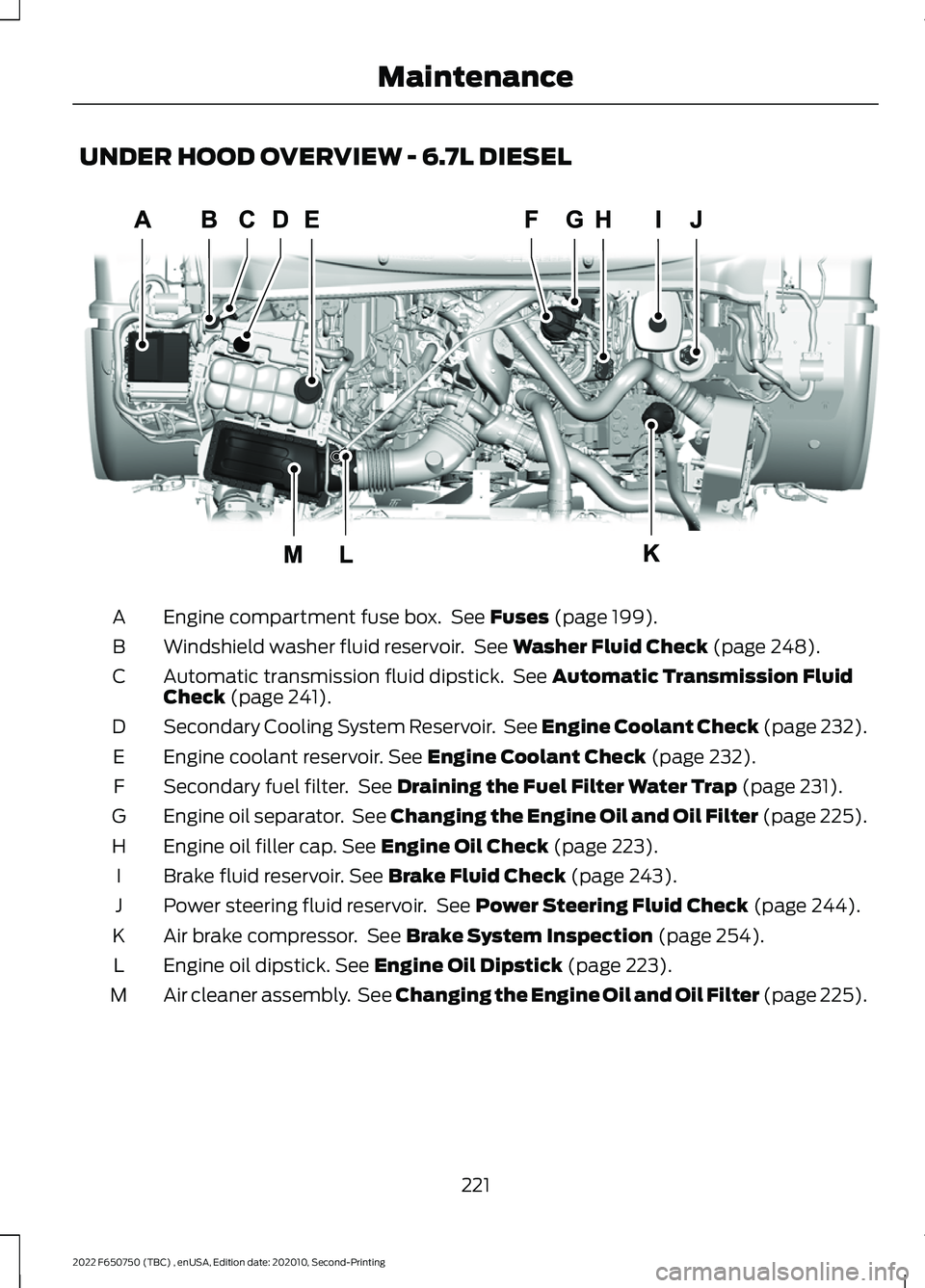
UNDER HOOD OVERVIEW - 6.7L DIESEL
Engine compartment fuse box. See Fuses (page 199).
A
Windshield washer fluid reservoir. See
Washer Fluid Check (page 248).
B
Automatic transmission fluid dipstick. See
Automatic Transmission Fluid
Check (page 241).
C
Secondary Cooling System Reservoir. See Engine Coolant Check (page 232).
D
Engine coolant reservoir.
See Engine Coolant Check (page 232).
E
Secondary fuel filter. See
Draining the Fuel Filter Water Trap (page 231).
F
Engine oil separator. See Changing the Engine Oil and Oil Filter (page 225).
G
Engine oil filler cap.
See Engine Oil Check (page 223).
H
Brake fluid reservoir.
See Brake Fluid Check (page 243).
I
Power steering fluid reservoir. See
Power Steering Fluid Check (page 244).
J
Air brake compressor. See
Brake System Inspection (page 254).
K
Engine oil dipstick.
See Engine Oil Dipstick (page 223).
L
Air cleaner assembly. See Changing the Engine Oil and Oil Filter (page 225).
M
221
2022 F650750 (TBC) , enUSA, Edition date: 202010, Second-Printing MaintenanceE313700
Page 225 of 379
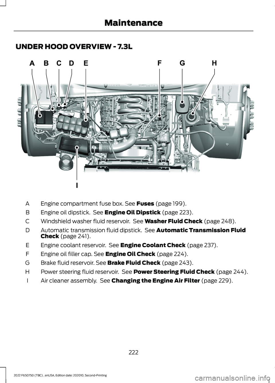
UNDER HOOD OVERVIEW - 7.3L
Engine compartment fuse box. See Fuses (page 199).
A
Engine oil dipstick. See
Engine Oil Dipstick (page 223).
B
Windshield washer fluid reservoir. See
Washer Fluid Check (page 248).
C
Automatic transmission fluid dipstick. See
Automatic Transmission Fluid
Check (page 241).
D
Engine coolant reservoir. See
Engine Coolant Check (page 237).
E
Engine oil filler cap.
See Engine Oil Check (page 224).
F
Brake fluid reservoir.
See Brake Fluid Check (page 243).
G
Power steering fluid reservoir. See
Power Steering Fluid Check (page 244).
H
Air cleaner assembly. See
Changing the Engine Air Filter (page 229).
I
222
2022 F650750 (TBC) , enUSA, Edition date: 202010, Second-Printing MaintenanceE330964
Page 244 of 379
4. Check the coolant level. If the coolant
level is at or below the minimum mark,
add prediluted coolant immediately.
5. When the engine temperature cools, you can re-start the engine. Have your
vehicle checked as soon as possible to
minimize engine damage.
Note: Driving your vehicle without repair
increases the chance of engine damage.
Engine Coolant Temperature
Management (If Equipped) WARNING:
To reduce the risk of
crash and injury, be prepared that the
vehicle speed may reduce and the
vehicle may not be able to accelerate
with full power until the coolant
temperature reduces.
If you tow a trailer with your vehicle, the
engine may temporarily reach a higher
temperature during severe operating
conditions, for example ascending a long
or steep grade in high ambient
temperatures.
At this time, you may notice the coolant
temperature gauge moves toward the red
zone and a message may appear in the
information display.
You may notice a reduction in vehicle
speed caused by reduced engine power in
order to manage the engine coolant
temperature. Your vehicle may enter this
mode if certain high-temperature and
high-load conditions take place. The
amount of speed reduction depends on
vehicle loading, grade and ambient
temperature. If this occurs, there is no
need to pull off the road. You can continue
to drive your vehicle. The air conditioning may turn on and off
during severe operating conditions to
protect the engine from overheating. When
the coolant temperature decreases to the
normal operating temperature, the air
conditioning turns on.
If the coolant temperature gauge moves
fully into the red zone, or if the coolant
temperature warning or service engine
soon messages appear in your information
display, do the following:
1. Pull off the road as soon as safely
possible and shift the transmission into
park (P).
2. Leave the engine running until the coolant temperature gauge needle
returns to the normal position. After
several minutes, if the temperature
does not drop, follow the remaining
steps.
3. Switch the engine off and wait for it to
cool. Check the coolant level.
4. If the coolant level is at or below the minimum mark, add prediluted coolant
immediately.
5. If the coolant level is normal, restart the engine and continue.
AUTOMATIC TRANSMISSION
FLUID CHECK
The transmission does not consume fluid.
However, check the fluid level if the
transmission is not working properly, for
example if the transmission slips, shifts
slowly or if there are signs of fluid loss.
Replace the transmission fluid and filter
on your vehicle at the specified service
interval. See
Scheduled Maintenance
(page 321).
Automatic transmission fluid expands
when warmed. To check the fluid level
consistently and accurately, do the
following:
241
2022 F650750 (TBC) , enUSA, Edition date: 202010, Second-Printing Maintenance