lock FORD F SERIES MOTORHOME AND COMMERCIAL CHASSIS 1999 10.G Owners Manual
[x] Cancel search | Manufacturer: FORD, Model Year: 1999, Model line: F SERIES MOTORHOME AND COMMERCIAL CHASSIS, Model: FORD F SERIES MOTORHOME AND COMMERCIAL CHASSIS 1999 10.GPages: 96, PDF Size: 0.57 MB
Page 8 of 96
3. The fuel cap may not have been properly installed and securely
tightened.
These temporary malfunctions can be corrected by filling the fuel tank
with good quality fuel and/or properly installing and securely tightening
the gas cap. After three driving cycles without these or any other
temporary malfunctions present, theService Engine Soonlight should
turn off. (A driving cycle consists of a cold engine startup followed by
mixed city/highway driving.) No additional vehicle service is required.
If theService Engine Soonlight remains on, have your vehicle serviced
at the first available opportunity.
Light is blinking:
Engine misfire is occurring which could damage your catalytic converter.
You should drive in a moderate fashion (avoid heavy acceleration and
deceleration) and have your vehicle serviced at the first available
opportunity.
Under engine misfire conditions, excessive exhaust temperatures
could damage the catalytic converter, the fuel system, interior
floor coverings or other vehicle components, possibly causing a fire.
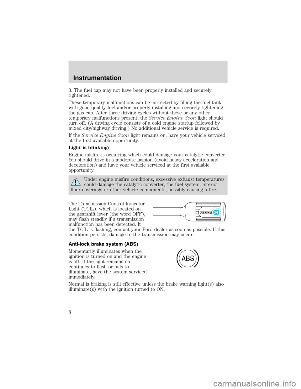
The Transmission Control Indicator
Light (TCIL), which is located on
the gearshift lever (the word OFF),
may flash steadily if a transmission
malfunction has been detected. It
the TCIL is flashing, contact your Ford dealer as soon as possible. If this
condition persists, damage to the transmission may occur.
Anti-lock brake system (ABS)
Momentarily illuminates when the
ignition is turned on and the engine
is off. If the light remains on,
continues to flash or fails to
illuminate, have the system serviced
immediately.
Normal is braking is still effective unless the brake warning light(s) also
illuminate(s) with the ignition turned to ON.
OVERDRIVE
ABS
Instrumentation
8
Page 9 of 96

Door ajar
Illuminates when the ignition is in
the ON or START position and any
door is open.
Fuel reset
Illuminates when the ignition is
turned to the ON position and the
fuel pump shut-off switch has been
triggered. For more information,
refer toFuel pump shut-off switch
in theRoadside emergencieschapter.
High beams
Illuminates when the high beam
headlamps are turned on.
Turn signal
Illuminates when the left or right
turn signal or the hazard lights are
turned on. Refer toExterior bulbs
in theMaintenance and care
chapter.
Safety belt warning chime
Chimes to remind you to fasten your safety belts.
Key-in-ignition warning chime
Sounds when the key is left in the ignition in the OFF/LOCK or ACC
position and the driver’s door is opened.
Headlamps on warning chime
Sounds when the headlamps or parking lamps are on, the ignition is off
(and the key is not in the ignition) and the driver’s door is opened.
DOOR
AJAR
FUEL
RESET
Instrumentation
9
Page 15 of 96
Flash to pass
Pull toward you to activate and
release to deactivate.
PANEL DIMMER CONTROL
Use to adjust the brightness of the
instrument panel during headlamp
and parklamp operation.
•Rotate up to brighten.
•Rotate down to dim.
•Rotate to full up position (past
detent) to turn on interior lamps.
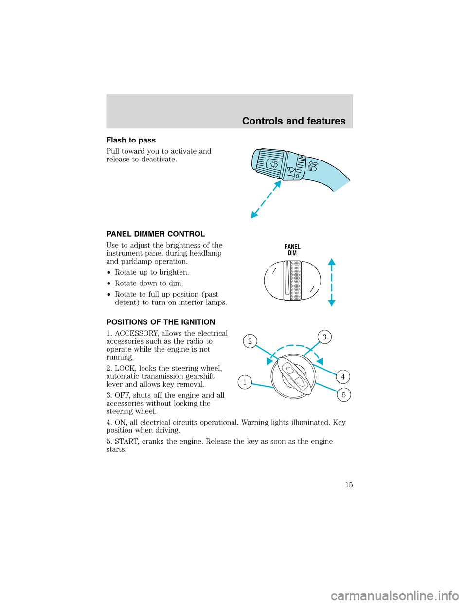
POSITIONS OF THE IGNITION
1. ACCESSORY, allows the electrical
accessories such as the radio to
operate while the engine is not
running.
2. LOCK, locks the steering wheel,
automatic transmission gearshift
lever and allows key removal.
3. OFF, shuts off the engine and all
accessories without locking the
steering wheel.
4. ON, all electrical circuits operational. Warning lights illuminated. Key
position when driving.
5. START, cranks the engine. Release the key as soon as the engine
starts.
PANEL
DIM
1
23
4
5
Controls and features
15
Page 23 of 96
Make sure the corresponding lights illuminate briefly. If a light fails to
illuminate, have the vehicle serviced.
•If the driver’s safety belt is fastened, the
light may not illuminate.
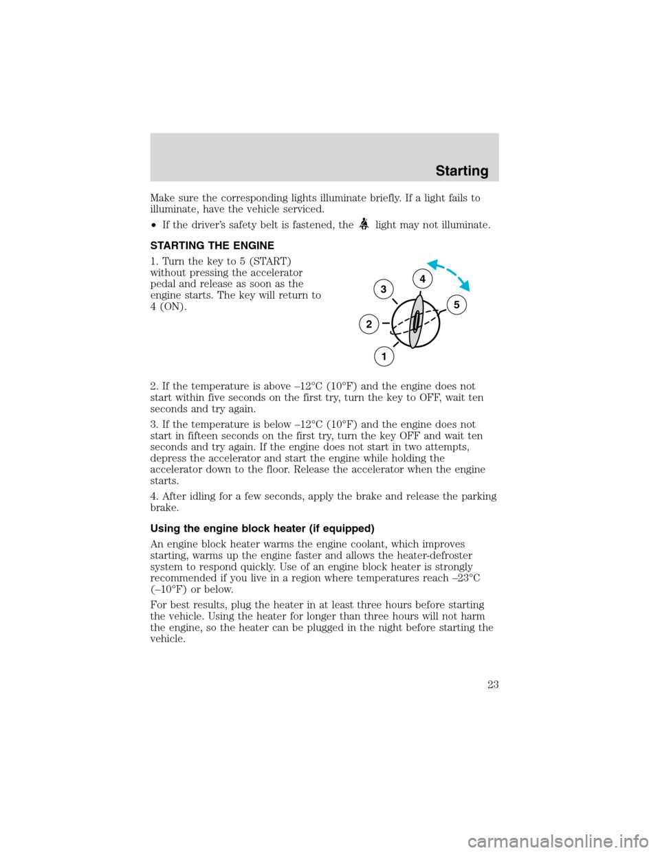
STARTING THE ENGINE
1. Turn the key to 5 (START)
without pressing the accelerator
pedal and release as soon as the
engine starts. The key will return to
4 (ON).
2. If the temperature is above –12°C (10°F) and the engine does not
start within five seconds on the first try, turn the key to OFF, wait ten
seconds and try again.
3. If the temperature is below –12°C (10°F) and the engine does not
start in fifteen seconds on the first try, turn the key OFF and wait ten
seconds and try again. If the engine does not start in two attempts,
depress the accelerator and start the engine while holding the
accelerator down to the floor. Release the accelerator when the engine
starts.
4. After idling for a few seconds, apply the brake and release the parking
brake.
Using the engine block heater (if equipped)
An engine block heater warms the engine coolant, which improves
starting, warms up the engine faster and allows the heater-defroster
system to respond quickly. Use of an engine block heater is strongly
recommended if you live in a region where temperatures reach –23°C
(–10°F) or below.
For best results, plug the heater in at least three hours before starting
the vehicle. Using the heater for longer than three hours will not harm
the engine, so the heater can be plugged in the night before starting the
vehicle.
3
2
1
5
4
Starting
23
Page 25 of 96
BRAKES
Your service brakes are self-adjusting. Refer to the Scheduled
maintenance guide for scheduled maintenance.
Occasional brake noise is normal and often does not indicate a
performance concern with the vehicle’s brake system. In normal
operation, automotive brake systems may emit occasional or intermittent
squeal or groan noises when the brakes are applied. Such noises are
usually heard during the first few brake applications in the morning;
however, they may be heard at any time while braking and can be
aggravated by environmental conditions such as cold, heat, moisture,
road dust, salt or mud. If a “metal-to-metal,” “continuous grinding” or
“continuous squeal” sound is present while braking, the brake linings
may be worn-out and should be inspected by a qualified service
technician.
If you are driving down a long or steep hill, shift to a lower gear.
Do not apply your brakes continuously, as they may overheat
and become less effective.
Anti-lock brake system (ABS) (if equipped)
On vehicles equipped with an anti-lock braking system (ABS), a noise
from the hydraulic pump motor and pulsation in the pedal may be
observed during ABS braking events. Pedal pulsation coupled with noise
while braking under panic conditions or on loose gravel, bumps, wet or
snowy roads is normal and indicates proper functioning of the vehicle’s
anti-lock brake system. The ABS performs a self-check at 17 km/h
(10 mph) after you start the engine and begin to drive away. A brief
mechanical noise may be heard during this test. This is normal. If a
malfunction is found, the ABS warning light will come on. If the vehicle
has continuous vibration or shudder in the steering wheel while braking,
the vehicle should be inspected by a qualified service technician.
Driving
25
Page 26 of 96
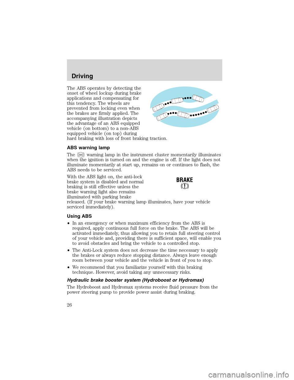
The ABS operates by detecting the
onset of wheel lockup during brake
applications and compensating for
this tendency. The wheels are
prevented from locking even when
the brakes are firmly applied. The
accompanying illustration depicts
the advantage of an ABS equipped
vehicle (on bottom) to a non-ABS
equipped vehicle (on top) during
hard braking with loss of front braking traction.
ABS warning lamp
The
ABSwarning lamp in the instrument cluster momentarily illuminates
when the ignition is turned on and the engine is off. If the light does not
illuminate momentarily at start up, remains on or continues to flash, the
ABS needs to be serviced.
With the ABS light on, the anti-lock
brake system is disabled and normal
braking is still effective unless the
brake warning light also remains
illuminated with parking brake
released. (If your brake warning lamp illuminates, have your vehicle
serviced immediately).
Using ABS
•In an emergency or when maximum efficiency from the ABS is
required, apply continuous full force on the brake. The ABS will be
activated immediately, thus allowing you to retain full steering control
of your vehicle and, providing there is sufficient space, will enable you
to avoid obstacles and bring the vehicle to a controlled stop.
•The Anti-Lock system does not decrease the time necessary to apply
the brakes or always reduce stopping distance. Always leave enough
room between your vehicle and the vehicle in front of you to stop.
•We recommend that you familiarize yourself with this braking
technique. However, avoid taking any unnecessary risks.
Hydraulic brake booster system (Hydroboost or Hydromax)
The Hydroboost and Hydromax systems receive fluid pressure from the
power steering pump to provide power assist during braking.
Driving
26
Page 28 of 96

Always set the parking brake fully and make sure the gearshift is
latched in P (Park). Turn off the ignition whenever you leave
your vehicle.
The parking brake is not recommended to stop a moving vehicle.
However, if the normal brakes fail, the parking brake can be used to stop
your vehicle in an emergency. Since the parking brake applies only the
transmission mounted parking brake assembly, the vehicle’s stopping
distance will increase greatly and the handling of your vehicle will be
adversely affected.
Push the service brake pedal with
your foot and pull the parking brake
release handle to release the
parking brake.
TRANSMISSION OPERATION
Brake-shift interlock
This vehicle is equipped with a brake-shift interlock feature that prevents
the gearshift from being moved from P (Park) unless the brake pedal is
depressed.
If you cannot move the gearshift out of P (Park) with the brake pedal
depressed:
1. Apply the parking brake, turn ignition key to LOCK, then remove the
key.
2. Insert the key and turn it to OFF. Apply the brake pedal and shift to N
(Neutral).
Driving
28
Page 30 of 96
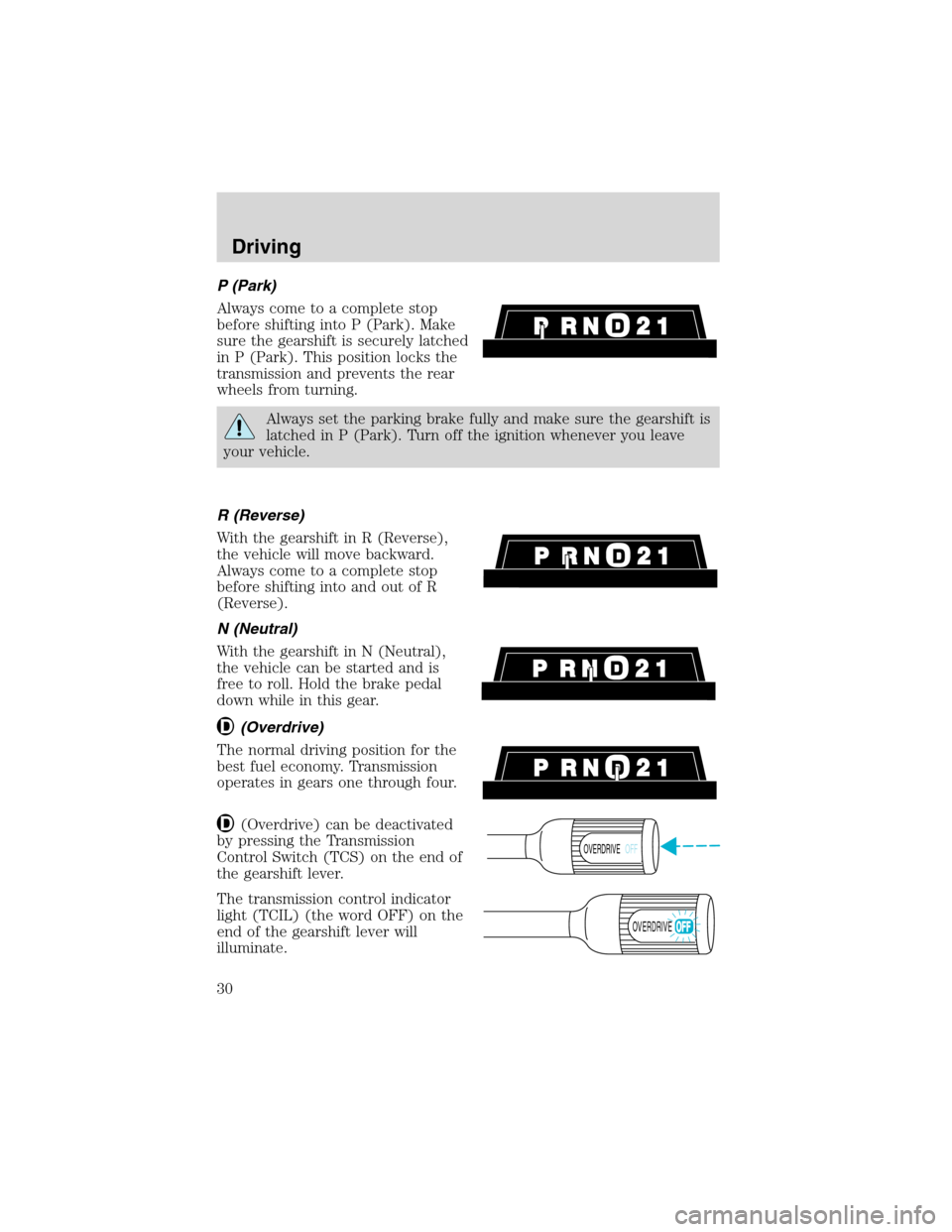
P (Park)
Always come to a complete stop
before shifting into P (Park). Make
sure the gearshift is securely latched
in P (Park). This position locks the
transmission and prevents the rear
wheels from turning.
Always set the parking brake fully and make sure the gearshift is
latched in P (Park). Turn off the ignition whenever you leave
your vehicle.
R (Reverse)
With the gearshift in R (Reverse),
the vehicle will move backward.
Always come to a complete stop
before shifting into and out of R
(Reverse).
N (Neutral)
With the gearshift in N (Neutral),
the vehicle can be started and is
free to roll. Hold the brake pedal
down while in this gear.
(Overdrive)
The normal driving position for the
best fuel economy. Transmission
operates in gears one through four.
(Overdrive) can be deactivated
by pressing the Transmission
Control Switch (TCS) on the end of
the gearshift lever.
The transmission control indicator
light (TCIL) (the word OFF) on the
end of the gearshift lever will
illuminate.
OVERDRIVEOFF
OVERDRIVE
Driving
30
Page 41 of 96

Fuse/Relay
LocationFuse Amp
RatingDescription
9 20A Trailer tow Electric Brake controller feed,
Body builder right rear turn/stop feed, Body
builder left rear turn/stop feed, Body builder
stop lamp feed, Trailer left turn/stop fuse
feed, Trailer right turn/stop fuse feed
10 5A Instrument cluster memory
11 30A Wiper motor/module power feed
12 10A Trailer tow right turn feed
13 10A ABS Module
14 10A Warning chime module, Power brake assist
module*, Instrument cluster power,
Instrument cluster warning lamps,
Transmission control switch
15 15A Left turn signal relay contacts
16 20A Body builder battery (+12V) feed
17 5A Body builder radio feed
18 — Not Used
19 5A Headlamp relay
20 — Not Used
21 15A Right turn signal relay contacts
22 — Not Used
23 — Not Used
24 — Not Used
25 10A Right headlamp
26 10A Speed control module, Brake shift interlock
actuator
27 — Not used
28 — Not used
29 — Not used
30 — Not used
31 10A Left headlamp
32 10A Backup lamp feed
Roadside emergencies
41
Page 44 of 96
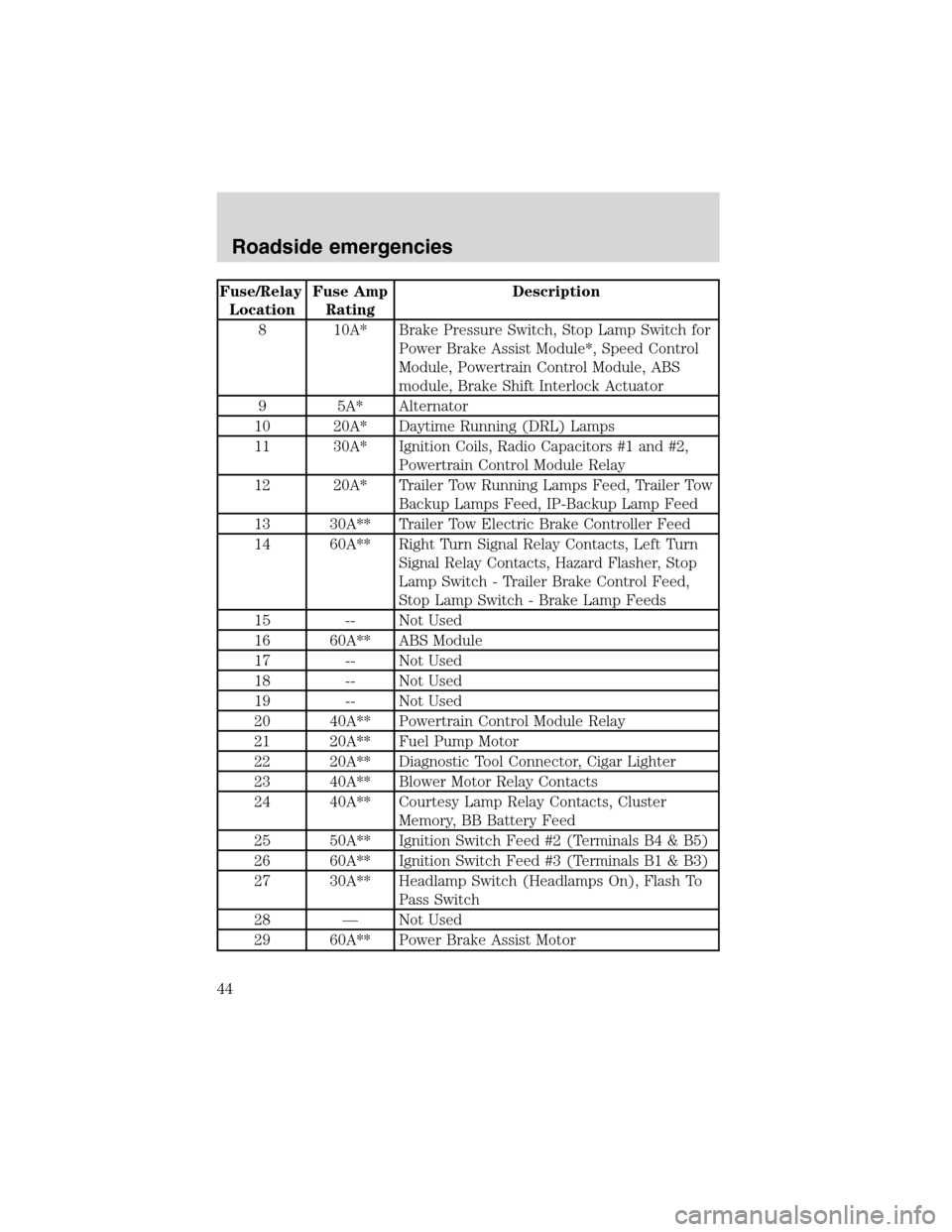
Fuse/Relay
LocationFuse Amp
RatingDescription
8 10A* Brake Pressure Switch, Stop Lamp Switch for
Power Brake Assist Module*, Speed Control
Module, Powertrain Control Module, ABS
module, Brake Shift Interlock Actuator
9 5A* Alternator
10 20A* Daytime Running (DRL) Lamps
11 30A* Ignition Coils, Radio Capacitors #1 and #2,
Powertrain Control Module Relay
12 20A* Trailer Tow Running Lamps Feed, Trailer Tow
Backup Lamps Feed, IP-Backup Lamp Feed
13 30A** Trailer Tow Electric Brake Controller Feed
14 60A** Right Turn Signal Relay Contacts, Left Turn
Signal Relay Contacts, Hazard Flasher, Stop
Lamp Switch - Trailer Brake Control Feed,
Stop Lamp Switch - Brake Lamp Feeds
15 -- Not Used
16 60A** ABS Module
17 -- Not Used
18 -- Not Used
19 -- Not Used
20 40A** Powertrain Control Module Relay
21 20A** Fuel Pump Motor
22 20A** Diagnostic Tool Connector, Cigar Lighter
23 40A** Blower Motor Relay Contacts
24 40A** Courtesy Lamp Relay Contacts, Cluster
Memory, BB Battery Feed
25 50A** Ignition Switch Feed #2 (Terminals B4 & B5)
26 60A** Ignition Switch Feed #3 (Terminals B1 & B3)
27 30A** Headlamp Switch (Headlamps On), Flash To
Pass Switch
28 — Not Used
29 60A** Power Brake Assist Motor
Roadside emergencies
44