oil FORD F SERIES MOTORHOME AND COMMERCIAL CHASSIS 1999 10.G Owners Manual
[x] Cancel search | Manufacturer: FORD, Model Year: 1999, Model line: F SERIES MOTORHOME AND COMMERCIAL CHASSIS, Model: FORD F SERIES MOTORHOME AND COMMERCIAL CHASSIS 1999 10.GPages: 96, PDF Size: 0.57 MB
Page 4 of 96
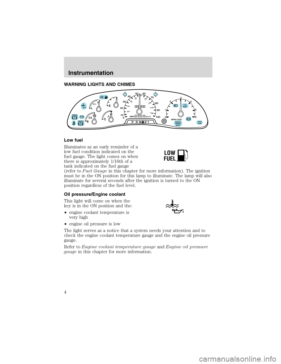
WARNING LIGHTS AND CHIMES
Low fuel
Illuminates as an early reminder of a
low fuel condition indicated on the
fuel gauge. The light comes on when
there is approximately 1/16th of a
tank indicated on the fuel gauge
(refer toFuel Gaugein this chapter for more information). The ignition
must be in the ON position for this lamp to illuminate. The lamp will also
illuminate for several seconds after the ignition is turned to the ON
position regardless of the fuel level.
Oil pressure/Engine coolant
This light will come on when the
key is in the ON position and the:
•engine coolant temperature is
very high
•engine oil pressure is low
The light serves as a notice that a system needs your attention and to
check the engine coolant temperature gauge and the engine oil pressure
gauge.
Refer toEngine coolant temperature gaugeandEngine oil pressure
gaugein this chapter for more information.
F
E
CH H
L
18
8
PRN 21LOW
FUEL
BRAKE!+ -+ -000000000
0
50
60
70
20
10
0 3040
80
90
100
20406080
100
120
140
180
MPH km/h
1
02
RPMx1000
3
4
5
6
SERVICE
ENGINE
SOONABS
FUEL
RESET
DOOR
AJARBRAKE
LOW
FUEL
Instrumentation
4
Page 10 of 96

GAUGES
Fuel gauge
Displays approximately how much
fuel is in the fuel tank (when the
key is in the ON position). The
ignition should be in the OFF
position while the vehicle is being
refueled. When the gauge first
indicates empty, there is a small
amount of reserve fuel in the tank.
When refueling the vehicle from
empty indication, the amount of fuel
that can be added will be less than the advertised capacity due to the
reserve fuel.
Engine oil pressure gauge
This shows the engine oil pressure
in the system. Sufficient pressure
exists as long as the needle remains
in the normal range (the area
between the “L” and “H”).
If the gauge indicates low pressure,
stop the vehicle as soon as safely
possible and switch off the engine
immediately. Check the oil level.
Add oil if needed (refer toEngine
oilin theMaintenance and care
chapter). If the oil level is correct, have your vehicle checked at your
dealership or by a qualified technician.
F
E
CH H
L
18
8
PRN 21LOW
FUEL
+ -+ -000000000
0
50
60
70
20
10
0 3040
80
90
100
20406080
100
120
140
180
MPH km/hBRAKE!
1
02
RPMx1000
3
4
5
6
SERVICE
ENGINE
SOONABSFUEL
RESETDOOR
AJARBRAKE
L
H
Instrumentation
10
Page 40 of 96

The fuses are coded as follows.
Fuse/Relay
LocationFuse Amp
RatingDescription
1 20A Right turn signal relay coil, Left turn signal
relay coil, Right turn indicator, Left turn
indicator, Body builder right rear turn/stop
feed, Body builder left rear turn/stop feed
2 — Not used
3 — Not used
4 15A Courtesy lamp relay, Interior lamp feed
5 10A Body builder accessory feed (accessory and
run)
6 10A Trailer tow left turn feed
7 15A Blower motor relay coil
8 — Not used
1234
5
7
689101142
43
44 13 12 14
15 16 17
19 18
2021 22 23
25 24
26 27 28 29
31 30 32 33 3435
37
3638 3940
41
RELAY 1RELAY 2 RELAY 3
Roadside emergencies
40
Page 43 of 96
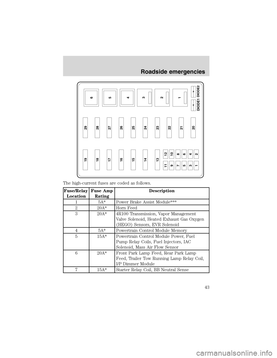
The high-current fuses are coded as follows.
Fuse/Relay
LocationFuse Amp
RatingDescription
1 5A* Power Brake Assist Module***
2 20A* Horn Feed
3 20A* 4R100 Transmission, Vapor Management
Valve Solenoid, Heated Exhaust Gas Oxygen
(HEGO) Sensors, EVR Solenoid
4 5A* Powertrain Control Module Memory
5 15A* Powertrain Control Module Power, Fuel
Pump Relay Coils, Fuel Injectors, IAC
Solenoid, Mass Air Flow Sensor
6 20A* Front Park Lamp Feed, Rear Park Lamp
Feed, Trailer Tow Running Lamp Relay Coil,
I/P Dimmer Module
7 15A* Starter Relay Coil, BB Neutral Sense
19 29
18 28
17 27
16 26
15 25
14 24
13
11 12
910
78
56
34
1223
22
21
20
6
5
4
3
2
1DIODE2
DIODE1
Roadside emergencies
43
Page 44 of 96
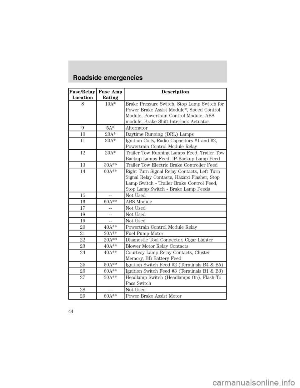
Fuse/Relay
LocationFuse Amp
RatingDescription
8 10A* Brake Pressure Switch, Stop Lamp Switch for
Power Brake Assist Module*, Speed Control
Module, Powertrain Control Module, ABS
module, Brake Shift Interlock Actuator
9 5A* Alternator
10 20A* Daytime Running (DRL) Lamps
11 30A* Ignition Coils, Radio Capacitors #1 and #2,
Powertrain Control Module Relay
12 20A* Trailer Tow Running Lamps Feed, Trailer Tow
Backup Lamps Feed, IP-Backup Lamp Feed
13 30A** Trailer Tow Electric Brake Controller Feed
14 60A** Right Turn Signal Relay Contacts, Left Turn
Signal Relay Contacts, Hazard Flasher, Stop
Lamp Switch - Trailer Brake Control Feed,
Stop Lamp Switch - Brake Lamp Feeds
15 -- Not Used
16 60A** ABS Module
17 -- Not Used
18 -- Not Used
19 -- Not Used
20 40A** Powertrain Control Module Relay
21 20A** Fuel Pump Motor
22 20A** Diagnostic Tool Connector, Cigar Lighter
23 40A** Blower Motor Relay Contacts
24 40A** Courtesy Lamp Relay Contacts, Cluster
Memory, BB Battery Feed
25 50A** Ignition Switch Feed #2 (Terminals B4 & B5)
26 60A** Ignition Switch Feed #3 (Terminals B1 & B3)
27 30A** Headlamp Switch (Headlamps On), Flash To
Pass Switch
28 — Not Used
29 60A** Power Brake Assist Motor
Roadside emergencies
44
Page 48 of 96
Never use wheels or lug
nuts different than the
original equipment as this could
damage the wheel or mounting
system. This damage could allow
the wheels to come off while the
vehicle is being driven.
15. Replace any wheel trim.
16. Stow the jack, handle and lug wrench.
17. Unblock the wheels.
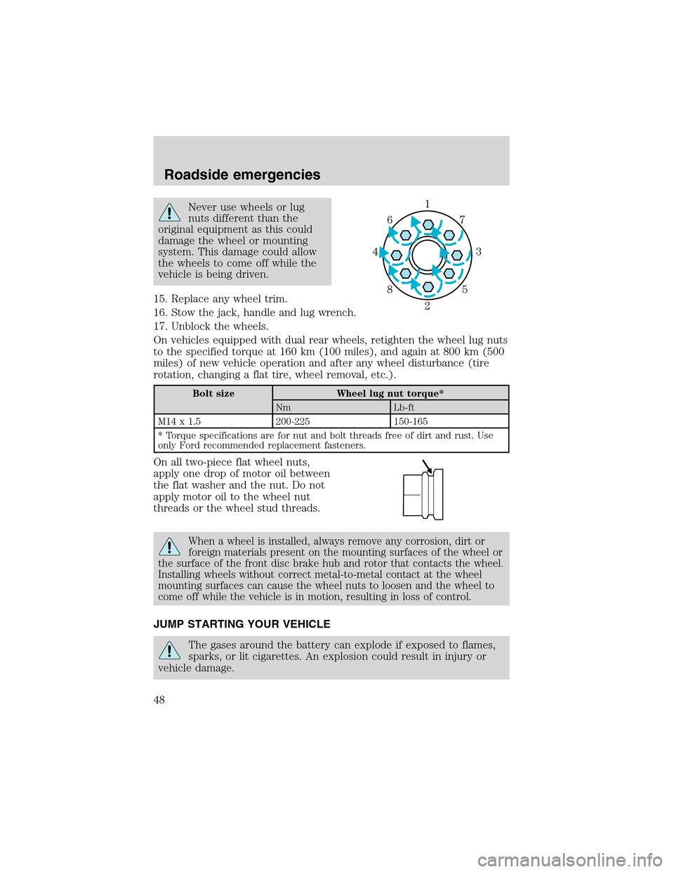
On vehicles equipped with dual rear wheels, retighten the wheel lug nuts
to the specified torque at 160 km (100 miles), and again at 800 km (500
miles) of new vehicle operation and after any wheel disturbance (tire
rotation, changing a flat tire, wheel removal, etc.).
Bolt size Wheel lug nut torque*
Nm Lb-ft
M14 x 1.5 200-225 150-165
* Torque specifications are for nut and bolt threads free of dirt and rust. Use
only Ford recommended replacement fasteners.
On all two-piece flat wheel nuts,
apply one drop of motor oil between
the flat washer and the nut. Do not
apply motor oil to the wheel nut
threads or the wheel stud threads.
When a wheel is installed, always remove any corrosion, dirt or
foreign materials present on the mounting surfaces of the wheel or
the surface of the front disc brake hub and rotor that contacts the wheel.
Installing wheels without correct metal-to-metal contact at the wheel
mounting surfaces can cause the wheel nuts to loosen and the wheel to
come off while the vehicle is in motion, resulting in loss of control.
JUMP STARTING YOUR VEHICLE
The gases around the battery can explode if exposed to flames,
sparks, or lit cigarettes. An explosion could result in injury or
vehicle damage.
1
3 4
27 6
5 8
Roadside emergencies
48
Page 55 of 96
Do not start your engine with the air cleaner removed and do
not remove it while the engine is running.
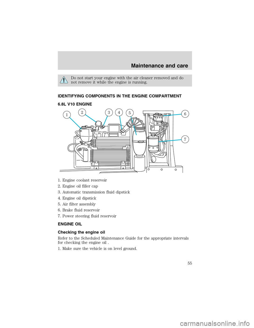
IDENTIFYING COMPONENTS IN THE ENGINE COMPARTMENT
6.8L V10 ENGINE
1. Engine coolant reservoir
2. Engine oil filler cap
3. Automatic transmission fluid dipstick
4. Engine oil dipstick
5. Air filter assembly
6. Brake fluid reservoir
7. Power steering fluid reservoir
ENGINE OIL
Checking the engine oil
Refer to the Scheduled Maintenance Guide for the appropriate intervals
for checking the engine oil .
1. Make sure the vehicle is on level ground.
124356
7
Maintenance and care
55
Page 56 of 96

2. Turn the engine off and wait a few minutes for the oil to drain into the
oil pan.
3. Set the parking brake and ensure the gearshift is securely latched in P
(Park).
4. Open the hood. Protect yourself from engine heat.
5. Locate and carefully remove the
engine oil level indicator (dipstick).
6. Wipe the indicator clean. Insert the indicator fully, then remove it
again.
•If the oil level isbetween the MIN and MAX marks,the oil level is
acceptable.DO NOT ADD OIL.
•If the oil level is below the MIN mark, add enough oil to raise the level
within the MIN-MAX range.
•Oil levels above the MAX mark may cause engine damage. Some oil
must be removed from the engine by a service technician.
7. Put the indicator back in and ensure it is fully seated.
Adding engine oil
1. Check the engine oil. For instructions, refer toChecking the engine
oilin this chapter.
2. If the engine oil level is not within the MIN and MAX ranges, add only
certified engine oil of the recommended viscosity. Remove the engine oil
filler cap and use a funnel to pour the engine oil into the opening.
3. Recheck the engine oil level. Make sure the oil level is not above the
MAX mark on the engine oil level indicator (dipstick).
MAX MIN
Maintenance and care
56
Page 57 of 96

4. Install the indicator and ensure it is fully seated.
5. Fully install the engine oil filler cap by turning the filler cap clockwise
until three clicks can be heard.
To avoid possible oil loss, DO NOT operate the vehicle with the
engine oil level indicator and/or the engine oil filler cap removed.
Engine oil and filter recommendations
Look for this Certification
Trademark.
Use SAE 5W-30 motor oil certified for gasoline engines by the American
Petroleum Institute (API).
Motor oil displaying the API Certification Trademark will meet all
requirements for your vehicle’s engine.
Ford oil specification is WSS-M2C153-G.
Do not use supplemental engine oil additives, oil treatments or engine
treatments. They are unnecessary and could, under certain conditions,
lead to engine damage which is not covered by your warranty.
Change your engine oil and filter according to the appropriate schedule
listed in the Scheduled Maintenance Guide.
Ford production and aftermarket (Motorcraft) oil filters are designed for
added engine protection and long life. If a replacement oil filter is used
that does not meet Ford material and design specifications, startup
engine noises or knock may be experienced.
It is recommended you use the appropriate Motorcraft oil filter (or
another brand meeting Ford specifications) for your engine application.
Maintenance and care
57
Page 75 of 96

The scheduled maintenance items listed in the Scheduled Maintenance
Guide are essential to the life and performance of your vehicle and to its
emissions system.
If other than Ford, Motorcraft or Ford-authorized parts are used for
maintenance replacements or for service of components affecting
emission control, such non-Ford parts should be equivalent to genuine
Ford Motor Company parts in performance and durability.
Do not park, idle, or drive your vehicle in dry grass or other dry
ground cover. The emission system heats up the engine
compartment and exhaust system, which can start a fire.
Illumination of the charging system warning light, “Service Engine Soon”
light or the temperature warning light, fluid leaks, strange odors, smoke
or loss of oil pressure, could indicate that the emission control system is
not working properly.
Exhaust leaks may result in entry of harmful and potentially
lethal fumes into the passenger compartment.
Do not make any unauthorized changes to your vehicle or engine. By
law, vehicle owners and anyone who manufactures, repairs, services,
sells, leases, trades vehicles, or supervises a fleet of vehicles are not
permitted to intentionally remove an emission control device or prevent
it from working. Information about your vehicle’s emission system is on
the Vehicle Emission Control Information Decal located on or near the
engine. This decal identifies engine displacement and gives some tune up
specifications.
Please consult your “Warranty Guide” for complete emission warranty
information.
Readiness for Inspection/Maintenance (I/M) testing
In some localities, it may be a legal requirement to pass an I/M test of
the on-board diagnostics system. If your “Check Engine/Service Engine
Soon” light is on, refer to the description in theWarning Lights and
Chimessection of theInstrumentationchapter. Your vehicle may not
pass the I/M test with the “Check Engine/Service Engine Soon” light on.
If the vehicle’s powertrain system or its battery has just been serviced,
the on-board diagnostics system is reset to a “not ready for I/M test”
Maintenance and care
75