battery FORD F150 2010 12.G Owner's Manual
[x] Cancel search | Manufacturer: FORD, Model Year: 2010, Model line: F150, Model: FORD F150 2010 12.GPages: 419, PDF Size: 3.17 MB
Page 325 of 419
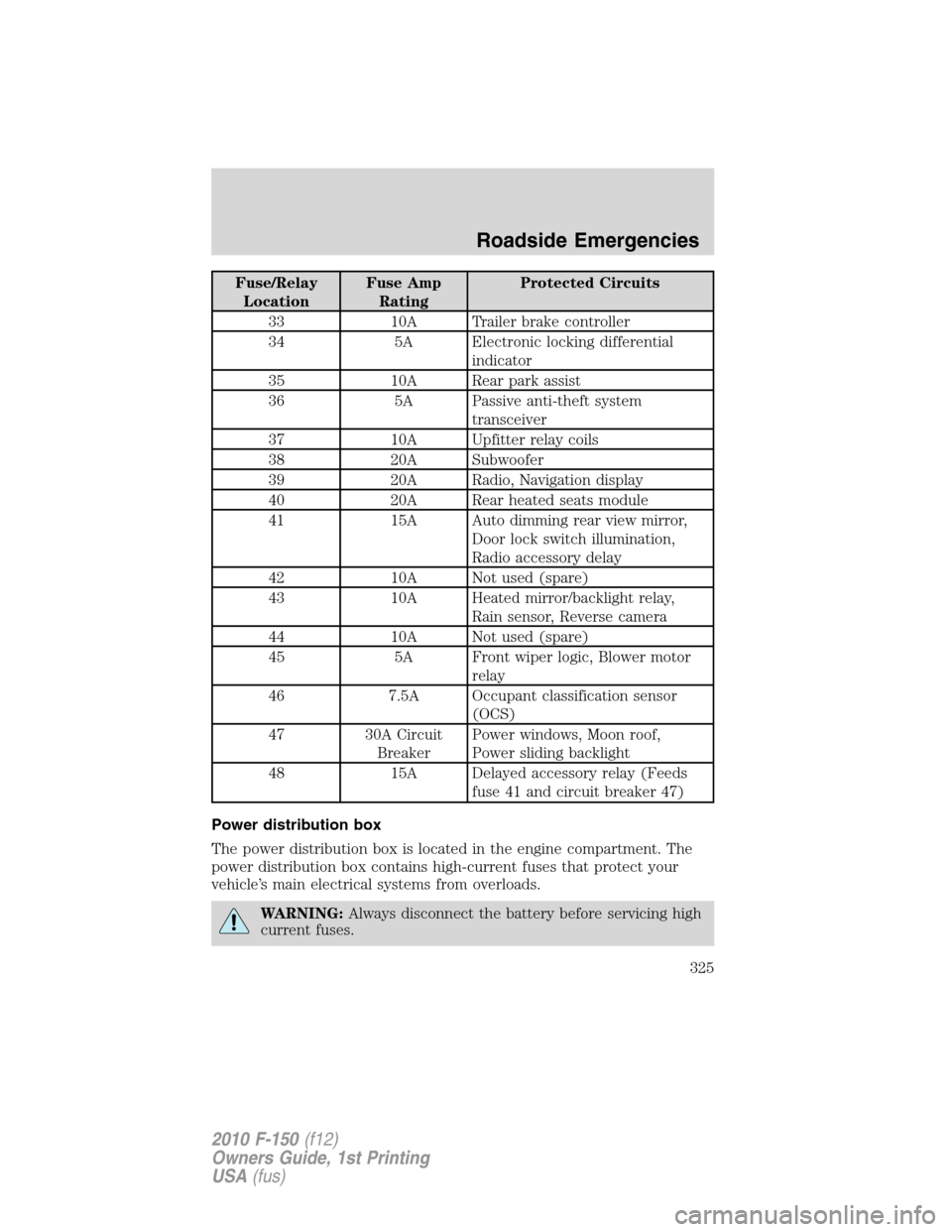
Fuse/Relay
LocationFuse Amp
RatingProtected Circuits
33 10A Trailer brake controller
34 5A Electronic locking differential
indicator
35 10A Rear park assist
36 5A Passive anti-theft system
transceiver
37 10A Upfitter relay coils
38 20A Subwoofer
39 20A Radio, Navigation display
40 20A Rear heated seats module
41 15A Auto dimming rear view mirror,
Door lock switch illumination,
Radio accessory delay
42 10A Not used (spare)
43 10A Heated mirror/backlight relay,
Rain sensor, Reverse camera
44 10A Not used (spare)
45 5A Front wiper logic, Blower motor
relay
46 7.5A Occupant classification sensor
(OCS)
47 30A Circuit
BreakerPower windows, Moon roof,
Power sliding backlight
48 15A Delayed accessory relay (Feeds
fuse 41 and circuit breaker 47)
Power distribution box
The power distribution box is located in the engine compartment. The
power distribution box contains high-current fuses that protect your
vehicle’s main electrical systems from overloads.
WARNING:Always disconnect the battery before servicing high
current fuses.
Roadside Emergencies
325
2010 F-150(f12)
Owners Guide, 1st Printing
USA(fus)
Page 326 of 419
WARNING:To reduce risk of electrical shock, always replace
the cover to the Power Distribution Box before reconnecting the
battery or refilling fluid reservoirs.
If the battery has been disconnected and reconnected, refer to the
Batterysection of theMaintenance and Specificationschapter.
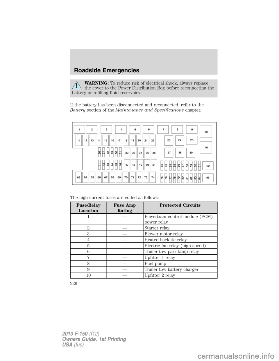
The high-current fuses are coded as follows:
Fuse/Relay
LocationFuse Amp
RatingProtected Circuits
1 — Powertrain control module (PCM)
power relay
2 — Starter relay
3 — Blower motor relay
4 — Heated backlite relay
5 — Electric fan relay (high speed)
6 — Trailer tow park lamp relay
7 — Upfitter 1 relay
8 — Fuel pump
9 — Trailer tow battery charger
10 — Upfitter 2 relay
Roadside Emergencies
326
2010 F-150(f12)
Owners Guide, 1st Printing
USA(fus)
Page 327 of 419
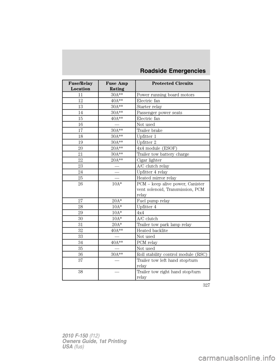
Fuse/Relay
LocationFuse Amp
RatingProtected Circuits
11 30A** Power running board motors
12 40A** Electric fan
13 30A** Starter relay
14 30A** Passenger power seats
15 40A** Electric fan
16 — Not used
17 30A** Trailer brake
18 30A** Upfitter 1
19 30A** Upfitter 2
20 20A** 4x4 module (ESOF)
21 30A** Trailer tow battery charge
22 20A** Cigar lighter
23 — A/C clutch relay
24 — Upfitter 4 relay
25 — Heated mirror relay
26 10A* PCM – keep alive power, Canister
vent solenoid, Transmission, PCM
relay
27 20A* Fuel pump relay
28 10A* Upfitter 4
29 10A* 4x4
30 10A* A/C clutch
31 20A* Trailer tow park lamp relay
32 40A** Heated backlite
33 — Not used
34 40A** PCM relay
35 — Not used
36 30A** Roll stability control module (RSC)
37 — Trailer tow left hand stop/turn
relay
38 — Trailer tow right hand stop/turn
relay
Roadside Emergencies
327
2010 F-150(f12)
Owners Guide, 1st Printing
USA(fus)
Page 328 of 419
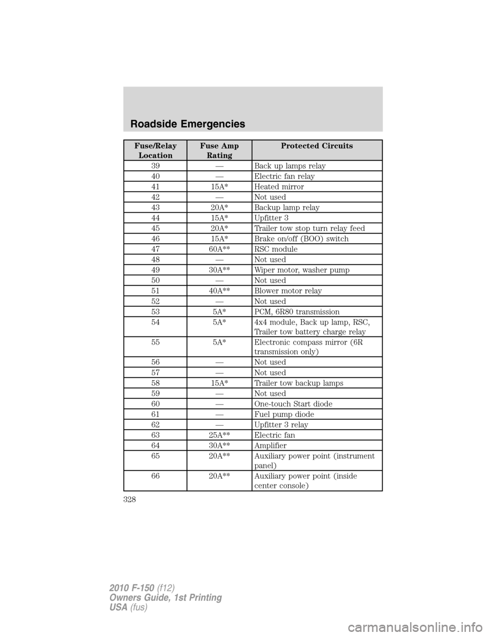
Fuse/Relay
LocationFuse Amp
RatingProtected Circuits
39 — Back up lamps relay
40 — Electric fan relay
41 15A* Heated mirror
42 — Not used
43 20A* Backup lamp relay
44 15A* Upfitter 3
45 20A* Trailer tow stop turn relay feed
46 15A* Brake on/off (BOO) switch
47 60A** RSC module
48 — Not used
49 30A** Wiper motor, washer pump
50 — Not used
51 40A** Blower motor relay
52 — Not used
53 5A* PCM, 6R80 transmission
54 5A* 4x4 module, Back up lamp, RSC,
Trailer tow battery charge relay
55 5A* Electronic compass mirror (6R
transmission only)
56 — Not used
57 — Not used
58 15A* Trailer tow backup lamps
59 — Not used
60 — One-touch Start diode
61 — Fuel pump diode
62 — Upfitter 3 relay
63 25A** Electric fan
64 30A** Amplifier
65 20A** Auxiliary power point (instrument
panel)
66 20A** Auxiliary power point (inside
center console)
Roadside Emergencies
328
2010 F-150(f12)
Owners Guide, 1st Printing
USA(fus)
Page 329 of 419
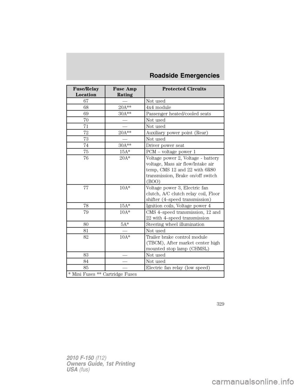
Fuse/Relay
LocationFuse Amp
RatingProtected Circuits
67 — Not used
68 20A** 4x4 module
69 30A** Passenger heated/cooled seats
70 — Not used
71 — Not used
72 20A** Auxiliary power point (Rear)
73 — Not used
74 30A** Driver power seat
75 15A* PCM – voltage power 1
76 20A* Voltage power 2, Voltage - battery
voltage, Mass air flow/Intake air
temp, CMS 12 and 22 with 6R80
transmission, Brake on/off switch
(BOO)
77 10A* Voltage power 3, Electric fan
clutch, A/C clutch relay coil, Floor
shifter (4–speed transmission)
78 15A* Ignition coils, Voltage power 4
79 10A* CMS 4–speed transmission, 12 and
22 with 4–speed transmission
80 5A* Steering wheel illumination
81 — Not used
82 10A* Trailer brake control module
(TBCM), After market center high
mounted stop lamp (CHMSL)
83 — Not used
84 — Not used
85 — Electric fan relay (low speed)
* Mini Fuses ** Cartridge Fuses
Roadside Emergencies
329
2010 F-150(f12)
Owners Guide, 1st Printing
USA(fus)
Page 338 of 419
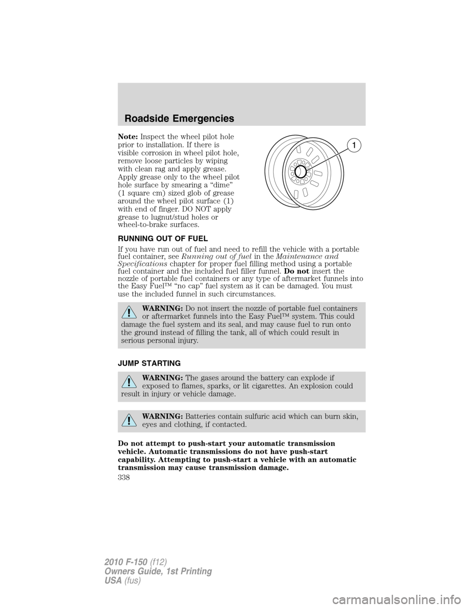
Note:Inspect the wheel pilot hole
prior to installation. If there is
visible corrosion in wheel pilot hole,
remove loose particles by wiping
with clean rag and apply grease.
Apply grease only to the wheel pilot
hole surface by smearing a “dime”
(1 square cm) sized glob of grease
around the wheel pilot surface (1)
with end of finger. DO NOT apply
grease to lugnut/stud holes or
wheel-to-brake surfaces.
RUNNING OUT OF FUEL
If you have run out of fuel and need to refill the vehicle with a portable
fuel container, seeRunning out of fuelin theMaintenance and
Specificationschapter for proper fuel filling method using a portable
fuel container and the included fuel filler funnel.Do notinsert the
nozzle of portable fuel containers or any type of aftermarket funnels into
the Easy Fuel™ “no cap” fuel system as it can be damaged. You must
use the included funnel in such circumstances.
WARNING:Do not insert the nozzle of portable fuel containers
or aftermarket funnels into the Easy Fuel™ system. This could
damage the fuel system and its seal, and may cause fuel to run onto
the ground instead of filling the tank, all of which could result in
serious personal injury.
JUMP STARTING
WARNING:The gases around the battery can explode if
exposed to flames, sparks, or lit cigarettes. An explosion could
result in injury or vehicle damage.
WARNING:Batteries contain sulfuric acid which can burn skin,
eyes and clothing, if contacted.
Do not attempt to push-start your automatic transmission
vehicle. Automatic transmissions do not have push-start
capability. Attempting to push-start a vehicle with an automatic
transmission may cause transmission damage.
Roadside Emergencies
338
2010 F-150(f12)
Owners Guide, 1st Printing
USA(fus)
Page 339 of 419
Preparing your vehicle
When the battery is disconnected or a new battery is installed, the
automatic transmission must relearn its shift strategy. As a result, the
transmission may have firm and/or soft shifts. This operation is
considered normal and will not affect function or durability of the
transmission. Over time, the adaptive learning process will fully update
transmission operation.
1.Use only a 12–volt supply to start your vehicle.
2. Do not disconnect the battery of the disabled vehicle as this could
damage the vehicle’s electrical system.
3. Park the booster vehicle close to the hood of the disabled vehicle
making sure the two vehiclesdo nottouch. Set the parking brake on
both vehicles and stay clear of the engine cooling fan and other moving
parts.
4. Check all battery terminals and remove any excessive corrosion before
you attach the battery cables. Ensure that vent caps are tight and level.
5. Turn the heater fan on in both vehicles to protect from any electrical
surges. Turn all other accessories off.
Connecting the jumper cables
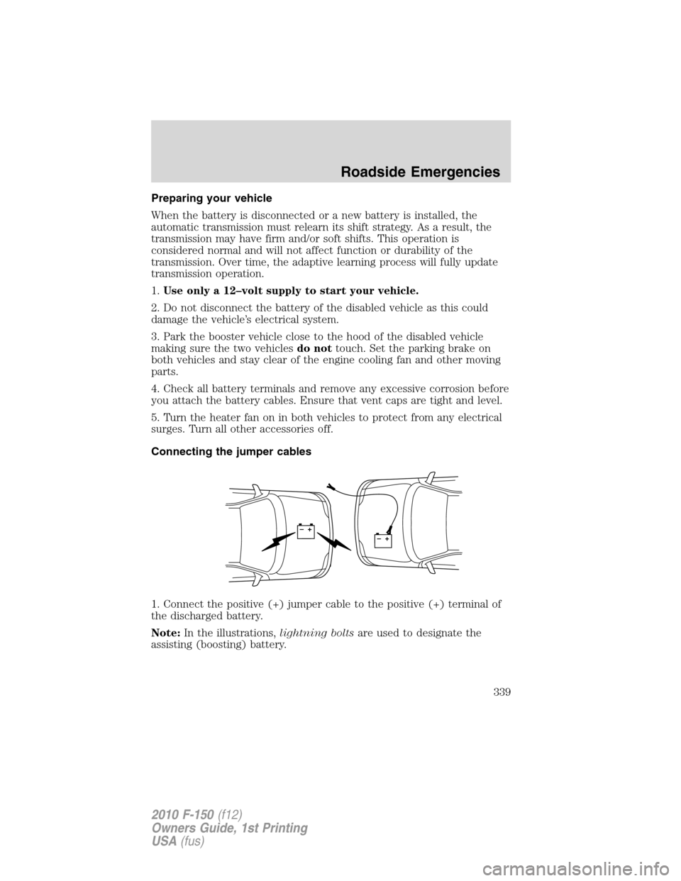
1. Connect the positive (+) jumper cable to the positive (+) terminal of
the discharged battery.
Note:In the illustrations,lightning boltsare used to designate the
assisting (boosting) battery.
+–+–
Roadside Emergencies
339
2010 F-150(f12)
Owners Guide, 1st Printing
USA(fus)
Page 340 of 419
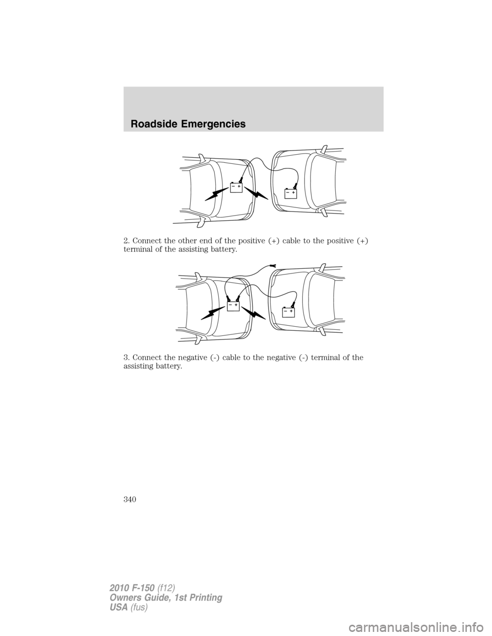
2. Connect the other end of the positive (+) cable to the positive (+)
terminal of the assisting battery.
3. Connect the negative (-) cable to the negative (-) terminal of the
assisting battery.
+–+–
+–+–
Roadside Emergencies
340
2010 F-150(f12)
Owners Guide, 1st Printing
USA(fus)
Page 341 of 419
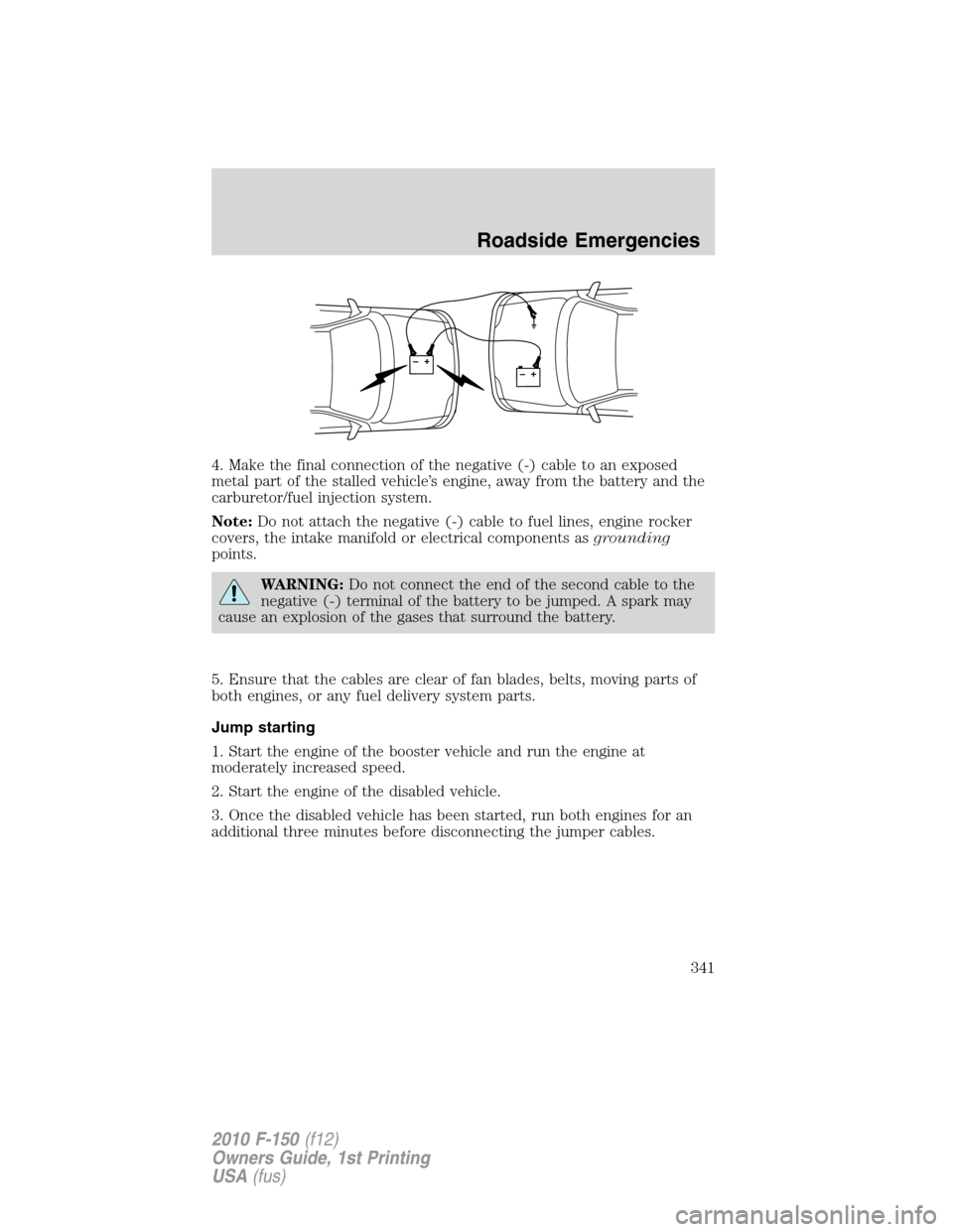
4. Make the final connection of the negative (-) cable to an exposed
metal part of the stalled vehicle’s engine, away from the battery and the
carburetor/fuel injection system.
Note:Do not attach the negative (-) cable to fuel lines, engine rocker
covers, the intake manifold or electrical components asgrounding
points.
WARNING:Do not connect the end of the second cable to the
negative (-) terminal of the battery to be jumped. A spark may
cause an explosion of the gases that surround the battery.
5. Ensure that the cables are clear of fan blades, belts, moving parts of
both engines, or any fuel delivery system parts.
Jump starting
1. Start the engine of the booster vehicle and run the engine at
moderately increased speed.
2. Start the engine of the disabled vehicle.
3. Once the disabled vehicle has been started, run both engines for an
additional three minutes before disconnecting the jumper cables.
+–+–
Roadside Emergencies
341
2010 F-150(f12)
Owners Guide, 1st Printing
USA(fus)
Page 342 of 419
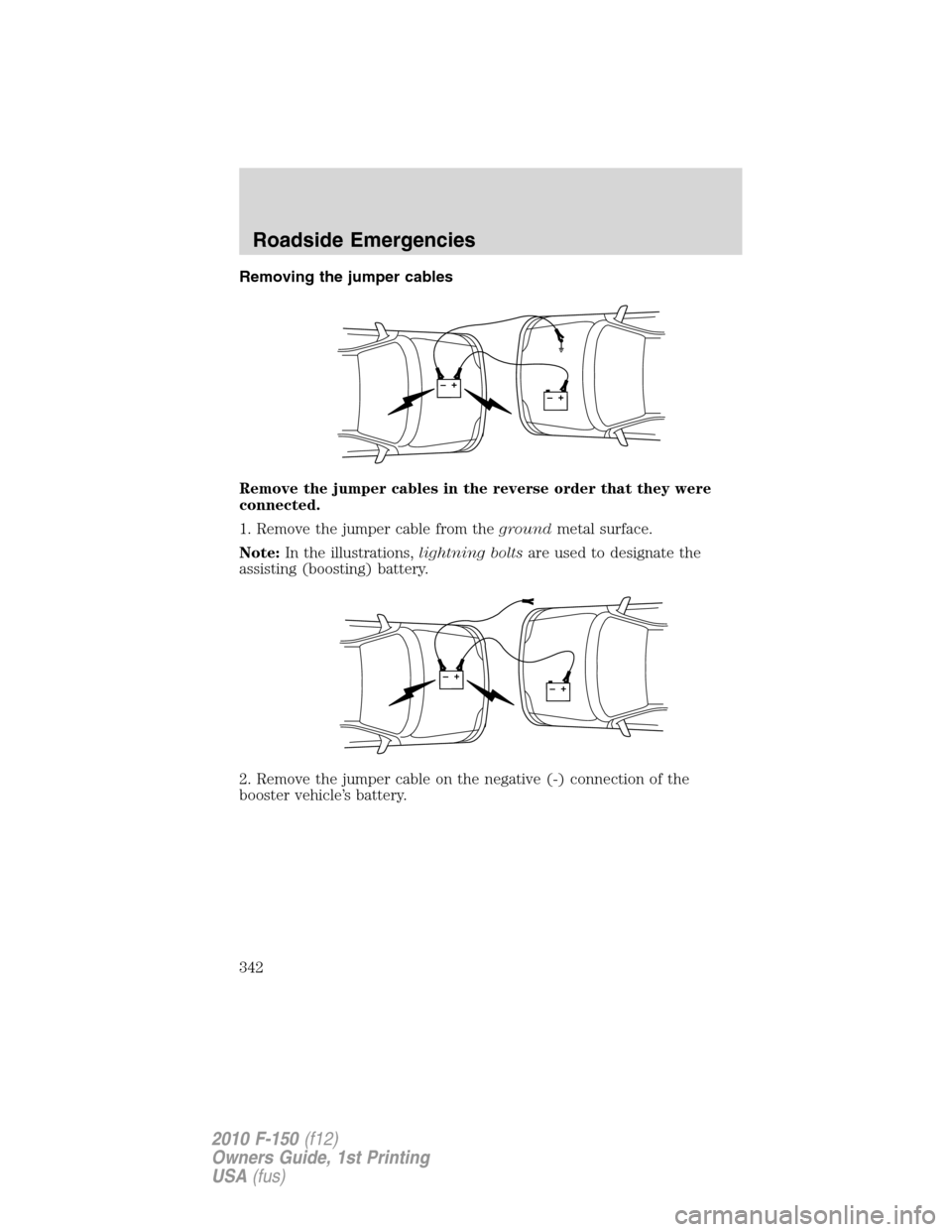
Removing the jumper cables
Remove the jumper cables in the reverse order that they were
connected.
1. Remove the jumper cable from thegroundmetal surface.
Note:In the illustrations,lightning boltsare used to designate the
assisting (boosting) battery.
2. Remove the jumper cable on the negative (-) connection of the
booster vehicle’s battery.
+–+–
+–+–
Roadside Emergencies
342
2010 F-150(f12)
Owners Guide, 1st Printing
USA(fus)