FORD F250 SUPER DUTY 2020 Owners Manual
Manufacturer: FORD, Model Year: 2020, Model line: F250 SUPER DUTY, Model: FORD F250 SUPER DUTY 2020Pages: 633, PDF Size: 9.18 MB
Page 351 of 633
3. Make sure that your vehicle is on level
ground.
4. Switch the engine off and wait 15 minutes for the oil to drain into the oil
pan. Checking the engine oil level too
soon after you switch the engine off
may result in an inaccurate reading.
5. Open the hood. See Opening and
Closing the Hood (page 342).
6. Remove the dipstick and wipe it with a clean, lint-free cloth. See
Under
Hood Overview (page 344).
7. Replace the dipstick and remove it again to check the oil level. See
Engine Oil Dipstick
(page 346).
8. Make sure that the oil level is between
the maximum and minimum marks. If
the oil level is at the minimum mark,
add oil immediately. See
Capacities
and Specifications (page 450).
9. If the oil level is correct, replace the dipstick and make sure it is fully seated.
Note: Do not remove the dipstick when the
engine is running.
Note: If the oil level is between the
maximum and minimum marks, the oil level
is acceptable. Do not add oil.
Note: The oil consumption of new engines
reaches its normal level after approximately
3,000 mi (5,000 km)
.
Adding Engine Oil WARNING: Do not remove the filler
cap when the engine is running.
Do not use supplemental engine oil
additives because they are unnecessary
and could lead to engine damage that may
not be covered by the vehicle Warranty.
To top up the engine oil level do the
following: 1. Clean the area surrounding the engine
oil filler cap before you remove it.
2. Remove the engine oil filler cap. See Under Hood Overview
(page 344).
Turn it counterclockwise and remove
it.
3. Add engine oil of the proper viscosity and grade that meets Ford
specifications. See
Capacities and
Specifications (page 450). You may
have to use a funnel to pour the engine
oil into the opening.
4. Recheck the oil level.
5. If the oil level is correct, replace the dipstick and make sure it is fully seated.
6. Replace the engine oil filler cap. Turn it clockwise until you feel a strong
resistance.
Note: Do not add oil further than the
maximum mark. Oil levels above the
maximum mark may cause engine damage.
Note: Make sure you install the oil filler cap
correctly.
Note: Soak up any spillage with an
absorbent cloth immediately.
Engine lubrication for severe
service operation
The following conditions define severe
operation for which engine operation with
SAE 5W-40 oil which meets Ford
specification, WSS-M2C171-F1, is
recommended. Oil and oil filter change
intervals will be determined by the
Intelligent Oil Life Monitor™ as noted
previously.
ENGINE OIL CHECK - 7.3L
To check the engine oil level consistently
and accurately, do the following:
348
Super Duty (TFE) Canada/United States of America, enUSA, Edition date: 201909, Second-Printing Maintenance
Page 352 of 633
1.
Make sure the parking brake is on. Make
sure the transmission is in park (P) or
neutral (N).
2. Run the engine until it reaches normal operating temperature.
3. Make sure that your vehicle is on level ground.
4. Switch the engine off and wait 15 minutes for the oil to drain into the oil
pan. Checking the engine oil level too
soon after you switch the engine off
may result in an inaccurate reading.
5. Open the hood. See Maintenance
(page 342).
6. Remove the dipstick and wipe it with a clean, lint-free cloth. See
Maintenance
(page 342).
7. Replace the dipstick and remove it again to check the oil level. See
Maintenance
(page 342).
8. Make sure that the oil level is between
the maximum and minimum marks. If
the oil level is at the minimum mark,
add oil immediately. See
Capacities
and Specifications (page 433).
9. If the oil level is correct, replace the dipstick and make sure it is fully seated.
Note: Do not remove the dipstick when the
engine is running.
Note: If the oil level is between the
maximum and minimum marks, the oil level
is acceptable. Do not add oil.
Note: The oil consumption of new engines
reaches its normal level after approximately
3,000 mi (5,000 km)
.
Adding Engine Oil WARNING: Do not remove the filler
cap when the engine is running. Do not use supplemental engine oil
additives because they are unnecessary
and could lead to engine damage that may
not be covered by the vehicle Warranty.
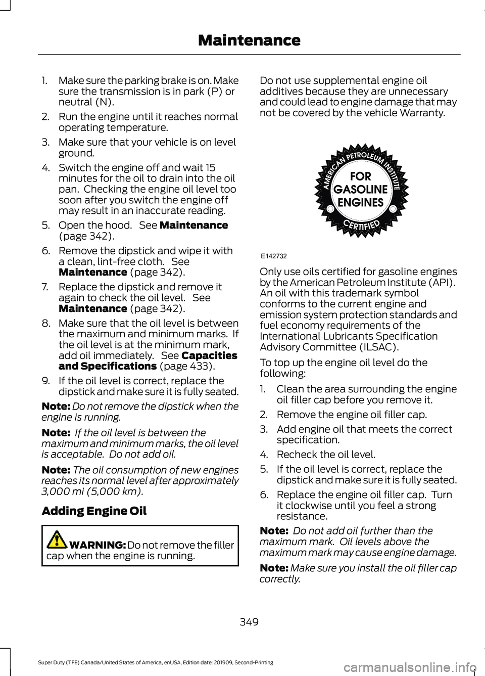
Only use oils certified for gasoline engines
by the American Petroleum Institute (API).
An oil with this trademark symbol
conforms to the current engine and
emission system protection standards and
fuel economy requirements of the
International Lubricants Specification
Advisory Committee (ILSAC).
To top up the engine oil level do the
following:
1. Clean the area surrounding the engine
oil filler cap before you remove it.
2. Remove the engine oil filler cap.
3. Add engine oil that meets the correct specification.
4. Recheck the oil level.
5. If the oil level is correct, replace the dipstick and make sure it is fully seated.
6. Replace the engine oil filler cap. Turn it clockwise until you feel a strong
resistance.
Note: Do not add oil further than the
maximum mark. Oil levels above the
maximum mark may cause engine damage.
Note: Make sure you install the oil filler cap
correctly.
349
Super Duty (TFE) Canada/United States of America, enUSA, Edition date: 201909, Second-Printing MaintenanceE142732
Page 353 of 633
Note:
Soak up any spillage with an
absorbent cloth immediately.
CHANGING THE ENGINE OIL
AND OIL FILTER WARNING: Do not handle a hot oil
filter with bare hands. WARNING: Continuous contact
with used motor oil has caused cancer
in laboratory mice. Protect your skin by
washing with soap and water.
If your vehicle is equipped with a diesel
engine, an Intelligent Oil Life Monitor™
calculates the proper oil change service
interval. When the information display
indicates: OIL CHANGE REQUIRED, change
the engine oil and oil filter. See
Information Displays
(page 112).
The engine oil filter protects your engine
by filtering harmful, abrasive or sludge
particles and particles significantly smaller
than most available will-fit filters. See
Motorcraft Parts
(page 435).
1. Unscrew the oil filter and oil pan drain plug and wait for the oil to drain.
2. Replace the filter.
3. Reinstall the oil pan drain plug.
4. Refill the engine with new oil. See Engine Specifications
(page 433).
5. For diesel engines, you need to reset the Intelligent Oil Life Monitor™. See
Information Displays
(page 112). Engine lubrication for severe
service operation
The following conditions define severe
operation for which engine operation with
SAE 5W-40 API CJ-4 is recommended. Oil
and oil filter change intervals will be
determined by the Intelligent Oil Life
Monitor™ as noted previously.
•
Frequent or extended idling (over 10
minutes per hour of normal driving).
• Low-speed operation/stationary use.
• If vehicle is operated in sustained
ambient temperatures below
-9°F
(-23°C) or above 100°F (38°C).
• Frequent low-speed operation,
consistent heavy traffic less than
25 mph (40 km/h)
.
• Operating in severe dust conditions.
• Operating the vehicle off road.
• Towing a trailer over
1,000 mi
(1,600 km).
• Sustained, high-speed driving at Gross
Vehicle Weight Rating (maximum
loaded weight for vehicle operation).
• Use of fuels with sulfur content other
than ultra-low sulfur diesel (ULSD).
• Use of high-sulfur diesel fuel.
OIL CHANGE INDICATOR
RESET
Use the information display controls on
the steering wheel to reset the oil change
indicator.
350
Super Duty (TFE) Canada/United States of America, enUSA, Edition date: 201909, Second-Printing Maintenance
Page 354 of 633
From the main menu scroll to:
Action and description
Message
Press the down arrow
button, then from this menu
scroll to the following
message.
Truck Info
Press the OK button.
Mainten-
ance
Monitor
Press the down arrow
button, then from this menu
scroll to the following
message.
Oil Life:
xxx%
Press the
OK button.
Oil Life
Press and hold the
OK
button until the instrument
cluster displays the
following message.
Oil Life
Hold OK to
Reset
Oil Life: 100%
When the oil change indic-
ator resets the instrument
cluster displays 100%.
Repeat the process if the oil
change indicator does not
reset.
CHANGING THE ENGINE AIR
FILTER - 6.2L WARNING:
To reduce the risk of
vehicle damage and personal burn
injuries, do not start your engine with the
air cleaner removed and do not remove
it while the engine is running.
Use the correct specification air filter
element. See
Motorcraft Parts (page
435). Note:
Failure to use the correct air filter
element may result in severe engine
damage. Resulting component damage
may not be covered by the vehicle Warranty.
Change the air filter element at the correct
service interval. See
Scheduled
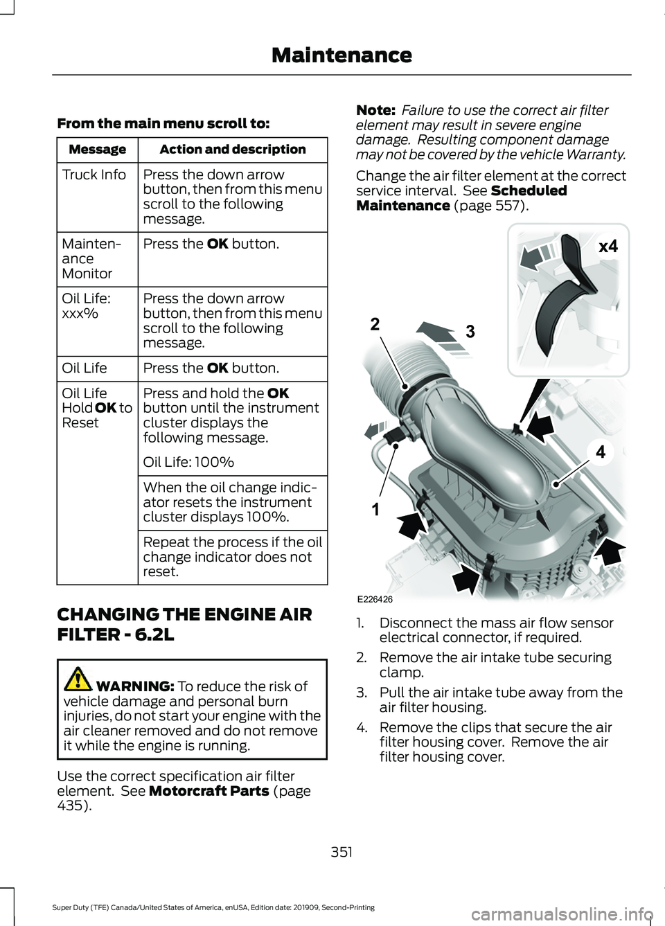
Maintenance (page 557). 1. Disconnect the mass air flow sensor
electrical connector, if required.
2. Remove the air intake tube securing clamp.
3. Pull the air intake tube away from the air filter housing.
4. Remove the clips that secure the air filter housing cover. Remove the air
filter housing cover.
351
Super Duty (TFE) Canada/United States of America, enUSA, Edition date: 201909, Second-Printing MaintenanceE226426
x4
1
2
4
3
Page 355 of 633
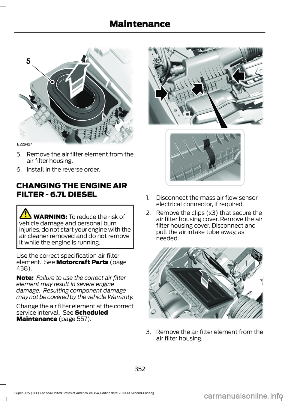
5.
Remove the air filter element from the
air filter housing.
6. Install in the reverse order.
CHANGING THE ENGINE AIR
FILTER - 6.7L DIESEL WARNING: To reduce the risk of
vehicle damage and personal burn
injuries, do not start your engine with the
air cleaner removed and do not remove
it while the engine is running.
Use the correct specification air filter
element. See
Motorcraft Parts (page
438).
Note: Failure to use the correct air filter
element may result in severe engine
damage. Resulting component damage
may not be covered by the vehicle Warranty.
Change the air filter element at the correct
service interval. See
Scheduled
Maintenance (page 557). 1. Disconnect the mass air flow sensor
electrical connector, if required.
2. Remove the clips (x3) that secure the air filter housing cover. Remove the air
filter housing cover. Disconnect and
pull the air intake tube away, as
needed. 3.
Remove the air filter element from the
air filter housing.
352
Super Duty (TFE) Canada/United States of America, enUSA, Edition date: 201909, Second-Printing MaintenanceE226427
5 E310318 E310319
Page 356 of 633
4. Remove the auxiliary foam filter from
the air filter housing.
5. To install, reverse the removal procedure. The housing cover can be
oscillated slightly left to right to assist
with installation as needed, until
positioned such that all three clips can
be re-engaged.
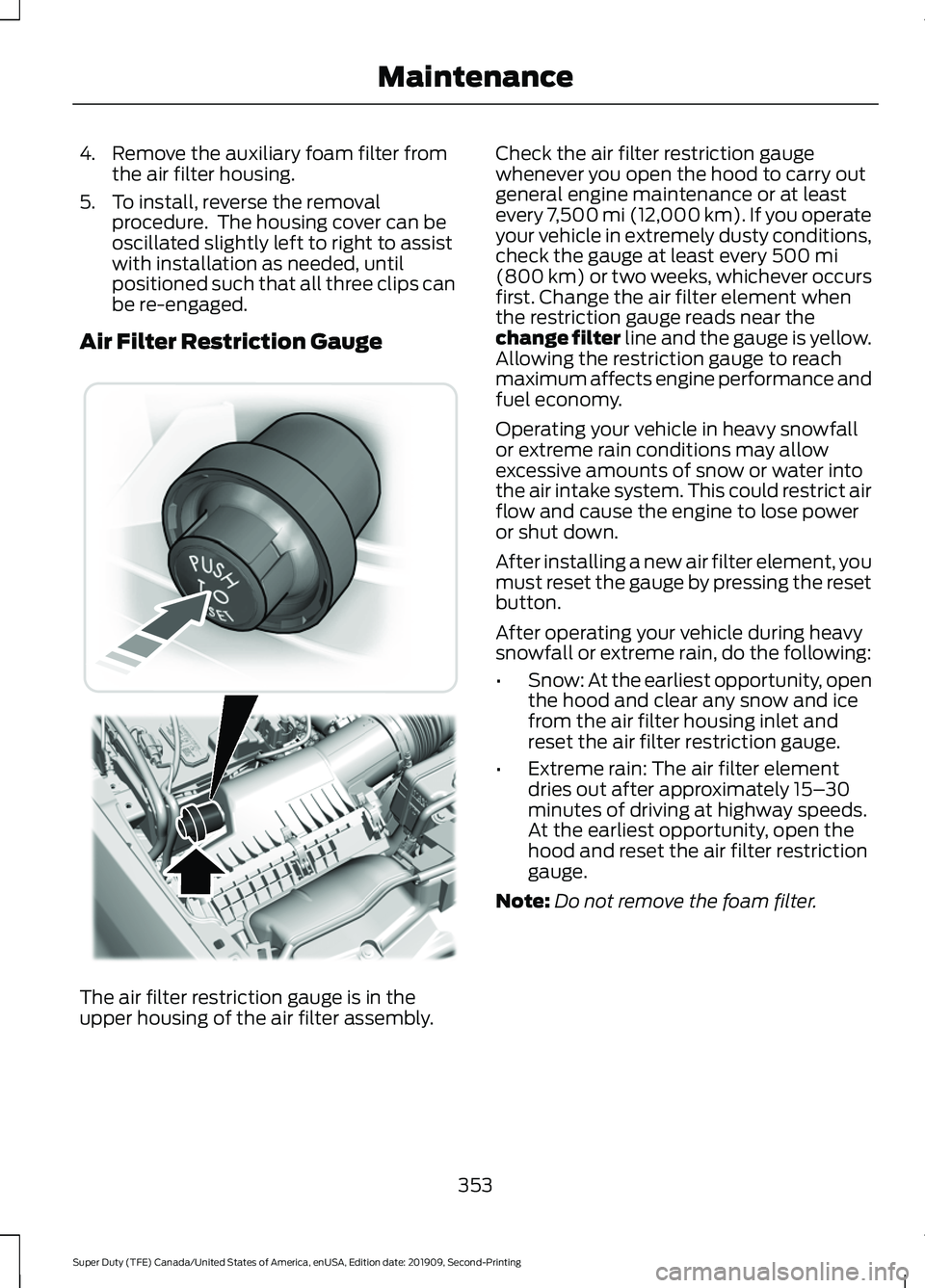
Air Filter Restriction Gauge The air filter restriction gauge is in the
upper housing of the air filter assembly. Check the air filter restriction gauge
whenever you open the hood to carry out
general engine maintenance or at least
every 7,500 mi (12,000 km). If you operate
your vehicle in extremely dusty conditions,
check the gauge at least every 500 mi
(800 km) or two weeks, whichever occurs
first. Change the air filter element when
the restriction gauge reads near the
change filter line and the gauge is yellow.
Allowing the restriction gauge to reach
maximum affects engine performance and
fuel economy.
Operating your vehicle in heavy snowfall
or extreme rain conditions may allow
excessive amounts of snow or water into
the air intake system. This could restrict air
flow and cause the engine to lose power
or shut down.
After installing a new air filter element, you
must reset the gauge by pressing the reset
button.
After operating your vehicle during heavy
snowfall or extreme rain, do the following:
• Snow: At the earliest opportunity, open
the hood and clear any snow and ice
from the air filter housing inlet and
reset the air filter restriction gauge.
• Extreme rain: The air filter element
dries out after approximately 15– 30
minutes of driving at highway speeds.
At the earliest opportunity, open the
hood and reset the air filter restriction
gauge.
Note: Do not remove the foam filter.
353
Super Duty (TFE) Canada/United States of America, enUSA, Edition date: 201909, Second-Printing Maintenance E310420
Page 357 of 633
CHANGING THE ENGINE AIR
FILTER - 7.3L
WARNING: To reduce the risk of
vehicle damage and personal burn
injuries, do not start your engine with the
air cleaner removed and do not remove
it while the engine is running.
Note: Operating your vehicle in heavy
snowfall or extreme rain conditions may
allow excessive amounts of snow or water
into the air intake system. This could plug
or soak the air filter that could cause the
engine to lose power or shut down.
When replacing the air filter element, use
a Motorcraft® air filter element. See
Motorcraft Parts
(page 438).
Note: Failure to use the correct air filter
element may result in severe engine
damage. Resulting component damage
may not be covered by the vehicle Warranty.
Change the air filter element at the correct
interval. See
Scheduled Maintenance
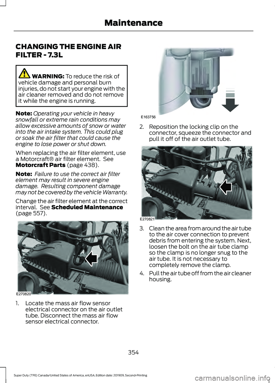
(page 557). 1. Locate the mass air flow sensor
electrical connector on the air outlet
tube. Disconnect the mass air flow
sensor electrical connector. 2. Reposition the locking clip on the
connector, squeeze the connector and
pull it off of the air outlet tube. 3.
Clean the area from around the air tube
to the air cover connection to prevent
debris from entering the system. Next,
loosen the bolt on the air tube clamp
so the clamp is no longer snug to the
air tube. It is not necessary to
completely remove the clamp.
4. Pull the air tube off from the air cleaner
housing.
354
Super Duty (TFE) Canada/United States of America, enUSA, Edition date: 201909, Second-Printing MaintenanceE270820 E163756 E270821
Page 358 of 633
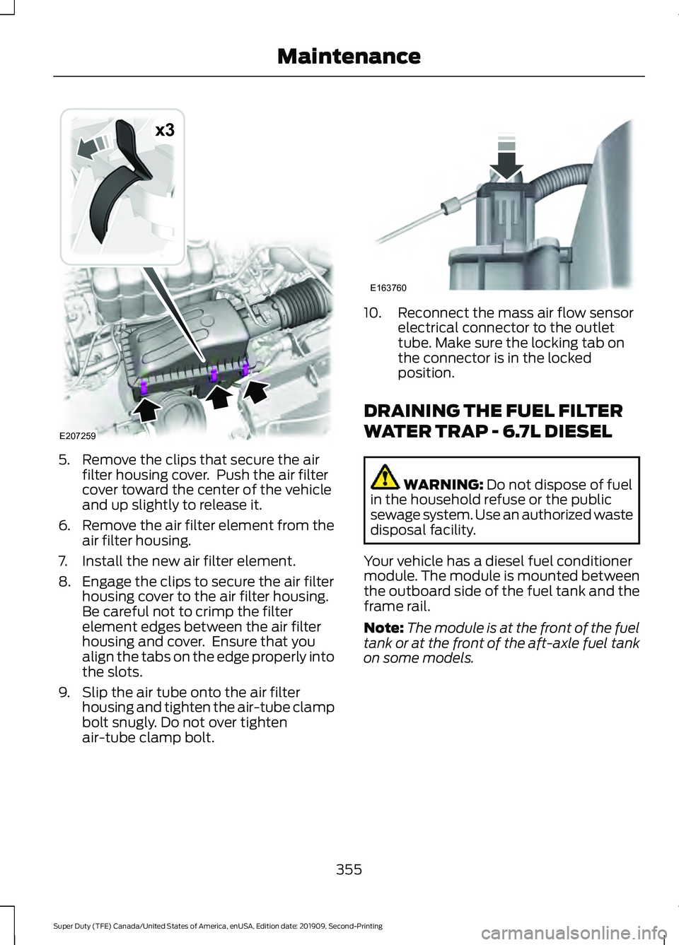
5. Remove the clips that secure the air
filter housing cover. Push the air filter
cover toward the center of the vehicle
and up slightly to release it.
6. Remove the air filter element from the
air filter housing.
7. Install the new air filter element.
8. Engage the clips to secure the air filter housing cover to the air filter housing.
Be careful not to crimp the filter
element edges between the air filter
housing and cover. Ensure that you
align the tabs on the edge properly into
the slots.
9. Slip the air tube onto the air filter housing and tighten the air-tube clamp
bolt snugly. Do not over tighten
air-tube clamp bolt. 10. Reconnect the mass air flow sensor
electrical connector to the outlet
tube. Make sure the locking tab on
the connector is in the locked
position.
DRAINING THE FUEL FILTER
WATER TRAP - 6.7L DIESEL WARNING: Do not dispose of fuel
in the household refuse or the public
sewage system. Use an authorized waste
disposal facility.
Your vehicle has a diesel fuel conditioner
module. The module is mounted between
the outboard side of the fuel tank and the
frame rail.
Note: The module is at the front of the fuel
tank or at the front of the aft-axle fuel tank
on some models.
355
Super Duty (TFE) Canada/United States of America, enUSA, Edition date: 201909, Second-Printing MaintenanceE207259
x3 E163760
Page 359 of 633
You should drain water from the
module assembly whenever the
warning light illuminates or a
message appears in the information
display advising you to drain the water
separator. This occurs when approximately
6.76 fl oz (200 ml) of water accumulates
in the module. If you allow the water level to exceed this level, the water may pass
through to the engine and may cause fuel
injection equipment damage.
Filter Location
Use the tables below to find the location
of your filter.
Pick-up Truck Filter Location
Box Length
Cab Type
Left side of fuel tank.
8 ft (2.4 m)
Regular.
6.75 ft (2.057 m)
SuperCab.
In front of fuel tank.
8 ft (2.4 m)
6.75 ft (2.057 m)
Super Crew Cab.
Left side of fuel tank.
8 ft (2.4 m)
Chassis Cab Filter Location
Fuel Tank Type
Cab Type
Right side of fuel tank.
Single midship fuel tank
Chassis Cab.
Right side of midship fueltank.
Aft axle/midship fuel tanks
Chassis Cab.
Front of fuel tank.
Single aft axle fuel tank
Chassis Cab.
Draining the Diesel Fuel
Conditioner Module
1. Switch the engine off.
2. Access the underside of your vehicle.
356
Super Duty (TFE) Canada/United States of America, enUSA, Edition date: 201909, Second-Printing Maintenance
Page 360 of 633
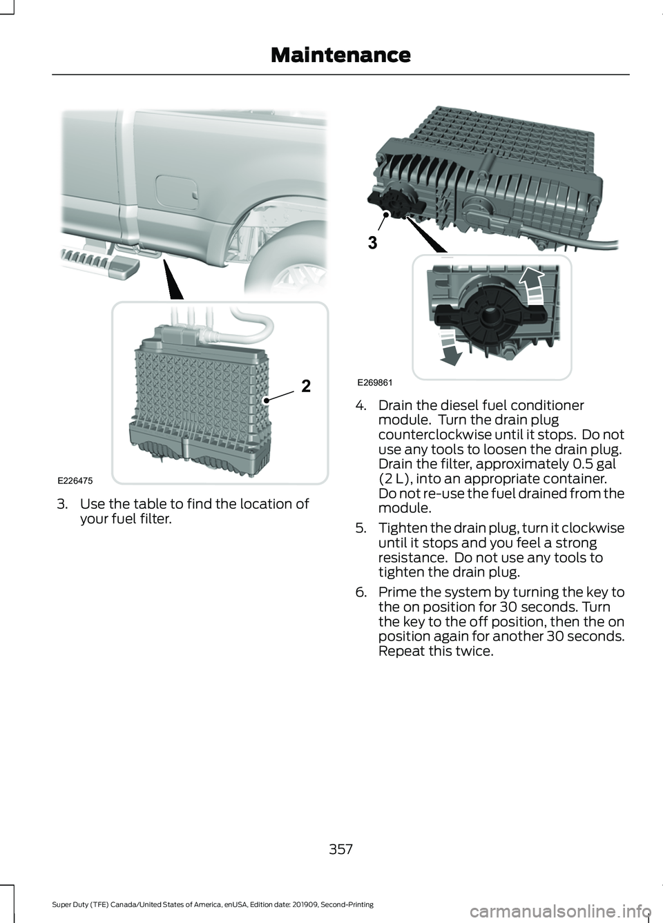
3. Use the table to find the location of
your fuel filter. 4. Drain the diesel fuel conditioner
module. Turn the drain plug
counterclockwise until it stops. Do not
use any tools to loosen the drain plug.
Drain the filter, approximately 0.5 gal
(2 L), into an appropriate container.
Do not re-use the fuel drained from the
module.
5. Tighten the drain plug, turn it clockwise
until it stops and you feel a strong
resistance. Do not use any tools to
tighten the drain plug.
6. Prime the system by turning the key to
the on position for 30 seconds. Turn
the key to the off position, then the on
position again for another 30 seconds.
Repeat this twice.
357
Super Duty (TFE) Canada/United States of America, enUSA, Edition date: 201909, Second-Printing MaintenanceE226475
2 E269861