display FORD F450 2015 Workshop Manual
[x] Cancel search | Manufacturer: FORD, Model Year: 2015, Model line: F450, Model: FORD F450 2015Pages: 485, PDF Size: 5.35 MB
Page 178 of 485
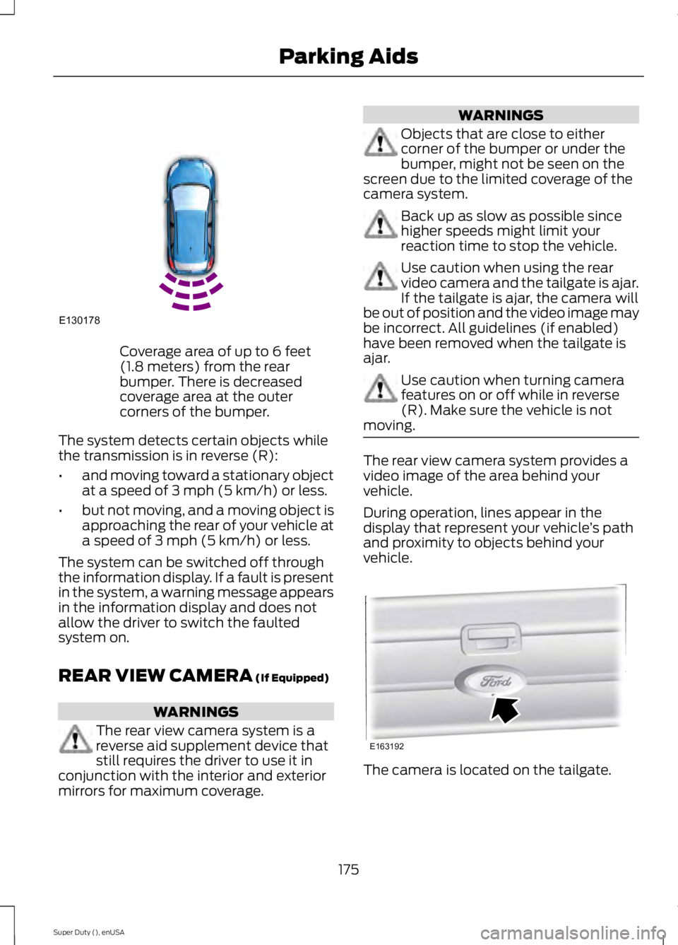
Coverage area of up to 6 feet
(1.8 meters) from the rear
bumper. There is decreased
coverage area at the outer
corners of the bumper.
The system detects certain objects while
the transmission is in reverse (R):
• and moving toward a stationary object
at a speed of 3 mph (5 km/h) or less.
• but not moving, and a moving object is
approaching the rear of your vehicle at
a speed of
3 mph (5 km/h) or less.
The system can be switched off through
the information display. If a fault is present
in the system, a warning message appears
in the information display and does not
allow the driver to switch the faulted
system on.
REAR VIEW CAMERA
(If Equipped) WARNINGS
The rear view camera system is a
reverse aid supplement device that
still requires the driver to use it in
conjunction with the interior and exterior
mirrors for maximum coverage. WARNINGS
Objects that are close to either
corner of the bumper or under the
bumper, might not be seen on the
screen due to the limited coverage of the
camera system. Back up as slow as possible since
higher speeds might limit your
reaction time to stop the vehicle.
Use caution when using the rear
video camera and the tailgate is ajar.
If the tailgate is ajar, the camera will
be out of position and the video image may
be incorrect. All guidelines (if enabled)
have been removed when the tailgate is
ajar. Use caution when turning camera
features on or off while in reverse
(R). Make sure the vehicle is not
moving. The rear view camera system provides a
video image of the area behind your
vehicle.
During operation, lines appear in the
display that represent your vehicle
’s path
and proximity to objects behind your
vehicle. The camera is located on the tailgate.
175
Super Duty (), enUSA Parking AidsE130178 E163192
Page 179 of 485
Using the Rear View Camera
System
The rear view camera system displays
what is behind your vehicle when you place
the transmission in reverse (R).
The system uses two types of guides to
help you see what is behind your vehicle:
•
Fixed guidelines: Show the actual path
your vehicle is moving in while reversing
in a straight line. This can be helpful
when backing into a parking space or
aligning your vehicle with another
object behind you.
• Centerline: Helps align the center of
your vehicle with an object (for
example, a trailer).
Note: The image may remain on
momentarily when you shift the
transmission out of reverse (R). If your
vehicle speed reaches 6 mph (10 km/h) or
10 seconds elapse and the image remains
on, have your system inspected by an
authorized dealer.
Note: When towing, the camera only sees
what you are towing behind your vehicle.
This might not provide adequate coverage
as it usually provides in normal operation
and you might not see some objects. In
some vehicles, the guidelines may disappear
once you engage the trailer tow connector.
The camera may not operate correctly
under the following conditions:
• Nighttime or dark areas if the reverse
lamps are not operating.
• Mud, water or debris obstructs the
camera's view. Clean the lens with a
soft, lint-free cloth and non-abrasive
cleaner.
• The camera is misaligned due to
damage to the rear of your vehicle. To access any of the rear view camera
system settings, make the following
selections in the display screen when the
transmission is not in reverse (R):
•
Menu > Vehicle > Camera Settings
After changing a system setting, the touch
screen shows a preview of the selected
features.
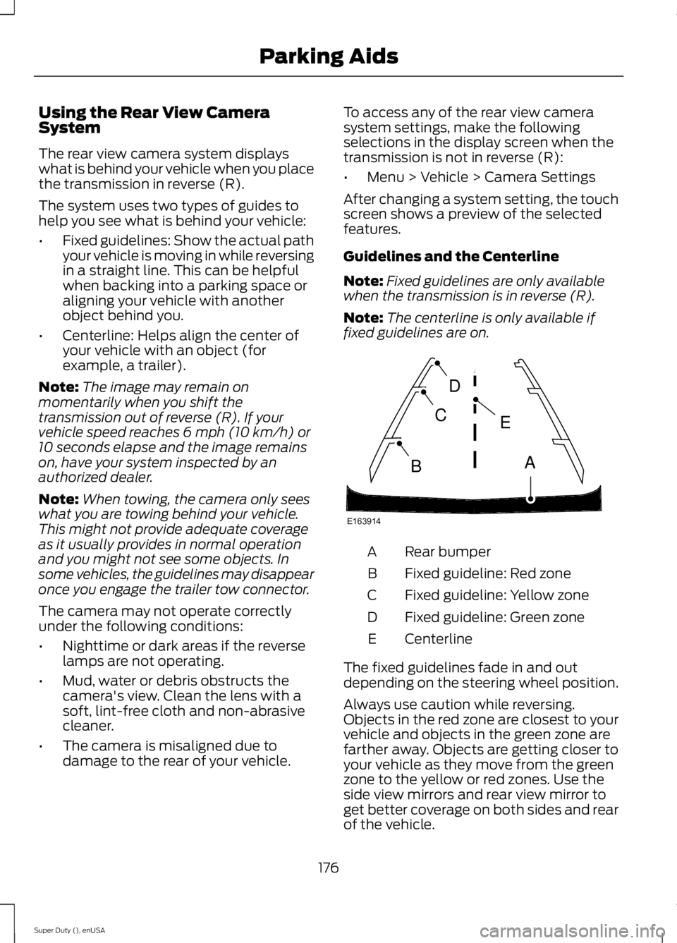
Guidelines and the Centerline
Note: Fixed guidelines are only available
when the transmission is in reverse (R).
Note: The centerline is only available if
fixed guidelines are on. Rear bumper
A
Fixed guideline: Red zone
B
Fixed guideline: Yellow zone
C
Fixed guideline: Green zone
D
Centerline
E
The fixed guidelines fade in and out
depending on the steering wheel position.
Always use caution while reversing.
Objects in the red zone are closest to your
vehicle and objects in the green zone are
farther away. Objects are getting closer to
your vehicle as they move from the green
zone to the yellow or red zones. Use the
side view mirrors and rear view mirror to
get better coverage on both sides and rear
of the vehicle.
176
Super Duty (), enUSA Parking AidsE163914
A
E
D
C
B
Page 180 of 485
Enhanced Park Aids
Note:
Enhanced park aids is only available
when the transmission is in reverse (R).
Note: The reverse sensing system is not
effective at speeds above 3 mph (5 km/h)
and may not detect certain angular or
moving objects.
The system uses red, yellow and green
highlights which appear on top of the video
image when an object is detected by the
reverse sensing system. The alert highlights
the closest object detected. The reverse
sensing alert can be disabled and if visual
park aid alert is enabled, highlighted areas
are still displayed.
Selectable settings for this feature are ON
and OFF.
Rear Camera Delay
When shifting the transmission out of
reverse (R) and into any gear other than
park (P), the camera image remains in the
display until your vehicle speed reaches
6 mph (10 km/h)
or 10 seconds elapses.
This occurs when the rear camera delay
feature is ON.
Selectable settings for this feature are ON
and OFF. The default setting for the rear
camera delay is OFF.
177
Super Duty (), enUSA Parking Aids
Page 195 of 485
RV & Trailer Towing Guide Online
http://www.fleet.ford.com/towing-guides/
Website
TRAILER SWAY CONTROL (If
Equipped) WARNING
Turning off trailer sway control
increases the risk of loss of vehicle
control, serious injury or death. Ford
does not recommend disabling this feature
except in situations where speed reduction
may be detrimental (such as hill climbing),
the driver has significant trailer towing
experience, and can control trailer sway
and maintain safe operation. Note:
This feature does not prevent trailer
sway, but reduces it once it begins.
Note: This feature cannot stop all trailers
from swaying.
Note: In some cases, if vehicle speed is too
high, the system may activate multiple
times, gradually reducing vehicle speed.
This feature applies your vehicle brakes at
individual wheels and, if necessary, reduces
engine power. If the trailer begins to sway,
the stability control light flashes and the
message
TRAILER SWAY REDUCE
SPEED appears in the information display.
The first thing to do is slow your vehicle
down, then pull safely to the side of the
road and check for proper tongue load and
trailer load distribution. See
Load
Carrying (page 180). RECOMMENDED TOWING
WEIGHTS
Note:
Do not exceed a trailer
weight of 5000 pounds (2268
kilograms) when towing with, or
by, bumper only.
Note: Make sure to take into
consideration trailer frontal area.
Do not exceed 60 feet 2
(5.6
meters 2
) trailer frontal area.
Note: Exceeding this limitation
may significantly reduce the
performance of your towing
vehicle. Selecting a trailer with a
low aerodynamic drag and rounded
front design helps optimize
performance and fuel economy.
Note: For high altitude operation,
reduce the gross combined weight
by 2% per 1000 feet (300 meters)
starting at the 1000 foot (300
meter) elevation point.
Note: Certain states require
electric trailer brakes for trailers
over a specified weight. Be sure to
check state regulations for this
specified weight. The maximum
trailer weights listed may be limited
to this specified weight, as your
vehicle's electrical system may not
include the wiring connector
needed to use electric trailer
brakes.
192
Super Duty (), enUSA Towing
Page 199 of 485
Remember to account for the trailer
tongue weight as part of your vehicle load
when calculating the total vehicle weight.
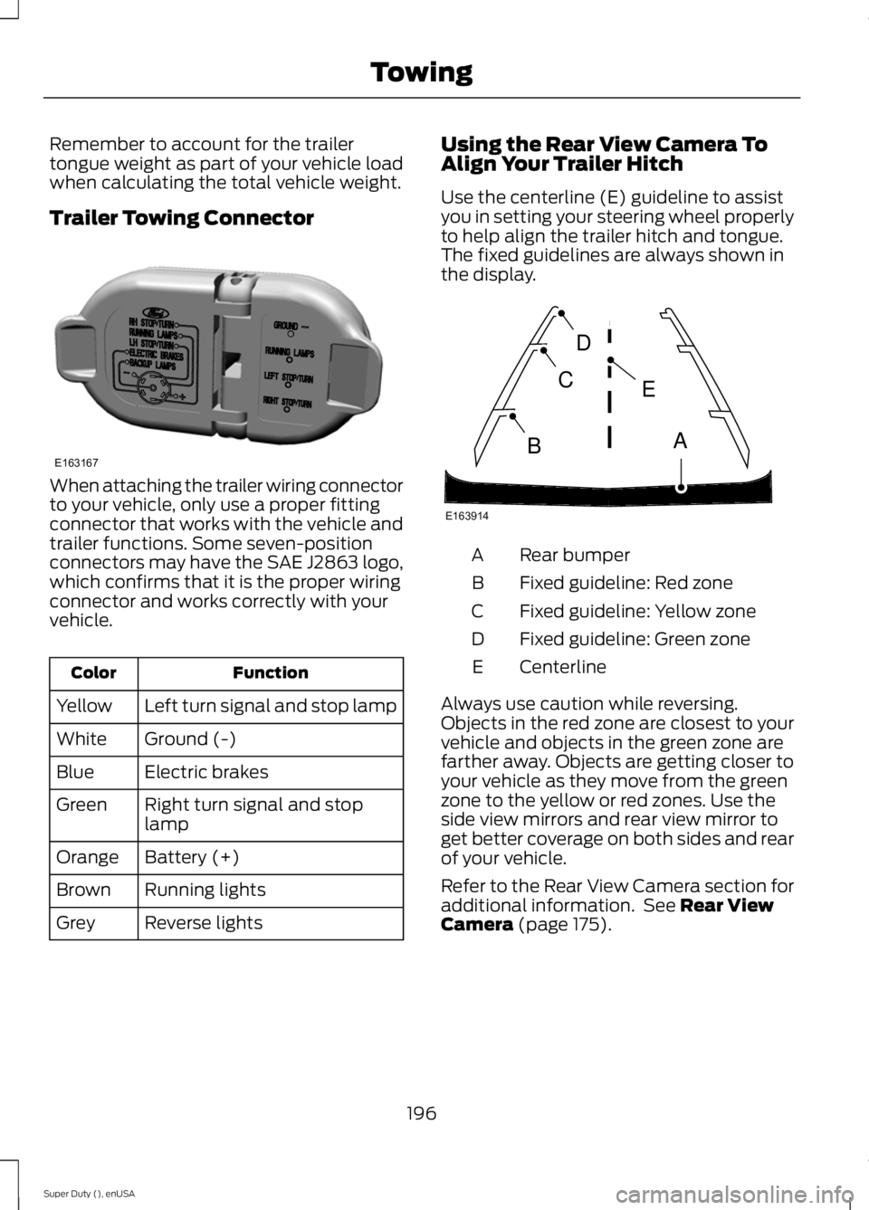
Trailer Towing Connector
When attaching the trailer wiring connector
to your vehicle, only use a proper fitting
connector that works with the vehicle and
trailer functions. Some seven-position
connectors may have the SAE J2863 logo,
which confirms that it is the proper wiring
connector and works correctly with your
vehicle.
Function
Color
Left turn signal and stop lamp
Yellow
Ground (-)
White
Electric brakes
Blue
Right turn signal and stop
lamp
Green
Battery (+)
Orange
Running lights
Brown
Reverse lights
Grey Using the Rear View Camera To
Align Your Trailer Hitch
Use the centerline (E) guideline to assist
you in setting your steering wheel properly
to help align the trailer hitch and tongue.
The fixed guidelines are always shown in
the display.
Rear bumper
A
Fixed guideline: Red zone
B
Fixed guideline: Yellow zone
C
Fixed guideline: Green zone
D
Centerline
E
Always use caution while reversing.
Objects in the red zone are closest to your
vehicle and objects in the green zone are
farther away. Objects are getting closer to
your vehicle as they move from the green
zone to the yellow or red zones. Use the
side view mirrors and rear view mirror to
get better coverage on both sides and rear
of your vehicle.
Refer to the Rear View Camera section for
additional information. See Rear View
Camera (page 175).
196
Super Duty (), enUSA TowingE163167 E163914
A
E
D
C
B
Page 202 of 485
When used properly, the trailer brake
controller assists in smooth and effective
trailer braking by powering the trailer
’s
electric or electric-over-hydraulic brakes
with a proportional output based on the
towing vehicle ’s brake pressure.
You can adjust the amount of initial trailer
brake output by selecting one of three
settings through the message center.
Ford has tested the trailer brake controller
to be compatible with several major
brands of electric-over-hydraulic trailer
brakes. Contact an authorized dealer for
information on which brands you can use.
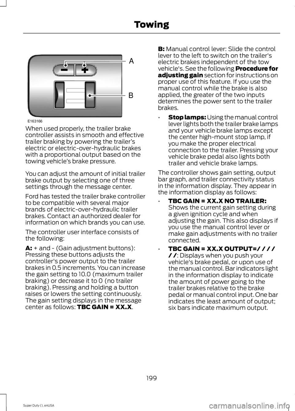
The controller user interface consists of
the following:
A: + and - (Gain adjustment buttons):
Pressing these buttons adjusts the
controller's power output to the trailer
brakes in 0.5 increments. You can increase
the gain setting to 10.0 (maximum trailer
braking) or decrease it to 0 (no trailer
braking). Pressing and holding a button
raises or lowers the setting continuously.
The gain setting displays in the message
center as follows:
TBC GAIN = XX.X. B:
Manual control lever: Slide the control
lever to the left to switch on the trailer's
electric brakes independent of the tow
vehicle's. See the following Procedure for
adjusting gain section for instructions on
proper use of this feature. If you use the
manual control while the brake is also
applied, the greater of the two inputs
determines the power sent to the trailer
brakes.
• Stop lamps: Using the manual control
lever lights both the trailer brake lamps
and your vehicle brake lamps except
the center high-mount stop lamp, if
you make the proper electrical
connection to the trailer. Pressing your
vehicle brake pedal also lights both
trailer and vehicle brake lamps.
The controller shows gain setting, output
bar graph, and trailer connectivity status
in the information display. They appear in
the information display as follows:
• TBC GAIN = XX.X NO TRAILER:
Shows the current gain setting during
a given ignition cycle and when
adjusting the gain. This also displays if
you use the manual control lever or
make gain adjustments with no trailer
connected.
• TBC GAIN = XX.X OUTPUT=/ / / /
/ /
: Displays when you push your
vehicle's brake pedal, or upon use of
the manual control. Bar indicators light
in the information display to indicate
the amount of power going to the
trailer brakes relative to the brake
pedal or manual control input. One bar
indicates the least amount of output;
six bars indicate maximum output.
199
Super Duty (), enUSA TowingB
A
E163166
Page 203 of 485
•
TRAILER CONNECTED: Displays
when the system senses a correct
trailer wiring connection during a given
ignition cycle.
• TRAILER DISCONNECTED:
Displays,
accompanied by a single audible time,
when the system senses a trailer
connection and then a disconnection,
either intentional or unintentional,
during a given ignition cycle. It also
displays if a truck or trailer-wiring fault
occurs causing the trailer to appear
disconnected. This message can also
display if you use the manual control
lever without a trailer connected.
Procedure for Adjusting Gain
Note: Only perform this procedure in a
traffic-free environment at speeds of
approximately 20-25 mph (30-40 km/h).
The gain setting sets the trailer brake
controller for the specific towing condition.
You should change the setting as towing
conditions change. Changes to towing
conditions include trailer load, vehicle load,
road conditions and weather.
The gain should be set to provide the
maximum trailer braking assistance while
making sure the trailer wheels do not lock
when using the brakes. Locked trailer
wheels may lead to trailer instability.
1. Make sure the trailer brakes are in good
working condition, functioning normally
and properly adjusted. See your trailer
dealer if necessary.
2. Hook up the trailer and make the electrical connections according to the
trailer manufacturer's instructions.
3. When you plug in a trailer with electric or electric-over-hydraulic brakes,
TRAILER CONNECTED
appears in
the information display. 4. Use the gain adjustment (+ and -)
buttons to increase or decrease the
gain setting to the desired starting
point. A gain setting of 6.0 is a good
starting point for heavier loads.
5. In a traffic-free environment, tow the trailer on a dry, level surface at a speed
of 20-25 mph (30-40 km/h) and
squeeze the manual control lever
completely.
6. If the trailer wheels lock up, indicated by squealing tires, reduce the gain
setting. If the trailer wheels turn freely,
increase the gain setting. Repeat Steps
5 and 6 until the gain setting is at a
point just below trailer wheel lock-up.
If towing a heavier trailer, trailer wheel
lock-up may not be attainable even
with the maximum gain setting of 10.
Initial Output Setting
The trailer brake controller lets you
customize how aggressively the trailer
brakes engage. The default value is set to
“Light” . We recommend this setting for the
majority of trailers. If you are using an EOH
trailer with a high setting voltage, or if you
prefer to feel more brake feedback from
the trailer, then select “Medium” or
“Heavy ”.
Trailer Brake Effort Setting
The trailer brake controller allows the user
to customize how aggressively the trailer
brakes engage. The default value is "Low"
and is the recommended setting for most
trailers. If your trailer's brakes require more
initial voltage, or if you prefer more
aggressive trailer braking, then select either
the "Medium" or the "High" setting.
200
Super Duty (), enUSA Towing
Page 204 of 485
Information Display Warning Messages
Note:
An authorized dealer can diagnose
the trailer brake controller to determine
exactly which trailer fault has occurred.
However, your Ford warranty does not cover
this diagnosis if the fault is with the trailer.
TRAILER BRAKE MODULE FAULT
Displays in response to faults sensed by
the trailer brake controller, accompanied
by a single tone. If this message appears,
contact an authorized dealer as soon as
possible for diagnosis and repair. The
controller may still function, but with
degraded performance.
WIRING FAULT ON TRAILER
Displays when there is a short circuit on
the electric brake output wire.
If this message displays, accompanied by
a single tone, with no trailer connected, the
problem is with your vehicle wiring
between the trailer brake controller and
the 7-pin connector at the bumper.
If the message only displays with a trailer
connected, the problem is with the trailer
wiring. Consult your trailer dealer for
assistance. This can be a short to ground
(such as a chaffed wire), short to voltage
(such as a pulled pin on trailer emergency
breakaway battery) or the trailer brakes
may be drawing too much current.
Points to Remember
Note: Do not attempt removal of the trailer
brake controller without consulting the
Workshop Manual. Damage to the unit may
result. •
Adjust gain setting before using the
trailer brake controller for the first time.
• Adjust gain setting, using the procedure
above, whenever road, weather and
trailer or vehicle loading conditions
change from when the gain was initially
set.
• Only use the manual control lever for
proper adjustment of the gain during
trailer setup. Misuse, such as
application during trailer sway, could
cause instability of trailer or tow
vehicle.
• Avoid towing in adverse weather
conditions. The trailer brake controller
does not provide anti-lock control of
the trailer wheels. Trailer wheels can
lock up on slippery surfaces, resulting
in reduced stability of trailer and tow
vehicle.
• The trailer brake controller is equipped
with a feature that reduces output at
vehicle speeds below 11 mph (18 km/h)
so trailer and vehicle braking is not jerky
or harsh. This feature is only available
when applying the brakes using your
vehicle's brake pedal, not the
controller.
• The controller interacts with the brake
control system and powertrain control
system of your vehicle to provide the
best performance on different road
conditions.
• Your vehicle's brake system and the
trailer brake system work
independently of each other. Changing
the gain setting on the controller does
not affect the operation of your
vehicle's brakes whether you attach a
trailer or not.
201
Super Duty (), enUSA Towing
Page 205 of 485
•
When you switch the engine off, the
controller output is disabled and the
display and module shut down. The
controller module and display turn on
when you switch the ignition on.
• The trailer brake controller is only a
factory-installed or dealer-installed
item. Ford is not responsible for
warranty or performance of the
controller due to misuse or customer
installation.
Trailer Lamps WARNING
Never connect any trailer lamp wiring
to the vehicle's tail lamp wiring; this
may damage the electrical system
resulting in fire. Contact your authorized
dealer as soon as possible for assistance
in proper trailer tow wiring installation.
Additional electrical equipment may be
required. Trailer lamps are required on most towed
vehicles. Make sure all running lights, brake
lights, turn signals and hazard lights are
working.
Using a Step Bumper (If Equipped)
The rear bumper is equipped with an
integral hitch and only requires a ball with
a one-inch (25.4 millimeter) shank
diameter. The bumper has a 5000-pound
(2268 kilogram) trailer weight and a
500-pound (227 kilogram) tongue weight
capacity
If it is necessary to relocate the hitch ball
position, you must install a frame-mounted
trailer hitch. Before Towing a Trailer
Practice turning, stopping and backing up
to get the feel of your vehicle-trailer
combination before starting on a trip.
When turning, make wider turns so the
trailer wheels clear curbs and other
obstacles.
When Towing a Trailer
•
Do not drive faster than 70 mph (113
km/h) during the first 500 miles (800
kilometers).
• Do not make full-throttle starts.
• Check your hitch, electrical connections
and trailer wheel lug nuts thoroughly
after you have traveled 50 miles (80
kilometers).
• When stopped in congested or heavy
traffic during hot weather, place the
gearshift in position P to aid engine and
transmission cooling and to help A/C
performance.
• Turn off the speed control with heavy
loads or in hilly terrain. The speed
control may turn off automatically
when you are towing on long, steep
grades.
• Shift to a lower gear when driving down
a long or steep hill. Do not apply the
brakes continuously, as they may
overheat and become less effective.
• If your transmission is equipped with a
Grade Assist or Tow/Haul feature, use
this feature when towing. This provides
engine braking and helps eliminate
excessive transmission shifting for
optimum fuel economy and
transmission cooling.
202
Super Duty (), enUSA Towing
Page 242 of 485
You have limited engine power when in the
fail-safe mode, so drive the vehicle with
caution. The vehicle will not be able to
maintain high-speed operation and the
engine will run rough. Remember that the
engine is capable of completely shutting
down automatically to prevent engine
damage, therefore:
1. Pull off the road as soon as safely
possible and turn off the engine.
2. Arrange for the vehicle to be taken to an authorized dealer.
3. If this is not possible, wait a short period for the engine to cool.
4. Check the coolant level and replenish if low.
5. Re-start the engine and take your vehicle to an authorized dealer.
Note: Driving the vehicle without repairing
the engine problem increases the chance of
engine damage. Take your vehicle to an
authorized dealer as soon as possible.
Engine Fluid Temperature
Management (If Equipped) WARNINGS
To reduce the risk of collision and
injury, be prepared that the vehicle
speed may reduce and the vehicle
may not be able to accelerate with full
power until the fluid temperatures reduce. Never remove the coolant reservoir
cap while the engine is running or hot.
Your vehicle has been designed to pull a
trailer, but because of the added load, the
vehicle
’s engine may temporarily reach
higher temperatures during severe
operating conditions such as ascending a
long or steep grade while pulling a trailer
in hot ambient temperatures. At this time, you may notice your engine
coolant temperature gauge needle move
toward the H and the POWER REDUCED
TO LOWER TEMP message may appear
in the information display.
You may notice a reduction in the vehicle
’s
speed caused by reduced engine power.
In order to manage the engine fluid
temperatures, your vehicle may enter this
mode if certain high-temperature and
high-load conditions take place. The
amount of speed reduction will depend on
the vehicle loading, towing, grade, ambient
temperature, and other factors. If this
occurs, there is no need to pull off the road.
The vehicle can continue to be driven while
this message is active
The air conditioning may turn on and off
during severe operating conditions to
protect the engine from overheating. When
the engine coolant temperature decreases
to a more normal operating temperature,
the air conditioning will turn on once again.
If the engine coolant temperature gauge
moves fully into the red (hot) area, or if the
coolant temperature warning or service
engine soon messages appear in your
information display:
1. Stop your vehicle as soon as safely possible and shift the transmission into
Park (P).
2. Leave the engine running until the coolant temperature gauge needle
moves away from the H range. After
several minutes, if this does not
happen, follow the remaining steps.
3. Switch the engine off and wait for it to
cool before checking the coolant level.
4. If the coolant level is normal, you may restart your engine and continue on.
239
Super Duty (), enUSA Maintenance