FORD F550 2012 Owners Manual
Manufacturer: FORD, Model Year: 2012, Model line: F550, Model: FORD F550 2012Pages: 448, PDF Size: 6.01 MB
Page 331 of 448
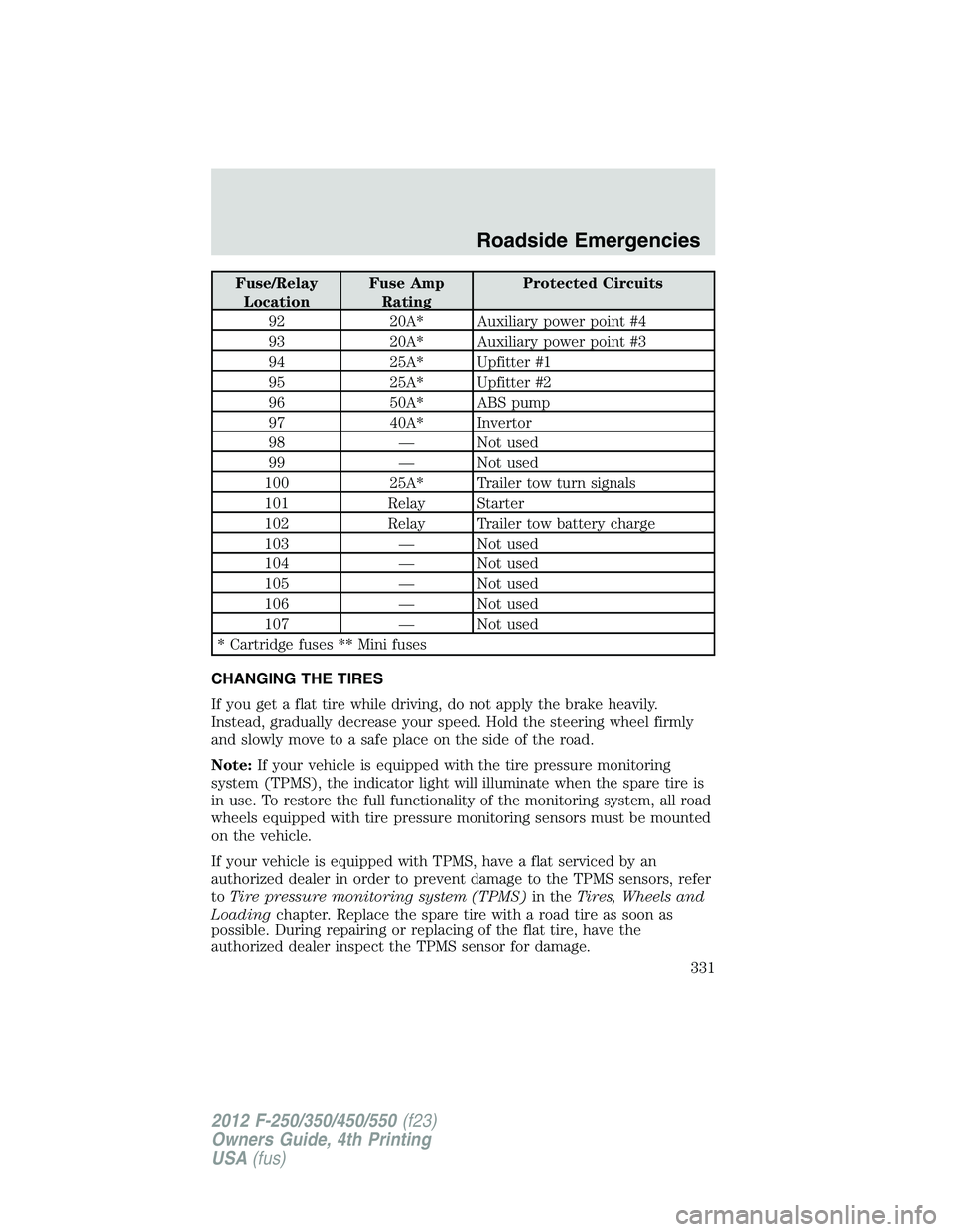
Fuse/Relay
Location Fuse Amp
Rating Protected Circuits
92 20A* Auxiliary power point #4
93 20A* Auxiliary power point #3
94 25A* Upfitter #1
95 25A* Upfitter #2
96 50A* ABS pump
97 40A* Invertor
98 — Not used
99 — Not used
100 25A* Trailer tow turn signals
101 Relay Starter
102 Relay Trailer tow battery charge
103 — Not used
104 — Not used
105 — Not used
106 — Not used
107 — Not used
* Cartridge fuses ** Mini fuses
CHANGING THE TIRES
If you get a flat tire while driving, do not apply the brake heavily.
Instead, gradually decrease your speed. Hold the steering wheel firmly
and slowly move to a safe place on the side of the road.
Note: If your vehicle is equipped with the tire pressure monitoring
system (TPMS), the indicator light will illuminate when the spare tire is
in use. To restore the full functionality of the monitoring system, all road
wheels equipped with tire pressure monitoring sensors must be mounted
on the vehicle.
If your vehicle is equipped with TPMS, have a flat serviced by an
authorized dealer in order to prevent damage to the TPMS sensors, refer
to Tire pressure monitoring system (TPMS) in the Tires, Wheels and
Loading chapter. Replace the spare tire with a road tire as soon as
possible. During repairing or replacing of the flat tire, have the
authorized dealer inspect the TPMS sensor for damage. Roadside Emergencies
331
2012 F-250/350/450/550 (f23)
Owners Guide, 4th Printing
USA (fus)
Page 332 of 448
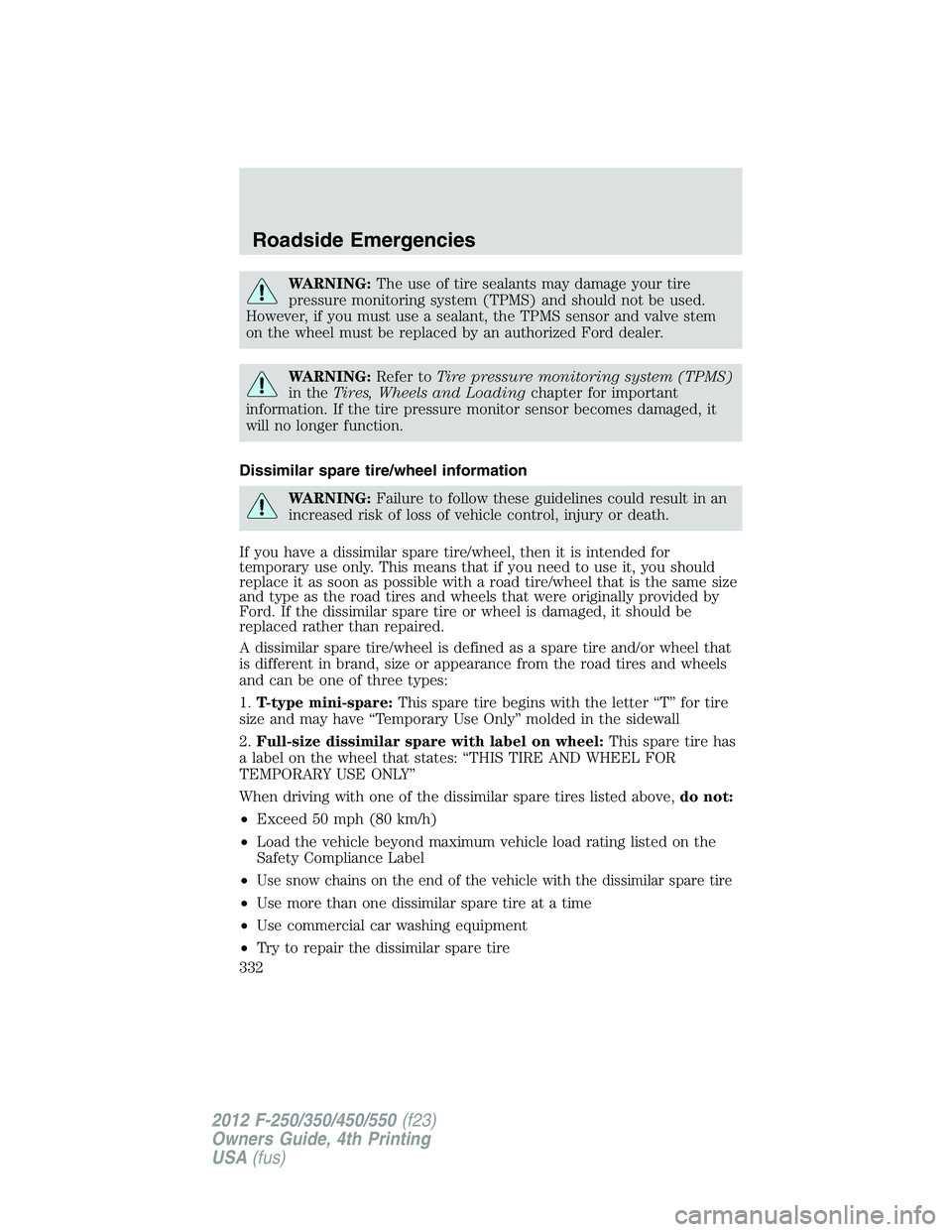
WARNING: The use of tire sealants may damage your tire
pressure monitoring system (TPMS) and should not be used.
However, if you must use a sealant, the TPMS sensor and valve stem
on the wheel must be replaced by an authorized Ford dealer.
WARNING: Refer to Tire pressure monitoring system (TPMS)
in the Tires, Wheels and Loading chapter for important
information. If the tire pressure monitor sensor becomes damaged, it
will no longer function.
Dissimilar spare tire/wheel information
WARNING: Failure to follow these guidelines could result in an
increased risk of loss of vehicle control, injury or death.
If you have a dissimilar spare tire/wheel, then it is intended for
temporary use only. This means that if you need to use it, you should
replace it as soon as possible with a road tire/wheel that is the same size
and type as the road tires and wheels that were originally provided by
Ford. If the dissimilar spare tire or wheel is damaged, it should be
replaced rather than repaired.
A dissimilar spare tire/wheel is defined as a spare tire and/or wheel that
is different in brand, size or appearance from the road tires and wheels
and can be one of three types:
1. T-type mini-spare: This spare tire begins with the letter “T” for tire
size and may have “Temporary Use Only” molded in the sidewall
2. Full-size dissimilar spare with label on wheel: This spare tire has
a label on the wheel that states: “THIS TIRE AND WHEEL FOR
TEMPORARY USE ONLY”
When driving with one of the dissimilar spare tires listed above, do not:
• Exceed 50 mph (80 km/h)
• Load the vehicle beyond maximum vehicle load rating listed on the
Safety Compliance Label
• Use snow chains on the end of the vehicle with the dissimilar spare tire
• Use more than one dissimilar spare tire at a time
• Use commercial car washing equipment
• Try to repair the dissimilar spare tireRoadside Emergencies
332
2012 F-250/350/450/550 (f23)
Owners Guide, 4th Printing
USA (fus)
Page 333 of 448
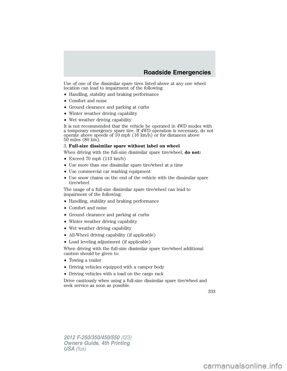
Use of one of the dissimilar spare tires listed above at any one wheel
location can lead to impairment of the following:
• Handling, stability and braking performance
• Comfort and noise
• Ground clearance and parking at curbs
• Winter weather driving capability
• Wet weather driving capability
It is not recommended that the vehicle be operated in 4WD modes with
a temporary emergency spare tire. If 4WD operation is necessary, do not
operate above speeds of 10 mph (16 km/h) or for distances above
50 miles (80 km).
3. Full-size dissimilar spare without label on wheel
When driving with the full-size dissimilar spare tire/wheel, do not:
• Exceed 70 mph (113 km/h)
• Use more than one dissimilar spare tire/wheel at a time
• Use commercial car washing equipment
• Use snow chains on the end of the vehicle with the dissimilar spare
tire/wheel
The usage of a full-size dissimilar spare tire/wheel can lead to
impairment of the following:
• Handling, stability and braking performance
• Comfort and noise
• Ground clearance and parking at curbs
• Winter weather driving capability
• Wet weather driving capability
• All-Wheel driving capability (if applicable)
• Load leveling adjustment (if applicable)
When driving with the full-size dissimilar spare tire/wheel additional
caution should be given to:
• Towing a trailer
• Driving vehicles equipped with a camper body
• Driving vehicles with a load on the cargo rack
Drive cautiously when using a full-size dissimilar spare tire/wheel and
seek service as soon as possible. Roadside Emergencies
333
2012 F-250/350/450/550 (f23)
Owners Guide, 4th Printing
USA (fus)
Page 334 of 448
Spare tire information
Note: If your vehicle is equipped the tire pressure monitoring system
(TPMS), the system indicator light will illuminate when the spare is in
use. To restore the full functionality of the TPMS system, all road wheels
equipped with the tire pressure monitoring sensors must be mounted on
the vehicle.
If your vehicle is equipped with TPMS, have a flat tire serviced by an
authorized dealer in order to prevent damage to the TPMS sensor; refer
to Tire Pressure Monitoring System (TPMS) in the Tires, Wheel and
Loading chapter. Replace the spare tire with the road tire as soon as
possible.
Stopping and securing the vehicle
WARNING: To help prevent the vehicle from moving when you
change a tire, be sure the parking brake is set, then block (in
both directions) the wheel that is diagonally opposite to the tire being
changed.
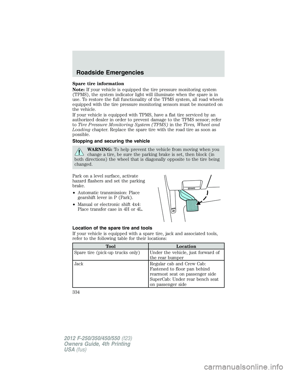
Park on a level surface, activate
hazard flashers and set the parking
brake.
• Automatic transmission: Place
gearshift lever in P (Park).
• Manual or electronic shift 4x4:
Place transfer case in 4H or 4L.
Location of the spare tire and tools
If your vehicle is equipped with a spare tire, jack and associated tools,
refer to the following table for their locations:
Tool Location
Spare tire (pick-up trucks only) Under the vehicle, just forward of
the rear bumper
Jack Regular cab and Crew Cab:
Fastened to floor pan behind
rearmost seat on passenger side
SuperCab: Under rear bench seat
on passenger sideRoadside Emergencies
334
2012 F-250/350/450/550 (f23)
Owners Guide, 4th Printing
USA (fus)
Page 335 of 448
![FORD F550 2012 Owners Manual Tool Location
Jack handle, lug wrench, lug
wrench extension (only available
on Dual Rear Wheel [DRW]
vehicles) and wheel chock (only
available on Single Rear Wheel
[SRW] vehicles equipped with a
diese FORD F550 2012 Owners Manual Tool Location
Jack handle, lug wrench, lug
wrench extension (only available
on Dual Rear Wheel [DRW]
vehicles) and wheel chock (only
available on Single Rear Wheel
[SRW] vehicles equipped with a
diese](/img/11/58801/w960_58801-334.png)
Tool Location
Jack handle, lug wrench, lug
wrench extension (only available
on Dual Rear Wheel [DRW]
vehicles) and wheel chock (only
available on Single Rear Wheel
[SRW] vehicles equipped with a
diesel engine) Regular cab: Fastened to floor
behind driver seat
SuperCab: Fastened to floor under
rear seat
Crew Cab: Fastened to floor
behind rear seat at driver side
Key and spare tire lock In the glove box
Removing the spare tire (with spare tire carrier only)
1. The following tools are required to remove the spare tire:
• one handle extension and two
typical extensions. To assemble,
align button with hole and slide
parts together. To disconnect,
depress button and pull apart.
• one wheel nut wrench. Slide over
square end of jack handle.
• Vehicles equipped with dual
rear wheels, insert the lug
wrench extension into the lug
wrench to reach the lug nuts. Roadside Emergencies
335
2012 F-250/350/450/550 (f23)
Owners Guide, 4th Printing
USA (fus)
Page 336 of 448
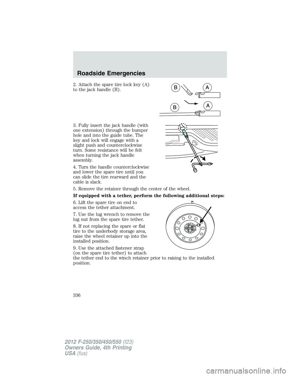
2. Attach the spare tire lock key (A)
to the jack handle (B).
3. Fully insert the jack handle (with
one extension) through the bumper
hole and into the guide tube. The
key and lock will engage with a
slight push and counterclockwise
turn. Some resistance will be felt
when turning the jack handle
assembly.
4. Turn the handle counterclockwise
and lower the spare tire until you
can slide the tire rearward and the
cable is slack.
5. Remove the retainer through the center of the wheel.
If equipped with a tether, perform the following additional steps:
6. Lift the spare tire on end to
access the tether attachment.
7. Use the lug wrench to remove the
lug nut from the spare tire tether.
8. If not replacing the spare or flat
tire to the underbody storage area,
raise the wheel retainer up into the
installed position.
9. Use the attached fastener strap
(on the spare tire tether) to attach
the tether end to the winch retainer prior to raising to the installed
position.Roadside Emergencies
336
2012 F-250/350/450/550 (f23)
Owners Guide, 4th Printing
USA (fus)
Page 337 of 448
Tire change procedure
WARNING: When one of the rear wheels is off the ground, the
transmission alone will not prevent the vehicle from moving or
slipping off the jack, even if the transmission is in P (Park).
WARNING: To prevent the vehicle from moving when you
change a tire, be sure the parking brake is set, then block (in
both directions) the wheel that is diagonally opposite (other side and
end of the vehicle) to the tire being changed.
WARNING: If the vehicle slips off the jack, you or someone else
could be seriously injured.
WARNING: Do not attempt to change a tire on the side of the
vehicle close to moving traffic. Pull far enough off the road to
avoid the danger of being hit when operating the jack or changing the
wheel.
Note: Passengers should not remain in the vehicle when the vehicle is
being jacked.
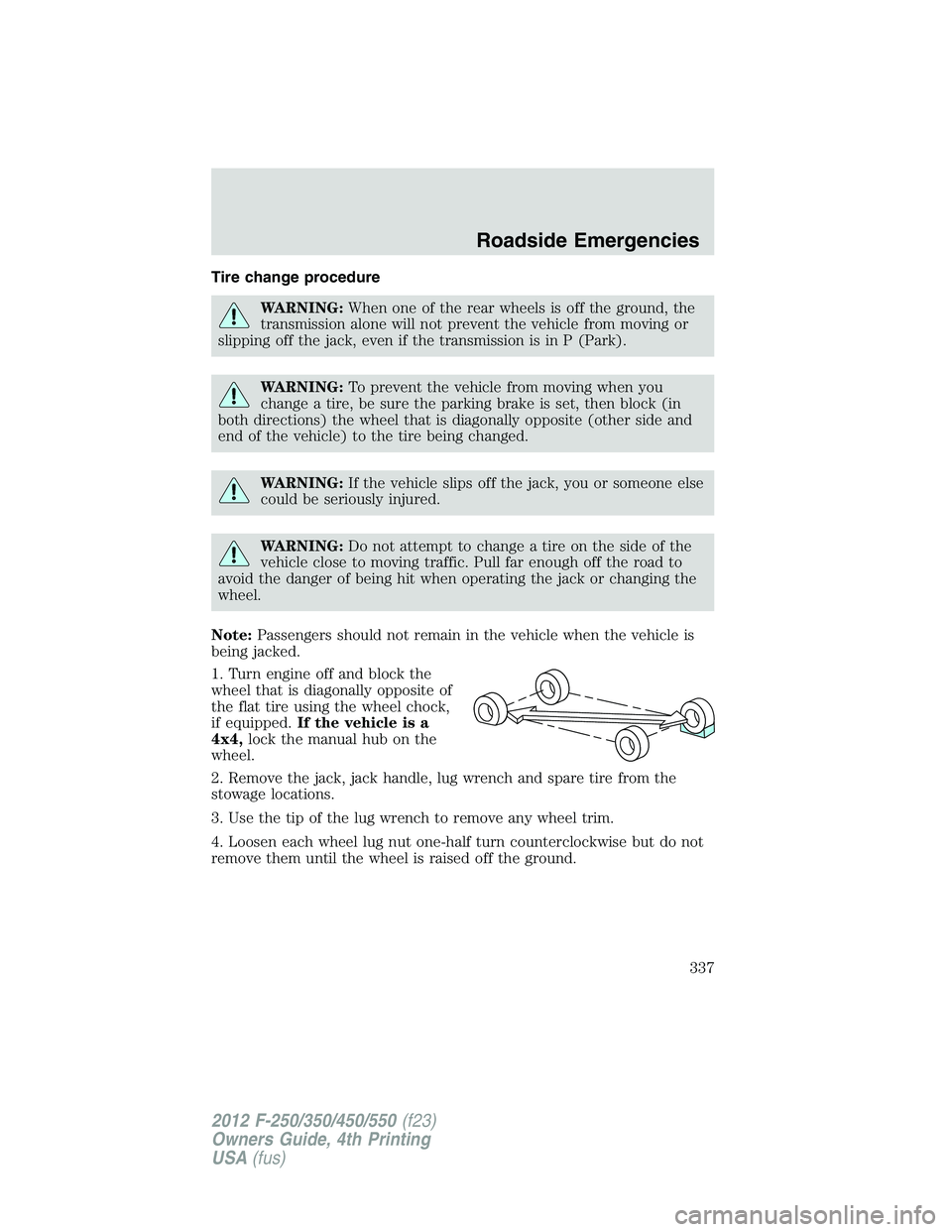
1. Turn engine off and block the
wheel that is diagonally opposite of
the flat tire using the wheel chock,
if equipped. If the vehicle is a
4x4, lock the manual hub on the
wheel.
2. Remove the jack, jack handle, lug wrench and spare tire from the
stowage locations.
3. Use the tip of the lug wrench to remove any wheel trim.
4. Loosen each wheel lug nut one-half turn counterclockwise but do not
remove them until the wheel is raised off the ground. Roadside Emergencies
337
2012 F-250/350/450/550 (f23)
Owners Guide, 4th Printing
USA (fus)
Page 338 of 448
The following steps apply to F–250/F–350 Single Rear Wheel
(SRW) vehicles only:
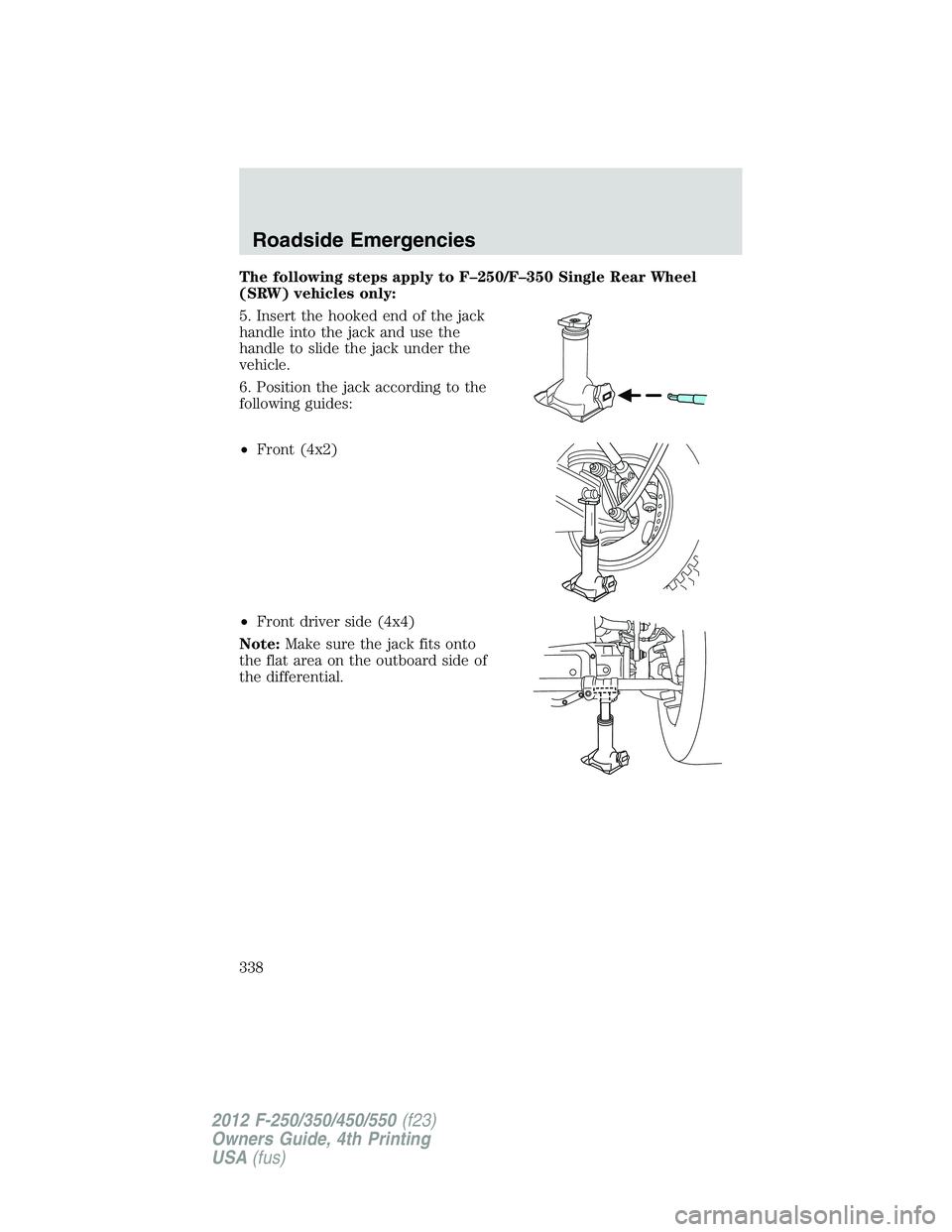
5. Insert the hooked end of the jack
handle into the jack and use the
handle to slide the jack under the
vehicle.
6. Position the jack according to the
following guides:
• Front (4x2)
• Front driver side (4x4)
Note: Make sure the jack fits onto
the flat area on the outboard side of
the differential.Roadside Emergencies
338
2012 F-250/350/450/550 (f23)
Owners Guide, 4th Printing
USA (fus)
Page 339 of 448
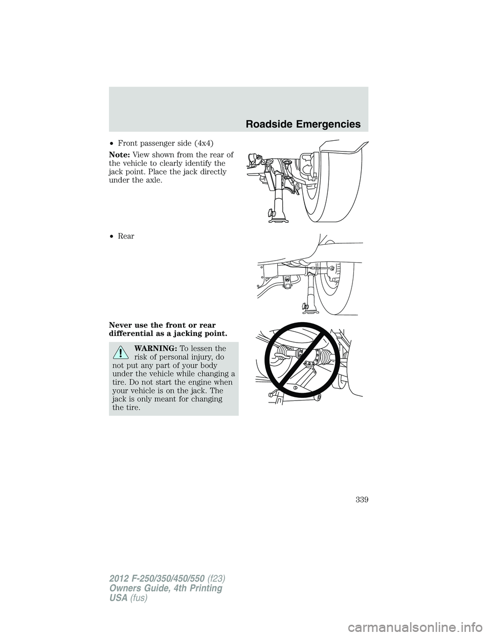
• Front passenger side (4x4)
Note: View shown from the rear of
the vehicle to clearly identify the
jack point. Place the jack directly
under the axle.
• Rear
Never use the front or rear
differential as a jacking point.
WARNING: To lessen the
risk of personal injury, do
not put any part of your body
under the vehicle while changing a
tire. Do not start the engine when
your vehicle is on the jack. The
jack is only meant for changing
the tire. Roadside Emergencies
339
2012 F-250/350/450/550 (f23)
Owners Guide, 4th Printing
USA (fus)
Page 340 of 448
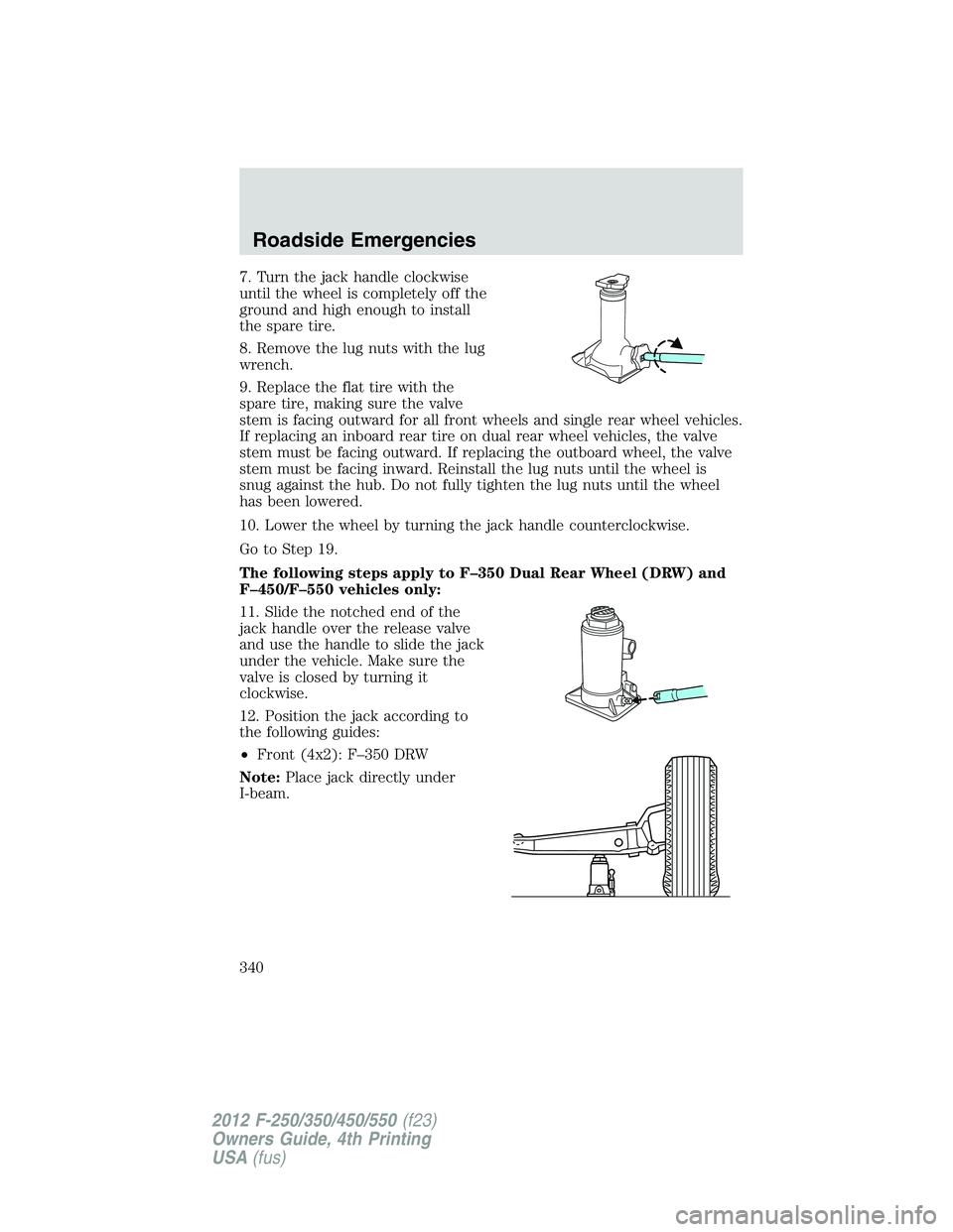
7. Turn the jack handle clockwise
until the wheel is completely off the
ground and high enough to install
the spare tire.
8. Remove the lug nuts with the lug
wrench.
9. Replace the flat tire with the
spare tire, making sure the valve
stem is facing outward for all front wheels and single rear wheel vehicles.
If replacing an inboard rear tire on dual rear wheel vehicles, the valve
stem must be facing outward. If replacing the outboard wheel, the valve
stem must be facing inward. Reinstall the lug nuts until the wheel is
snug against the hub. Do not fully tighten the lug nuts until the wheel
has been lowered.
10. Lower the wheel by turning the jack handle counterclockwise.
Go to Step 19.
The following steps apply to F–350 Dual Rear Wheel (DRW) and
F–450/F–550 vehicles only:
11. Slide the notched end of the
jack handle over the release valve
and use the handle to slide the jack
under the vehicle. Make sure the
valve is closed by turning it
clockwise.
12. Position the jack according to
the following guides:
• Front (4x2): F–350 DRW
Note: Place jack directly under
I-beam.Roadside Emergencies
340
2012 F-250/350/450/550 (f23)
Owners Guide, 4th Printing
USA (fus)