oil level FORD F650 2000 10.G Owners Manual
[x] Cancel search | Manufacturer: FORD, Model Year: 2000, Model line: F650, Model: FORD F650 2000 10.GPages: 208, PDF Size: 1.08 MB
Page 5 of 208
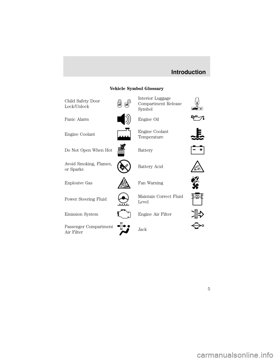
Vehicle Symbol Glossary
Child Safety Door
Lock/Unlock
Interior Luggage
Compartment Release
Symbol
Panic AlarmEngine Oil
Engine CoolantEngine Coolant
Temperature
Do Not Open When HotBattery
Avoid Smoking, Flames,
or SparksBattery Acid
Explosive GasFan Warning
Power Steering FluidMaintain Correct Fluid
LevelMAX
MIN
Emission SystemEngine Air Filter
Passenger Compartment
Air FilterJack
Introduction
5
Page 11 of 208

Parking brake warning (if equipped)
Momentarily illuminates when the
ignition is turned to the ON position
and the engine is off.
If the warning lamp remains
illuminated after engine start up,
this indicates a system failure in the master cylinder of the brake system.
Stop the vehicle safely as soon as possible and seek service immediately.
If equipped with an air brake system, the warning light stays on until the
air pressure builds up to 414 kPa (60 psi). If the air pressure drops
below 414 kPa (60 psi) durning operation, the remaining brake system is
still operational but the stopping distance will be greater.
Parking brake warning
Momentarily illuminates when the
ignition is turned to the ON position
and the engine is off. If the brake
warning lamp does not illuminate at
this time, seek service immediately.
Also illuminates when the parking
brake is engaged.
Engine protect warning (Cummins engine only)
Illuminates when there is a fault in
the electronic subsystem but the
vehicle can be driven, and indicates
one of the following conditions:
•low oil pressure
•low coolant level
•high coolant temperature
•high intake manifold temperature
Refer to the Engine Operator’s Manual.
!
BRAKE
P
BRAKE
ENGINE
PROTECT
Instrumentation
11
Page 19 of 208
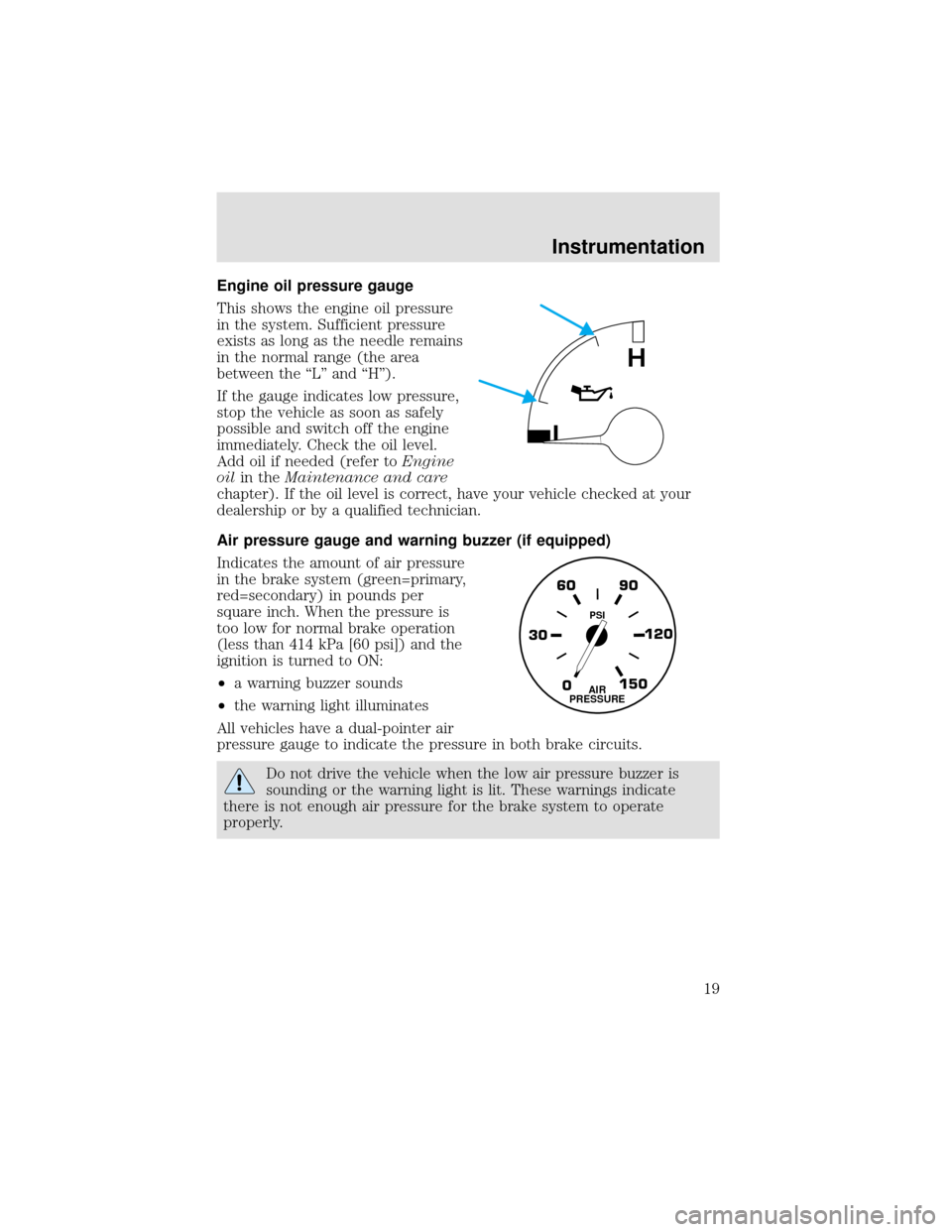
Engine oil pressure gauge
This shows the engine oil pressure
in the system. Sufficient pressure
exists as long as the needle remains
in the normal range (the area
between the“L”and“H”).
If the gauge indicates low pressure,
stop the vehicle as soon as safely
possible and switch off the engine
immediately. Check the oil level.
Add oil if needed (refer toEngine
oilin theMaintenance and care
chapter). If the oil level is correct, have your vehicle checked at your
dealership or by a qualified technician.
Air pressure gauge and warning buzzer (if equipped)
Indicates the amount of air pressure
in the brake system (green=primary,
red=secondary) in pounds per
square inch. When the pressure is
too low for normal brake operation
(less than 414 kPa [60 psi]) and the
ignition is turned to ON:
•a warning buzzer sounds
•the warning light illuminates
All vehicles have a dual-pointer air
pressure gauge to indicate the pressure in both brake circuits.
Do not drive the vehicle when the low air pressure buzzer is
sounding or the warning light is lit. These warnings indicate
there is not enough air pressure for the brake system to operate
properly.
L
H
0 30120 90 60
150AIR
PRESSURE
PSI
Instrumentation
19
Page 79 of 208
RESTARTING AFTER RUNNING OUT OF FUEL
The fuel system may need to be purged of air, refer toRunning out of
fuelin theMaintenance and carechapter.
OPERATING THE ENGINE
Do not operate the engine at full throttle below peak torque engine
speed (RPM) for more than one minute at a time (peak torque RPM
varies from 1200-1500 RPM depending on engine rated speed).
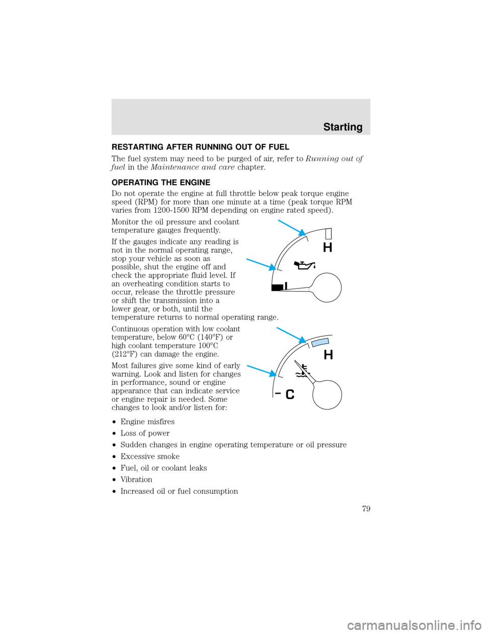
Monitor the oil pressure and coolant
temperature gauges frequently.
If the gauges indicate any reading is
not in the normal operating range,
stop your vehicle as soon as
possible, shut the engine off and
check the appropriate fluid level. If
an overheating condition starts to
occur, release the throttle pressure
or shift the transmission into a
lower gear, or both, until the
temperature returns to normal operating range.
Continuous operation with low coolant
temperature, below 60°C (140°F) or
high coolant temperature 100°C
(212°F) can damage the engine.
Most failures give some kind of early
warning. Look and listen for changes
in performance, sound or engine
appearance that can indicate service
or engine repair is needed. Some
changes to look and/or listen for:
•Engine misfires
•Loss of power
•Sudden changes in engine operating temperature or oil pressure
•Excessive smoke
•Fuel, oil or coolant leaks
•Vibration
•Increased oil or fuel consumption
L
H
H
C
Starting
79
Page 80 of 208
Excessive full throttle operation below peak torque RPM will shorten
engine life to overhaul and can cause serious engine damage. Operation
of the engine below peak torque RPM can occur during gear shifting due
to difference of gear ratios.
COLD WEATHER STARTING
Perform the following to assure efficient starting in cold weather:
•Use the proper grade oil for your climate. Refer to your engine
operator’s manual for proper grade oil.
•Test the battery more frequently to assure ample power for starting.
•All electrical connections should be tight and in good condition to
prevent losses through loose or corroded connections.
USING THE ENGINE BLOCK HEATER (IF EQUIPPED)
An engine block heater warms the engine coolant, which improves
starting, warms up the engine faster and allows the heater-defroster
system to respond quickly. Use of an engine block heater is strongly
recommended if you live in a region where temperatures reach -23°C
(-10°F) or below.
For best results, plug the heater in at least three hours before starting the
vehicle. Using the heater for longer than three hours will not harm the
engine, so the heater can be plugged in the night before starting the vehicle.
To prevent electrical shock, do not use your heater with
ungrounded electrical systems or two-pronged (cheater)
adapters.
ENGINE SHUTDOWN SYSTEM (IF EQUIPPED)
This system is designed to help prevent engine damage that could result
from operating the engine during a prolonged period of low engine oil
pressure, high engine coolant temperature or low coolant level. If any of
these conditions occur, a warning light will illuminate and a chime will
sound warning the operator that the engine will shutdown in 30 seconds.
This is to allow time for the operator to move the vehicle off the road. If
additional time is required, the engine can be restarted and run each
time for approximately 30 seconds.
Do not attempt to use this restarting feature to drive the vehicle, serious
engine damage could result.
Starting
80
Page 97 of 208
•Lack of lubricant in the front spindle bearings or linkage components
•Low oil level in the power steering system
•Broken or loose power steering pump direct drive connection
•Malfunctioning relief valve in power steering gear or steering pump
•Malfunctioning power steering pump
•Restriction in power steering lines
•Improperly set turn stops
•Air entrapped in power steering system fluid
DRIVING WITH A MANUAL TRANSMISSION, IF EQUIPPED
Continued use of a damaged or worn clutch, prolonged clutch
slippage or downshifting at excessive speeds can result in a
failure of the engine, transmission or clutch components.
To avoid premature clutch wear and failure, do not drive with
your foot resting on the clutch pedal or use it to hold the vehicle
at a standstill on an upgrade as when waiting for a traffic light.
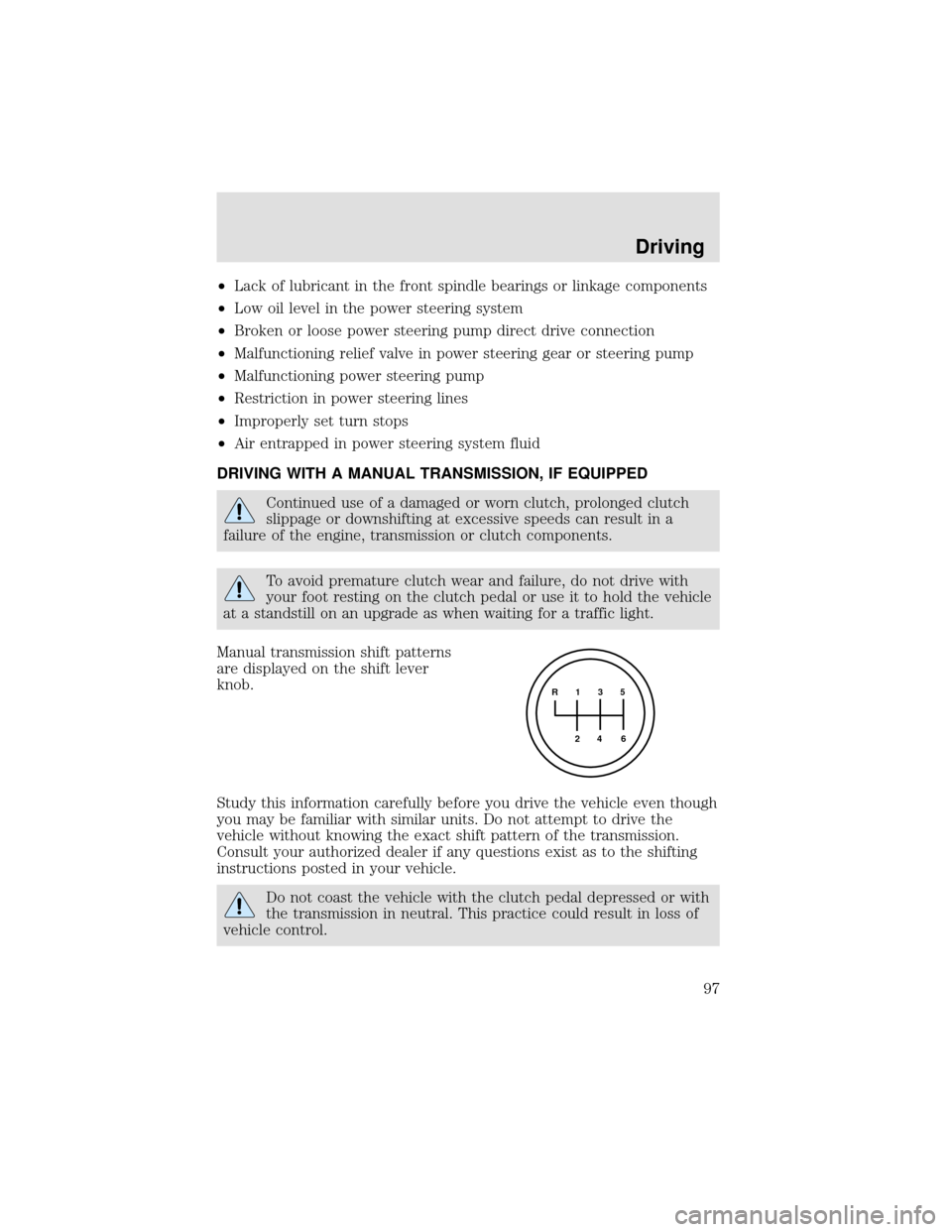
Manual transmission shift patterns
are displayed on the shift lever
knob.
Study this information carefully before you drive the vehicle even though
you may be familiar with similar units. Do not attempt to drive the
vehicle without knowing the exact shift pattern of the transmission.
Consult your authorized dealer if any questions exist as to the shifting
instructions posted in your vehicle.
Do not coast the vehicle with the clutch pedal depressed or with
the transmission in neutral. This practice could result in loss of
vehicle control.
R 1 3 5
4
6 2
Driving
97
Page 127 of 208
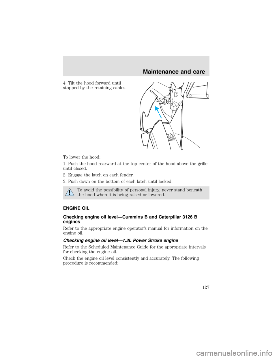
4. Tilt the hood forward until
stopped by the retaining cables.
To lower the hood:
1. Push the hood rearward at the top center of the hood above the grille
until closed.
2. Engage the latch on each fender.
3. Push down on the bottom of each latch until locked.
To avoid the possibility of personal injury, never stand beneath
the hood when it is being raised or lowered.
ENGINE OIL
Checking engine oil level—Cummins B and Caterpillar 3126 B
engines
Refer to the appropriate engine operator’s manual for information on the
engine oil.
Checking engine oil level—7.3L Power Stroke engine
Refer to the Scheduled Maintenance Guide for the appropriate intervals
for checking the engine oil.
Check the engine oil level consistently and accurately. The following
procedure is recommended:
Maintenance and care
127
Page 128 of 208

1. Start the engine and let it run until it reaches normal operating
temperature (the engine coolant temperature gauge indicator will be
near the center of the normal area between H and C).
2. Park the vehicle on level ground.
3. Set the parking brake and shift into N (Neutral) (automatic
transmission) or 1 (First) (manual transmission).
4. Turn off the engine and wait a few minutes for the oil to drain
completely into the oil pan.
5. Open the hood. Protect yourself from engine heat.
6. Locate and carefully remove the
engine oil level indicator (dipstick).
7. Wipe the indicator clean. Insert the indicator fully, then remove it
again.
•If the oil level isbetween FULL and OPERATING RANGE,the oil
level is acceptable.DO NOT ADD OIL.
•Maintain the oil level between ADD and OPERATING RANGE on the
dipstick by adding oil as required.
•The distance from ADD to OPERATING RANGE on the dipstick
represents 1.9L (2 quarts).
•Oil levels above OPERATING RANGE may cause engine damage. Some
oil must be removed from the engine by a qualified service technician.
8. Put the indicator back into the engine and ensure it is fully seated.
Maintenance and care
128
Page 135 of 208

Adding and replacing engine coolant-7.3L Power Stroke and
Cummins B engines
Refer to the Scheduled Maintenance Guide for service intervals of the
engine cooling system.
Use Ford Premium Engine Coolant E2FZ-19549–AA (in Canada,
Motorcraft CXC-8–B) or a premium engine coolant that meets Ford
specification ESE-M97B44–A. Do not use alcohol or methanol antifreeze.
The use of an improper coolant may cause cooling system and/or engine
damage and may void the warranty of your vehicle’s engine cooling
system.
A mixture of 50% engine coolant concentrate and 50% water (50/50
ratio) is recommended to maintain best overall cooling system
performance. A 60/40 antifreeze to water ratio is acceptable for
extremely cold climates, but the coolant and water mixture must be
returned to a 50/50 ratio at the end of the winter season. To avoid
damaging the cooling system and engine, the coolant and water mixture
should never exceed a 60/40 antifreeze to water ratio.
Operating the engine with insufficient coolant can cause severe
cooling system and engine damage.
When refilling the engine cooling system as part of regular maintenance
or due to service, adhere to the following instructions:
1. Drain and flush the cooling system to remove dirt deposits, oil and
rust particles. Always dispose of used automotive fluids following your
community’s standards.
2. Fill the coolant reservoir with the specified coolant and water mixture
until the level stabilizes within the cold fill range.
3. Reinstall the coolant reservoir cap.
4. Start and idle the engine until the upper radiator hose is warm
(approximately 10–15 minutes). If the hose does not get warm, repeat
this step at a higher engine speed.
5. Once the hose is warm, shut the engine off.
6. Cautiously remove the coolant reservoir cap as previously described,
and add the specified coolant and water mixture until the level stabilizes
within the cold fill range of the coolant reservoir.
7. Reinstall the engine coolant reservoir cap.
Maintenance and care
135
Page 147 of 208
SERVICING YOUR WHEELS AND TIRES
Wheel assembly
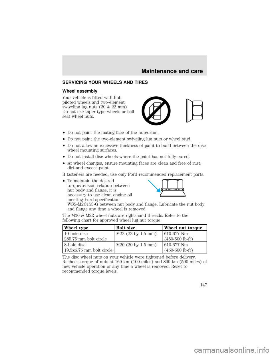
Your vehicle is fitted with hub
piloted wheels and two-element
swiveling lug nuts (20 & 22 mm).
Do not use taper type wheels or ball
seat wheel nuts.
•Do not paint the mating face of the hub/drum.
•Do not paint the two-element swiveling lug nuts or wheel stud.
•Do not allow an excessive thickness of paint to build between the disc
wheel mounting surfaces.
•Do not install disc wheels where the paint has not fully cured.
•At wheel changes, ensure mounting faces are clean and free of rust,
dirt and excess paint.
If fasteners are needed, use only Ford recommended replacement parts.
•To maintain the desired
torque/tension relation between
nut body and flange, it is
necessary to use clean engine oil
meeting Ford specification
WSS-M2C153-G between nut body and flange. Lubricate the nut body
and flange any time a wheel is removed.
The M20 & M22 wheel nuts are right-hand threads. Refer to the
following chart for approved wheel lug nut torque.
Wheel type Bolt size Wheel nut torque
10-hole disc
285.75 mm bolt circleM22 (22 by 1.5 mm) 610-677 Nm
(450-500 lb-ft)
8-hole disc
19.5x6.75 mm bolt circleM20 (20 by 1.5 mm) 610-677 Nm
(450-500 lb-ft)
The disc wheel nuts on your vehicle were tightened before delivery.
Recheck torque of nuts at 160 km (100 miles) and 800 km (500 miles) of
new vehicle operation or any time a wheel is removed. Reset to
recommended torque levels.
Maintenance and care
147