FORD F650 2004 11.G Owners Manual
Manufacturer: FORD, Model Year: 2004, Model line: F650, Model: FORD F650 2004 11.GPages: 264, PDF Size: 1.47 MB
Page 101 of 264
Unexpected and possible sudden vehicle movement may occur if
these precautions are not taken.
If the service brakes should fail to operate while the vehicle is in motion,
you can make an emergency stop with the parking brake. The stopping
distance, however, will be much greater than normal. Repairs should be
made immediately to an inoperative air brake system circuit.
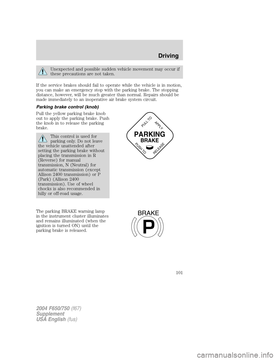
Parking brake control (knob)
Pull the yellow parking brake knob
out to apply the parking brake. Push
the knob in to release the parking
brake.
This control is used for
parking only. Do not leave
the vehicle unattended after
setting the parking brake without
placing the transmission in R
(Reverse) for manual
transmission, N (Neutral) for
automatic transmission (except
Allison 2400 transmission) or P
(Park) (Allison 2400
transmission). Use of wheel
chocks is also recommended in
hilly or off-road usage.
The parking BRAKE warning lamp
in the instrument cluster illuminates
and remains illuminated (when the
ignition is turned ON) until the
parking brake is released.PARKING
BRAKE
PULL TO
RELEASE
APPLY
PUSH TO
P
BRAKE
2004 F650/750(f67)
Supplement
USA English(fus)
Driving
101
Page 102 of 264
Releasing spring brake with air pressure
The air system in all vehicles with spring-actuated rear wheel parking
brakes is equipped with a tank valve located on the supply or service air
tank for connection to an outside air supply. The valve permits the
system to be recharged with air from an outside source, releasing the
spring-actuated parking brakes. The vehicle may then be towed in an
emergency.
An outside air source can be used only if the protected system is in
operating condition. If air pressure cannot be restored in the protected
air system, the spring-actuated brakes must be released manually.
Releasing spring brake manually
Do not attempt to disassemble the parking brake chamber under
any circumstances. The high spring load may cause serious
injury if the chamber clamps are removed.
If air pressure is released from the spring brake chamber the power
spring applies the brake and, unless air pressure can be re-established,
the spring brake must be released as follows in order to move the
vehicle.
Block the wheels to prevent the vehicle from moving.
Unexpected and possibly sudden vehicle movement may occur if
these precautions are not taken.
Impact wrenches should not be used as they may damage the piston and
prevent proper caging of the spring. Do not apply more than 68 Nm (50
lb-ft) torque to the release bolt nut.
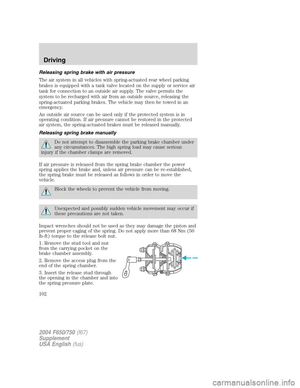
1. Remove the stud tool and nut
from the carrying pocket on the
brake chamber assembly.
2. Remove the access plug from the
end of the spring chamber.
3. Insert the release stud through
the opening in the chamber and into
the spring pressure plate.
2004 F650/750(f67)
Supplement
USA English(fus)
Driving
102
Page 103 of 264
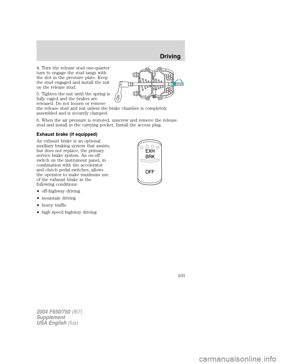
4. Turn the release stud one-quarter
turn to engage the stud tangs with
the slot in the pressure plate. Keep
the stud engaged and install the nut
on the release stud.
5. Tighten the nut until the spring is
fully caged and the brakes are
released. Do not loosen or remove
the release stud and nut unless the brake chamber is completely
assembled and is securely clamped.
6. When the air pressure is restored, unscrew and remove the release
stud and install in the carrying pocket. Install the access plug.
Exhaust brake (if equipped)
An exhaust brake is an optional
auxiliary braking system that assists,
but does not replace, the primary
service brake system. An on-off
switch on the instrument panel, in
combination with the accelerator
and clutch pedal switches, allows
the operator to make maximum use
of the exhaust brake in the
following conditions:
•off-highway driving
•mountain driving
•heavy traffic
•high speed highway driving
2004 F650/750(f67)
Supplement
USA English(fus)
Driving
103
Page 104 of 264
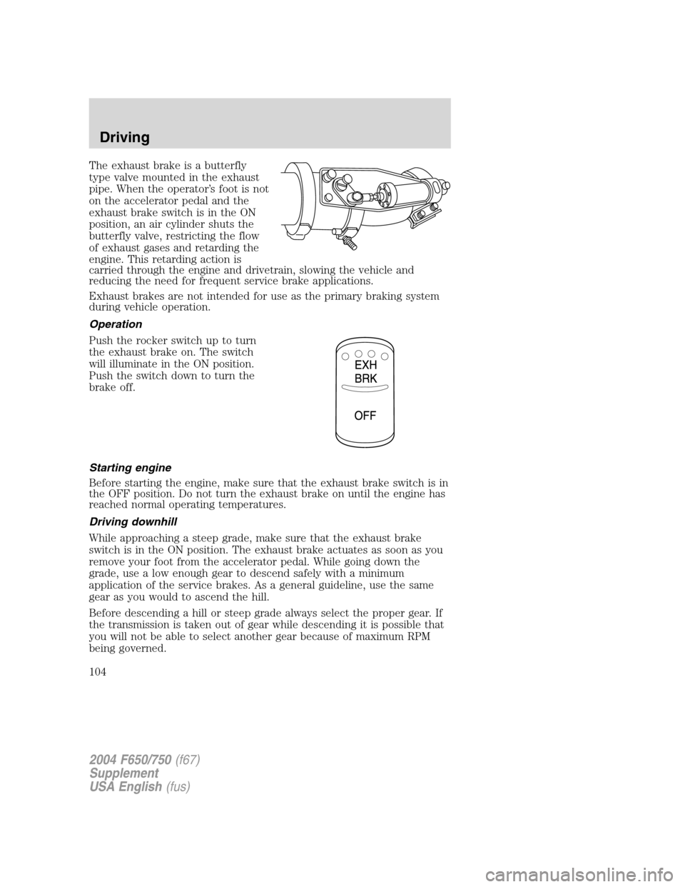
The exhaust brake is a butterfly
type valve mounted in the exhaust
pipe. When the operator’s foot is not
on the accelerator pedal and the
exhaust brake switch is in the ON
position, an air cylinder shuts the
butterfly valve, restricting the flow
of exhaust gases and retarding the
engine. This retarding action is
carried through the engine and drivetrain, slowing the vehicle and
reducing the need for frequent service brake applications.
Exhaust brakes are not intended for use as the primary braking system
during vehicle operation.
Operation
Push the rocker switch up to turn
the exhaust brake on. The switch
will illuminate in the ON position.
Push the switch down to turn the
brake off.
Starting engine
Before starting the engine, make sure that the exhaust brake switch is in
the OFF position. Do not turn the exhaust brake on until the engine has
reached normal operating temperatures.
Driving downhill
While approaching a steep grade, make sure that the exhaust brake
switch is in the ON position. The exhaust brake actuates as soon as you
remove your foot from the accelerator pedal. While going down the
grade, use a low enough gear to descend safely with a minimum
application of the service brakes. As a general guideline, use the same
gear as you would to ascend the hill.
Before descending a hill or steep grade always select the proper gear. If
the transmission is taken out of gear while descending it is possible that
you will not be able to select another gear because of maximum RPM
being governed.
2004 F650/750(f67)
Supplement
USA English(fus)
Driving
104
Page 105 of 264
Make sure the engine speed does not exceed the maximum allowable
engine RPM. Exceeding the maximum allowable engine RPM will result
in damage to the engine. Apply the service brakes to reduce the engine
RPM or make a slower descent by using a lower gear.
The exhaust brake is not recommended for use on slippery or
low traction road surfaces. Under these conditions a loss of
vehicle control could occur.
Exhaust brake operating characteristics
When you remove your feet from both the accelerator and clutch pedals
and the exhaust brake switch is in the ON position, the exhaust brake is
activated. The following conditions should exist if the brake is operating
properly:
•A slight change in the sound of the engine when the exhaust brake is
activated.
•Exhaust smoke appears normal.
•Engine temperature remains in the normal operating range.
•Road speed usually decreases when the exhaust brake is applied
during a descent, except when the vehicle is carrying a heavy load or
the grade is extremely steep. In these instances, you may need to
apply the service brakes occasionally.
•During a descent, the tachometer usually shows a drop in RPM
depending on the grade and the vehicle load.
•Do not expect a retarding effect similar to sudden hard application of
the service brakes. The exhaust brake retards the vehicle with a
smooth braking effect.
•Depending on the grade and vehicle load, you may or may not feel the
retarding force acting against your body when the brake is applied.
The brake’s retarding force is actually preventing the vehicle from
going much faster.
Make sure the exhaust brake is turned off before shutting off the engine.
Note:Installing an exhaust or auxiliary brake does not necessarily
protect the engine from exceeding maximum governed speed. The
primary brakes should be used to never allow the engine to exceed
maximum governed speed under any conditions.
2004 F650/750(f67)
Supplement
USA English(fus)
Driving
105
Page 106 of 264
Trailer brake hand control (if equipped)
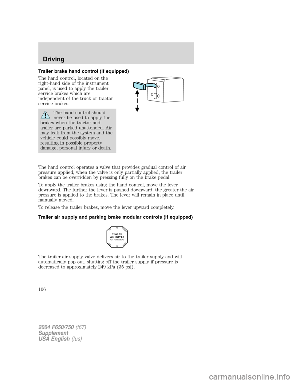
The hand control, located on the
right-hand side of the instrument
panel, is used to apply the trailer
service brakes which are
independent of the truck or tractor
service brakes.
The hand control should
never be used to apply the
brakes when the tractor and
trailer are parked unattended. Air
may leak from the system and the
vehicle could possibly move,
resulting in possible property
damage, personal injury or death.
The hand control operates a valve that provides gradual control of air
pressure applied; when the valve is only partially applied, the trailer
brakes can be overridden by pressing fully on the brake pedal.
To apply the trailer brakes using the hand control, move the lever
downward. The further the lever is pushed downward, the greater the air
pressure is applied to the brakes. The lever will remain in place until
manually moved.
To release the trailer brakes, move the lever upward completely.
Trailer air supply and parking brake modular controls (if equipped)
The trailer air supply valve delivers air to the trailer supply and will
automatically pop out, shutting off the trailer supply if pressure is
decreased to approximately 249 kPa (35 psi).
TRAILER
AIR SUPPLY
NOT FOR PARKING
TO
TOP
U
L
L
SUPPLY
EVACUATE
PUSH
2004 F650/750(f67)
Supplement
USA English(fus)
Driving
106
Page 107 of 264
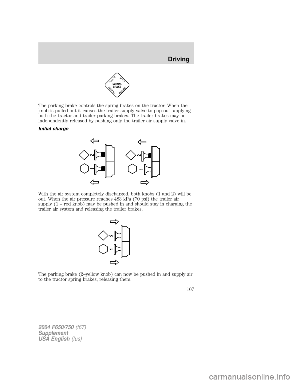
The parking brake controls the spring brakes on the tractor. When the
knob is pulled out it causes the trailer supply valve to pop out, applying
both the tractor and trailer parking brakes. The trailer brakes may be
independently released by pushing only the trailer air supply valve in.
Initial charge
With the air system completely discharged, both knobs (1 and 2) will be
out. When the air pressure reaches 483 kPa (70 psi) the trailer air
supply (1–red knob) may be pushed in and should stay in charging the
trailer air system and releasing the trailer brakes.
The parking brake (2–yellow knob) can now be pushed in and supply air
to the tractor spring brakes, releasing them.
12 12
12
2004 F650/750(f67)
Supplement
USA English(fus)
Driving
107
Page 108 of 264
Normal driving position
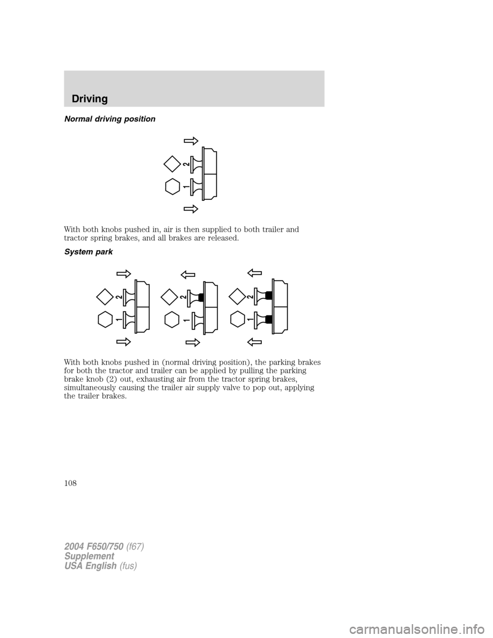
With both knobs pushed in, air is then supplied to both trailer and
tractor spring brakes, and all brakes are released.
System park
With both knobs pushed in (normal driving position), the parking brakes
for both the tractor and trailer can be applied by pulling the parking
brake knob (2) out, exhausting air from the tractor spring brakes,
simultaneously causing the trailer air supply valve to pop out, applying
the trailer brakes.
12
12
12
12
2004 F650/750(f67)
Supplement
USA English(fus)
Driving
108
Page 109 of 264
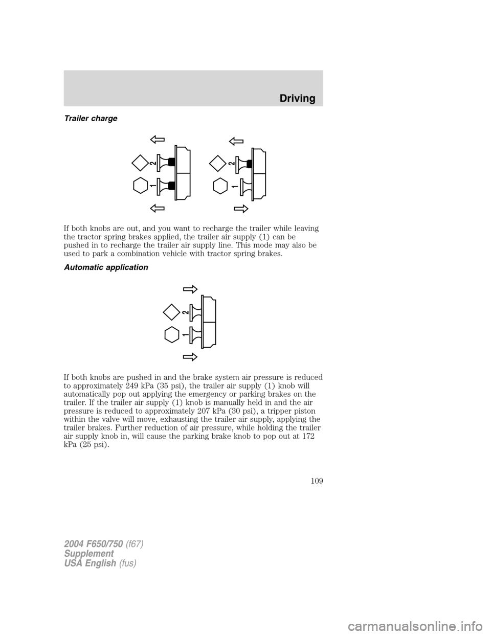
Trailer charge
If both knobs are out, and you want to recharge the trailer while leaving
the tractor spring brakes applied, the trailer air supply (1) can be
pushed in to recharge the trailer air supply line. This mode may also be
used to park a combination vehicle with tractor spring brakes.
Automatic application
If both knobs are pushed in and the brake system air pressure is reduced
to approximately 249 kPa (35 psi), the trailer air supply (1) knob will
automatically pop out applying the emergency or parking brakes on the
trailer. If the trailer air supply (1) knob is manually held in and the air
pressure is reduced to approximately 207 kPa (30 psi), a tripper piston
within the valve will move, exhausting the trailer air supply, applying the
trailer brakes. Further reduction of air pressure, while holding the trailer
air supply knob in, will cause the parking brake knob to pop out at 172
kPa (25 psi).
12 12
12
2004 F650/750(f67)
Supplement
USA English(fus)
Driving
109
Page 110 of 264
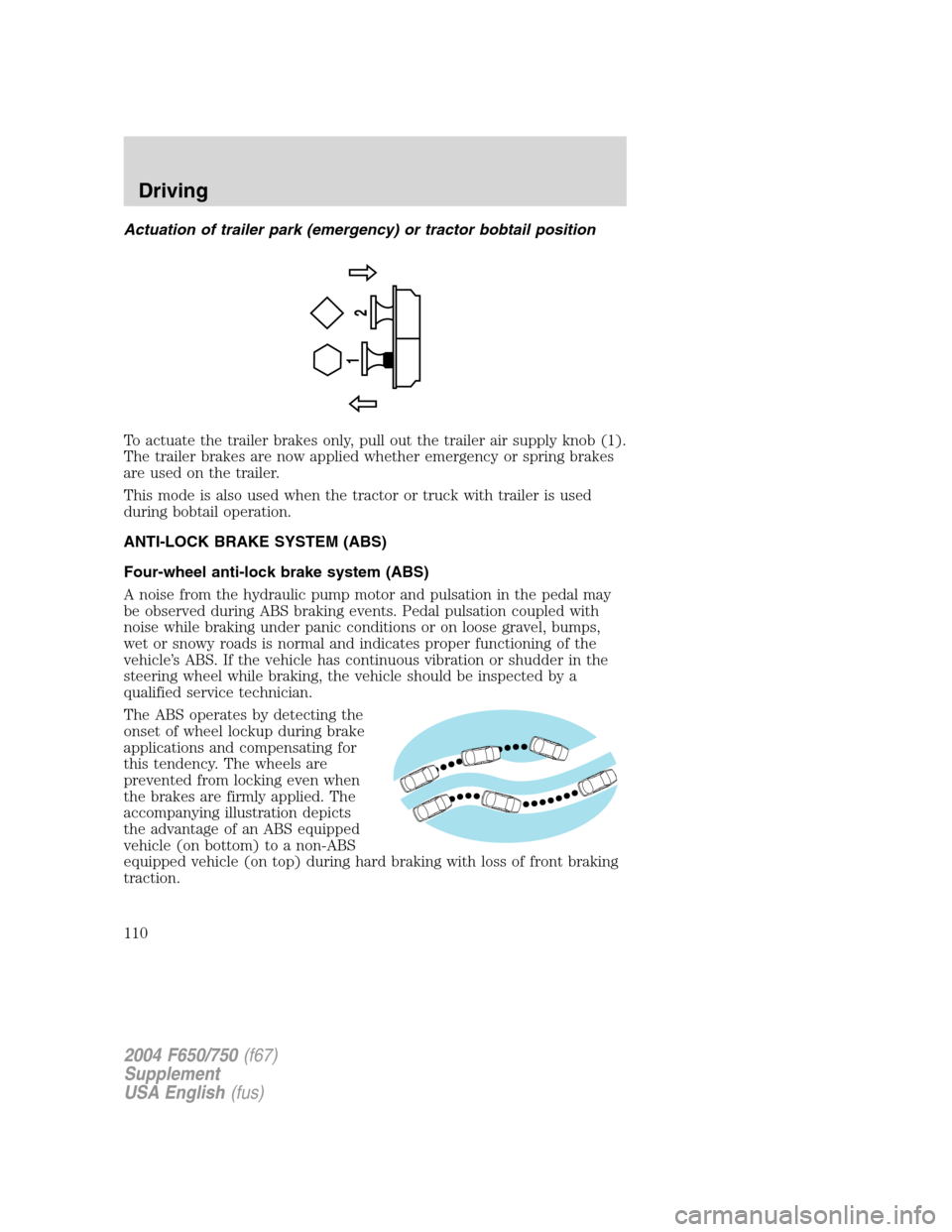
Actuation of trailer park (emergency) or tractor bobtail position
To actuate the trailer brakes only, pull out the trailer air supply knob (1).
The trailer brakes are now applied whether emergency or spring brakes
are used on the trailer.
This mode is also used when the tractor or truck with trailer is used
during bobtail operation.
ANTI-LOCK BRAKE SYSTEM (ABS)
Four-wheel anti-lock brake system (ABS)
A noise from the hydraulic pump motor and pulsation in the pedal may
be observed during ABS braking events. Pedal pulsation coupled with
noise while braking under panic conditions or on loose gravel, bumps,
wet or snowy roads is normal and indicates proper functioning of the
vehicle’s ABS. If the vehicle has continuous vibration or shudder in the
steering wheel while braking, the vehicle should be inspected by a
qualified service technician.
The ABS operates by detecting the
onset of wheel lockup during brake
applications and compensating for
this tendency. The wheels are
prevented from locking even when
the brakes are firmly applied. The
accompanying illustration depicts
the advantage of an ABS equipped
vehicle (on bottom) to a non-ABS
equipped vehicle (on top) during hard braking with loss of front braking
traction.
1
2
2004 F650/750(f67)
Supplement
USA English(fus)
Driving
110