stop start FORD F650 2004 11.G User Guide
[x] Cancel search | Manufacturer: FORD, Model Year: 2004, Model line: F650, Model: FORD F650 2004 11.GPages: 264, PDF Size: 1.47 MB
Page 116 of 264
To avoid sudden, unexpected vehicle movement and possible
personal injury or death:
1. Bring the vehicle to a complete stop.
2. Shift the transmission into: N (Neutral).
3. Apply the parking brake and make sure it is holding properly.
4. Turn the engine off when you leave the vehicle.Never leave the
vehicle unattended when the engine is running.
Allison 2400 automatic transmission with park pawl feature
Note:For Allison automatic transmission-equipped vehicles, also refer to
the separate Allison Transmission Operator’s Manual.
A parking pawl effectively grounds the transmission’s output shaft
preventing rotation of the driveline. If the vehicle is stationary, selecting
the P (Park) position places the transmission in neutral and engages the
parking pawl (always use the parking brake, also).
Note:If the P (Park) position is selected when the vehicle is in motion,
the parking pawl mechanism will ratchet andNOThold the truck.
Always set the parking brake fully. Do not use the gearshift in
place of the parking brake.
To avoid sudden, unexpected vehicle movement and possible
personal injury or death:
1. Bring the vehicle to a complete stop.
2. Shift the transmission into: P (Park). Slowly lift your foot from the
brake pedal to engage the transmission parking pawl mechanism.
3. Apply the parking brake and make sure it is holding properly. Do not
rely solely on the parking mechanism of the transmission.)
4. Turn the engine off when you leave the vehicle.Never leave the
vehicle unattended when the engine is running.
Allison MD (Medium Duty) electronic World Transmission (WT)
Two modes are available for the Allison MD-WT: Performance and
Economy. Performance mode will give you the best all-around
transmission operation; Economy provides operation at lower engine
RPM while maintaining adequate performance. The transmission will
automatically default to Performance mode when you start the engine.
Pressing MODE on the shifter will activate the Economy mode; this will
also illuminate the Mode ON lamp.
2004 F650/750(f67)
Supplement
USA English(fus)
Driving
116
Page 120 of 264
If your vehicle’s transmission is equipped with a ceramic clutch, you
must start the vehicle moving in first gear and engage the clutch before
pressing the accelerator at idle. Also, don’t try to slip the clutch by
raising engine RPM and riding or feathering the clutch pedal since the
vehicle will experience erratic engagement. Erratic engagement can
cause the engine stalling and potential serious damage to the vehicle’s
driveline components.
Clutch brake (vehicles equipped with a non-synchronized
transmission) - Vehicle stationary
A clutch brake is used to stop the transmission input shaft rotation so
that the initial 1 (First) or R (Reverse) gear selection can be
accomplished when the vehicle is stationary and the engine is running at
idle speed. Clutch brake application occurs in the last 25 mm (one inch)
of clutch pedal travel.
When using the clutch brake, fully depress the clutch pedal and shift the
transmission into 1 (First) or R (Reverse). If the transmission won’tgo
into one of these gears, slowly release the clutch pedal while applying
light pressure on the transmission shift lever until it shifts into gear.
Note:After engagement of 1 (First) gear,do notuse the clutch brake
for upshifting or downshifting. If you do, clutch brake life will shorten
and gear selection shift efforts may increase.
Double-clutch procedures - vehicles equipped with a
non-synchronized transmission
In order to properly upshift or downshift, perform the following steps:
1. Depress the clutch pedal to disengage the clutch.
2. Shift the transmission in to neutral.
3. Release the clutch pedal.
If upshifting, wait until the engine speed matches the transmission
speed of the gear you are selecting.
If downshifting,accelerate the engine until the engine speed matches
the input speed of the gear you are selecting. Depress the clutch pedal
immediately and shift into the desired gear, then release the clutch
pedal.
2004 F650/750(f67)
Supplement
USA English(fus)
Driving
120
Page 122 of 264
Shifting with a synchronized transmission
With the clutch pedal depressed, use 2 (Second) gear synchronizer to
stop the clutch disc rotation; this allows smooth engagement of 1 (First)
or R (Reverse) To complete the gear engagement, it may be necessary to
apply light pressure to the gearshift lever during initial engagement of
the clutch. It takes a second or two to match gear speeds; steady
pressure on the gearshift lever will help the synchronizer perform its job
more quickly. If the gearshift lever is forced into position, this action
defeats the purpose of the synchronizer by causing gear clash.
Shifting with a non-synchronized transmission
Refer toClutch brakeandDouble clutch proceduresin theClutch
section of this chapter.
Operating the Eaton FS-4205A and FS-5205A 5–speed
transmissions
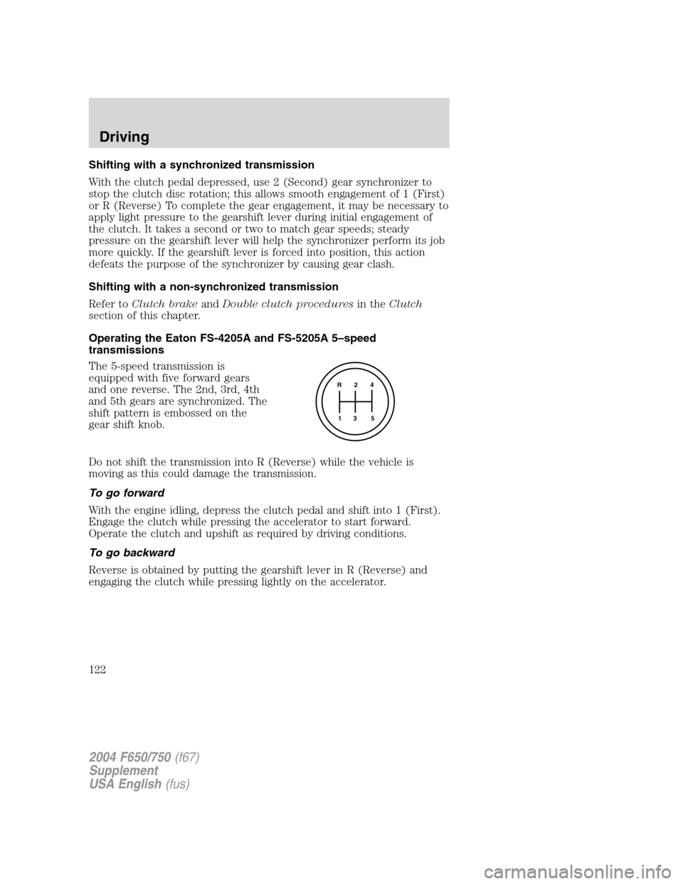
The 5-speed transmission is
equipped with five forward gears
and one reverse. The 2nd, 3rd, 4th
and 5th gears are synchronized. The
shift pattern is embossed on the
gear shift knob.
Do not shift the transmission into R (Reverse) while the vehicle is
moving as this could damage the transmission.
To go forward
With the engine idling, depress the clutch pedal and shift into 1 (First).
Engage the clutch while pressing the accelerator to start forward.
Operate the clutch and upshift as required by driving conditions.
To go backward
Reverse is obtained by putting the gearshift lever in R (Reverse) and
engaging the clutch while pressing lightly on the accelerator.
R 2 4
3 5 1
2004 F650/750(f67)
Supplement
USA English(fus)
Driving
122
Page 130 of 264
Shifting the axle from LO to HI range - vehicle moving
Accelerate to approximately 56 km/h (35 mph), press the lower part of
the switch while the transmission is in N (Neutral), then release and
apply the accelerator.
Shifting the axle from HI to LO range - vehicle stopped
Place the transmission in N (Neutral), then press the upper part of the
switch.
Note:Do not shift the axle to LO range with the vehicle in motion.
Split-shifting (combined axle and transmission shift - manual
transmissions only)
Split-shift sequence
Ratio
combination1234567891011
Transmission
gear1st 1st 2nd 2nd 3rd 3rd 4th 4th 5th 6th 6th
Axle range LO HI LO HI LO HI LO HI LO LO HI
To downshiftthe axle to a slower ratio and shift the transmission, shift
the transmission and move the control switch to the lower ratio before
the clutch is re-engaged.
To upshiftthe axle and shift the transmission, move the control switch
to a faster ratio and make the transmission shift in the usual manner.
Ratio extender use
Low End
A two-speed axle can be used as a ratio-extender when split shifting is
not necessary. For low end use, just shift the axle into the LO to start
out, and shift to HI when the extra torque is no longer needed.
Transmission
(5-speed)1st 1st 2nd 3rd 4th 5th 6th
Two-speed Axle Axle
LowAxle High
2004 F650/750(f67)
Supplement
USA English(fus)
Driving
130
Page 134 of 264
Trailer brakes
Electric brakes and manual, automatic or surge-type trailer brakes are
safe if installed properly and adjusted to the manufacturer’s
specifications. The trailer brakes must meet local and Federal
regulations.
Do not connect a trailer’s hydraulic brake system directly to your
vehicle’s brake system. Your vehicle may not have enough
braking power and your chances of having a collision greatly increase.
Trailer lamps
Trailer lamps are required on most towed vehicles. Your vehicle may be
equipped with one of two possible trailer wiring designs. Make sure all
running lights, brake lights, turn signals and hazard lights are working.
See your dealer or trailer rental agency for proper instructions and
equipment for hooking up trailer lamps.
Driving while you tow
When towing a trailer:
•Turn off the speed control. The speed control may shut off
automatically when you are towing on long, steep grades.
•Consult your local motor vehicle speed regulations for towing a trailer.
•To eliminate excessive transmission shifting, use a lower gear. This will
also assist in transmission cooling.
•Anticipate stops and brake gradually.
•Do not exceed the GCWR rating or transmission damage may occur.
Servicing after towing
If you tow a trailer for long distances, your vehicle will require more
frequent service intervals. Refer to your scheduled maintenance guide for
more information.
Trailer towing tips
•Practice turning, stopping and backing up before starting on a trip to
get the feel of the vehicle trailer combination. When turning, make
wider turns so the trailer wheels will clear curbs and other obstacles.
•Allow more distance for stopping with a trailer attached.
•The trailer tongue weight should be 10–15% of the loaded trailer
weight.
2004 F650/750(f67)
Supplement
USA English(fus)
Driving
134
Page 142 of 264
Fuse/Relay
LocationFuse Amp
RatingFuse Description
11 30A Wiper motor, Washer pump relay
12 10A Stop lamp switch (Hydraulic brake vehicles)
13 20A Cluster, Radio
14 10A Interior lamp relay
15 10A Interior lamp relay
16 15A Headlamp high beam, High beam indicator
17—Not used
18 5A Headlamp switch interior lighting
19 15A Engine control (all engines), Accelerator
pedal (6.0L Power Stroke engine)
20 15A Starting system
21 10A DRL resistor
22 15A Speed control feed (6.0L Power Stroke
engine), Air solenoid, Fuel transfer pump
23 10A Hazard flasher (Run)
24 15A ABS, Air dryer, Vacuum pump, Fuel heater
relay
25 10A Function selector switch
26 10A RH headlamp low beam
27—Not used
28 10A LH headlamp low beam
29 10A Cluster warning lamps, Gauges GEM,
Hydraulic brake ABS
30—Not used
31 15A Allison transmission or ABS event
Relay 1 1/2 ISO Interior lamp relay
Relay 2 1/2 ISO Not used
Relay 3 Full ISO Horn relay
Relay 4 Full ISO One-touch window down relay
Relay 5 Full ISO Not used
2004 F650/750(f67)
Supplement
USA English(fus)
Roadside emergencies
142
Page 166 of 264
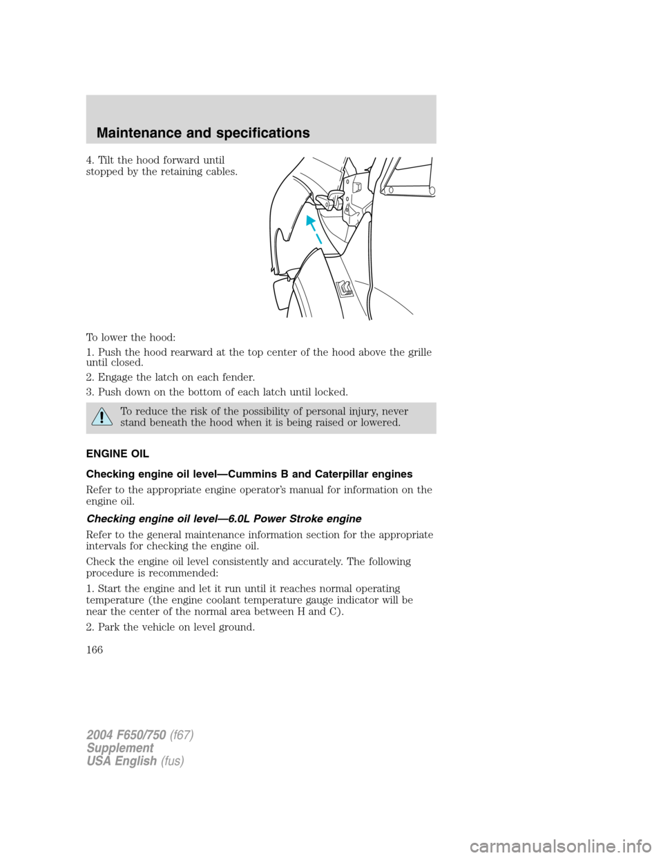
4. Tilt the hood forward until
stopped by the retaining cables.
To lower the hood:
1. Push the hood rearward at the top center of the hood above the grille
until closed.
2. Engage the latch on each fender.
3. Push down on the bottom of each latch until locked.
To reduce the risk of the possibility of personal injury, never
stand beneath the hood when it is being raised or lowered.
ENGINE OIL
Checking engine oil level—Cummins B and Caterpillar engines
Refer to the appropriate engine operator’s manual for information on the
engine oil.
Checking engine oil level—6.0L Power Stroke engine
Refer to the general maintenance information section for the appropriate
intervals for checking the engine oil.
Check the engine oil level consistently and accurately. The following
procedure is recommended:
1. Start the engine and let it run until it reaches normal operating
temperature (the engine coolant temperature gauge indicator will be
near the center of the normal area between H and C).
2. Park the vehicle on level ground.
2004 F650/750(f67)
Supplement
USA English(fus)
Maintenance and specifications
166
Page 183 of 264
For effective emissions control and low operating cost, it is important
that maintenance operations listed in this section be performed at the
specified periods or mileage intervals indicated (kilometers, miles, hours,
or months, whichever comes first).
Service intervals are based upon average operating conditions. Where
dusty, frequent start and stop or heavily laden operations are
encountered, more frequent servicing will be required.
As the vehicle (engine) owner, you are responsible for the performance
of all scheduled maintenance. The required maintenance operations may
be performed by the owner at a service establishment of the owner’s
choosing. Any replacement parts used for required maintenance services
or repairs should be genuine manufacturer service parts or equivalent in
quality and performance to genuine manufacturer service parts. Use of
inferior parts hinders operations of the engine and emissions controls
and can reduce engine life and/or jeopardize the warranty.
Receipts covering the performance of regular maintenance should be
retained in the event questions arise concerning maintenance. The
receipts should be transferred to each subsequent owner of the vehicle
(engine).
Catalytic converter
If your Diesel engine is equipped with a catalytic converter, it is
important to review the maintenance schedule to insure proper
functioning of the catalytic converter. Also, take precautions not to
damage the catalytic converter when servicing your engine or storing
your vehicle.
Note:If your vehicle is equipped with a catalytic converter/muffler,do
notblend waste oil with Diesel fuel. Operate only on low sulfur (less
than 500 parts per million sulfur) Diesel fuel with a cetane value of 45 or
higher.
Note:If your vehicle is equipped with a vertical exhaust pipe, it is very
important to have and maintain a rain cap on the exhaust pipe to
prevent water from entering the exhaust system and catalytic converter.
Any water entering the catalytic converter may damage the catalyst and
affect the function of the converter.
2004 F650/750(f67)
Supplement
USA English(fus)
Maintenance and specifications
183
Page 186 of 264
Use low sulfur (less than 0.05% by weight) fuel as required by the EPA
for emission compliance.
Do not mix diesel fuel with gasoline, gasohol or alcohol. This
could cause an explosion resulting in personal injury.
Do not use starting fluid such as ether or gasoline. Such fluids
can cause immediate explosive damage to the engine and
possible personal injury.
Running out of fuel
Avoid running out of fuel as this will allow air to enter the fuel system,
which will make restarting the vehicle difficult.
If you have run out of fuel:
•If your vehicle is equipped with dual fuel tanks,add at least
15–19 liters (4–5 gallons) of fuel to each tank before attempting to
restart the engine.
•If your vehicle is equipped with the Caterpillar engine,the fuel
system must be primed before attempting to restart the engine. Refer
to the engine operator’s manual for instructions on priming the engine.
•Use caution not to overheat and damage the starterby cranking
the engine for an excessive period of time. You may need to crank the
engine for a longer time than normal. If the engine fails to start in 30
seconds, turn the ignition to the OFF position and wait for two
minutes before cranking the engine again.
•Any remaining trapped air will self-purge from the fuel system once
the engine starts running.
•The engine may run rough and produce white smoke while air is in
the fuel system. This is normal and should stop after a short period of
time.
Fuel and lubricant additives
It should not be necessary to add any aftermarket fuel or lubricant
additives to your fuel tank if you use a properly formulated Diesel fuel
that meets the ASTM D 975 industry specification. Malfunctions
attributed to the use of such additives or failure to follow recommended
fuel or lubricant recommendations may not be covered under your
warranty.
2004 F650/750(f67)
Supplement
USA English(fus)
Maintenance and specifications
186
Page 188 of 264
Replace the fuel filter with Motorcraft Part No. F81Z-9N184–AA
(FD-4596).
1. Stop the vehicle andshut offthe engine.
The vehicle must be stopped with the engine off when draining
the HFCM. Fuel may ignite if separator is drained while the
engine is running or vehicle is moving.
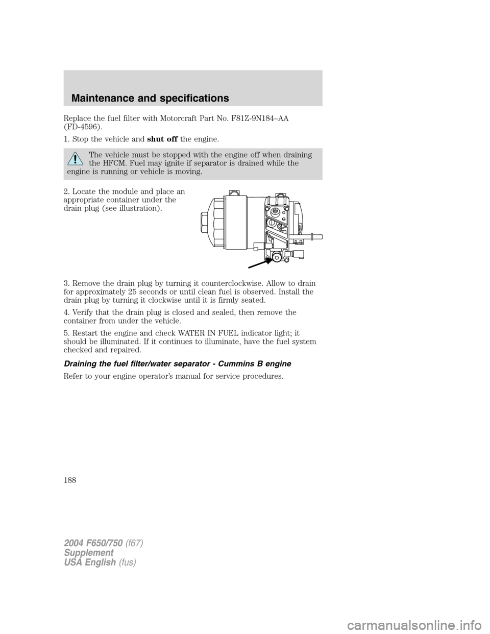
2. Locate the module and place an
appropriate container under the
drain plug (see illustration).
3. Remove the drain plug by turning it counterclockwise. Allow to drain
for approximately 25 seconds or until clean fuel is observed. Install the
drain plug by turning it clockwise until it is firmly seated.
4. Verify that the drain plug is closed and sealed, then remove the
container from under the vehicle.
5. Restart the engine and check WATER IN FUEL indicator light; it
should be illuminated. If it continues to illuminate, have the fuel system
checked and repaired.
Draining the fuel filter/water separator - Cummins B engine
Refer to your engine operator’s manual for service procedures.
2004 F650/750(f67)
Supplement
USA English(fus)
Maintenance and specifications
188