FORD F650 2006 11.G Owners Manual
Manufacturer: FORD, Model Year: 2006, Model line: F650, Model: FORD F650 2006 11.GPages: 272, PDF Size: 1.86 MB
Page 151 of 272
Fuse/Relay
LocationFuse Amp
RatingDescription
R2 — Trailer tow stop lamp relay
R3 — Trailer tow park/marker lamp relay
R4 — Trailer tow tail lamp relay
R5 — Not used
R6 — Not used
R7 — Trailer tow left turn/stop lamp relay
(combined)
Trailer tow left turn lamp relay (separate)
R8 — Trailer tow right turn/stop lamp relay
(combined)
Trailer tow right turn lamp relay (separate)
*Maxi fuse
Inline fuses
Your vehicle has two inline fuses located in/on the battery cables by the
battery. A 10A fuse for the transmission control module and a 40A fuse
for the engine control module. Refer toAutomatic transmissionin the
Drivingchapter andBatteryin theMaintenance and Specifications
chapter for more information.
JUMP STARTING
The gases around the battery can explode if exposed to flames,
sparks, or lit cigarettes. An explosion could result in injury or
vehicle damage.
Batteries contain sulfuric acid which can burn skin, eyes and
clothing, if contacted.
Do not attempt to push-start your vehicle. Automatic
transmissions do not have push-start capability; doing so may
damage the catalytic converter.
2006 F-650/750(f67)
Supplement
USA(fus)
Roadside Emergencies
151
Page 152 of 272
Before connecting a fast-charger, booster battery or installing a new
battery, make sure the ground polarities of the fast-charger, booster
battery or alternator (when installing a battery) are matched to the
ground polarity of the vehicle battery. Improper usage of the
fast-charger, hook-up of booster battery or installation of a new battery
can cause damage to the electrical system or to the alternator. Do not
attempt to polarize the alternator.
Preparing your vehicle
1.Use only a 12–volt supply to start your vehicle.Do not attach the
jumper cables to the glow plug relay as this could severely damage the
glow plugs, injector driver module and PCM.
2. Do not disconnect the battery of the disabled vehicle as this could
damage the vehicle’s electrical system.
3. Park the booster vehicle close to the hood of the disabled vehicle
making sure the two vehiclesdo nottouch. Set the parking brake on
both vehicles and stay clear of the engine cooling fan and other moving
parts.
4. Check all battery terminals and remove any excessive corrosion before
you attach the battery cables. Ensure that vent caps are tight and level.
5. Turn the heater fan on in both vehicles to protect any electrical
surges. Turn all other accessories off.
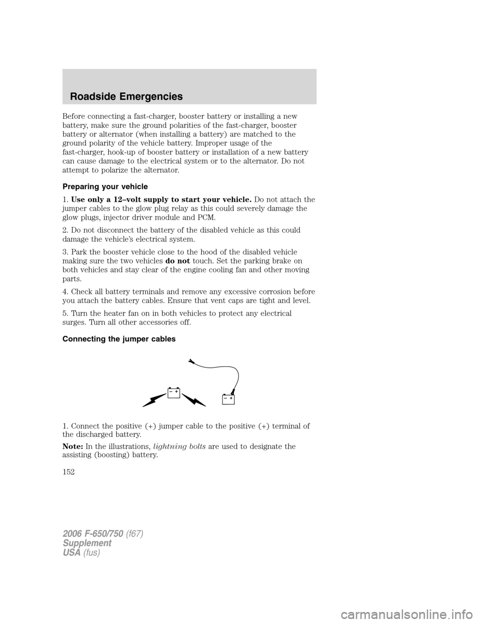
Connecting the jumper cables
1. Connect the positive (+) jumper cable to the positive (+) terminal of
the discharged battery.
Note:In the illustrations,lightning boltsare used to designate the
assisting (boosting) battery.
+–+–
2006 F-650/750(f67)
Supplement
USA(fus)
Roadside Emergencies
152
Page 153 of 272
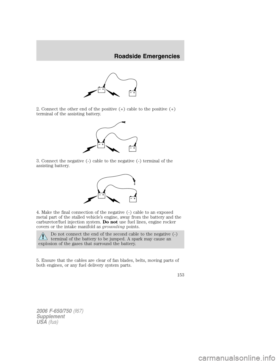
2. Connect the other end of the positive (+) cable to the positive (+)
terminal of the assisting battery.
3. Connect the negative (-) cable to the negative (-) terminal of the
assisting battery.
4. Make the final connection of the negative (-) cable to an exposed
metal part of the stalled vehicle’s engine, away from the battery and the
carburetor/fuel injection system.Do notuse fuel lines, engine rocker
covers or the intake manifold asgroundingpoints.
Do not connect the end of the second cable to the negative (-)
terminal of the battery to be jumped. A spark may cause an
explosion of the gases that surround the battery.
5. Ensure that the cables are clear of fan blades, belts, moving parts of
both engines, or any fuel delivery system parts.
+–+–
+–+–
+–+–
2006 F-650/750(f67)
Supplement
USA(fus)
Roadside Emergencies
153
Page 154 of 272
Jump starting
1. Start the engine of the booster vehicle and run the engine at
moderately increased speed.
2. Start the engine of the disabled vehicle.
3. Once the disabled vehicle has been started, run both engines for an
additional three minutes before disconnecting the jumper cables.
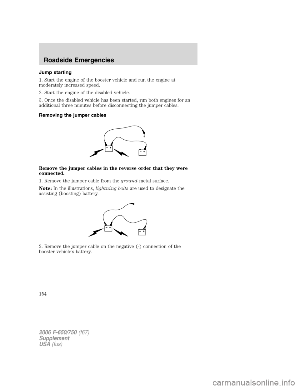
Removing the jumper cables
Remove the jumper cables in the reverse order that they were
connected.
1. Remove the jumper cable from thegroundmetal surface.
Note:In the illustrations,lightning boltsare used to designate the
assisting (boosting) battery.
2. Remove the jumper cable on the negative (-) connection of the
booster vehicle’s battery.
+–+–
+–+–
2006 F-650/750(f67)
Supplement
USA(fus)
Roadside Emergencies
154
Page 155 of 272
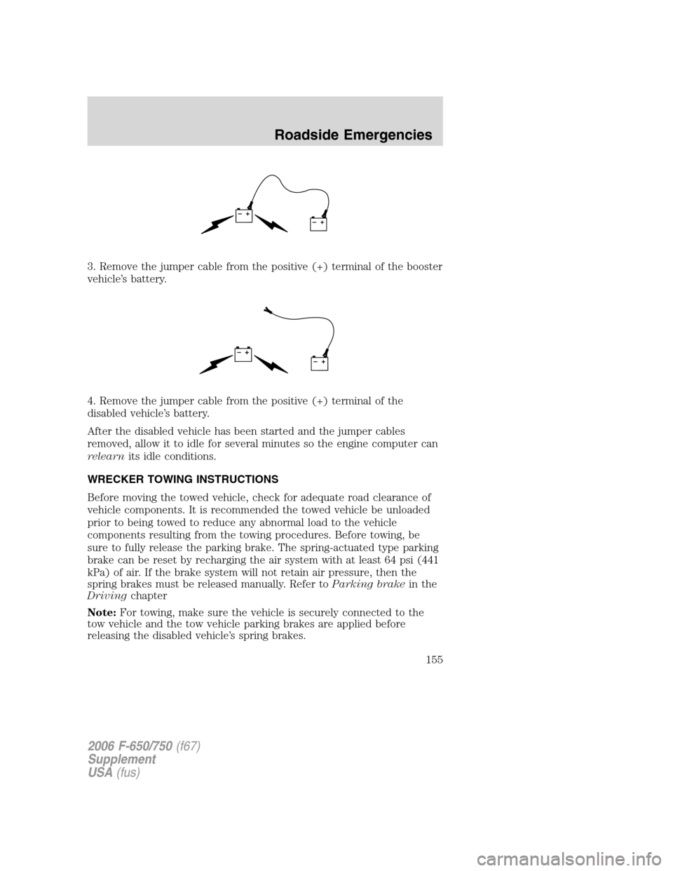
3. Remove the jumper cable from the positive (+) terminal of the booster
vehicle’s battery.
4. Remove the jumper cable from the positive (+) terminal of the
disabled vehicle’s battery.
After the disabled vehicle has been started and the jumper cables
removed, allow it to idle for several minutes so the engine computer can
relearnits idle conditions.
WRECKER TOWING INSTRUCTIONS
Before moving the towed vehicle, check for adequate road clearance of
vehicle components. It is recommended the towed vehicle be unloaded
prior to being towed to reduce any abnormal load to the vehicle
components resulting from the towing procedures. Before towing, be
sure to fully release the parking brake. The spring-actuated type parking
brake can be reset by recharging the air system with at least 64 psi (441
kPa) of air. If the brake system will not retain air pressure, then the
spring brakes must be released manually. Refer toParking brakein the
Drivingchapter
Note:For towing, make sure the vehicle is securely connected to the
tow vehicle and the tow vehicle parking brakes are applied before
releasing the disabled vehicle’s spring brakes.
+–+–
+–+–
2006 F-650/750(f67)
Supplement
USA(fus)
Roadside Emergencies
155
Page 156 of 272
To reduce the risk of personal injury or property damage when
manually releasing the spring brakes, be sure to block the wheels
so the vehicle cannot move once the brakes are released.
Towing the vehicle with the front wheels suspended
When it is necessary to tow a vehicle with the front wheels suspended,
extra precautions must be taken to avoid transmission or differential
damage. Proceed as follows:
•Remove the axle shafts from the axle assembly to prevent the wheels
from driving the differential and the transmission.
•The wheel hub ends must be covered to prevent loss of axle lubricant
and entrance of other contaminants. If the axle shafts are not
removed, removal of the propeller shaft is required.
Note:To avoid transmission damage, vehicles should not be towed even
a short distance without suspending rear wheels or removing the axle
shaft or propeller shaft.
Note:In the event the chassis is equipped with a tandem axle and the
vehicle is to be towed from the front, the forward rear axle may be
raised to clear the road surface and secured to the frame by chains or
U-bolts, allowing only the rear rear axle to contact the road surface. Axle
shafts must be removed from the rear rear axle assembly. The wheel hub
ends must be covered to prevent loss of axle lubricant and entrance of
contaminants. Use extreme care in securing the chains or U-bolts to
avoid possible damage to the brake lines, hoses or other components.
Towing vehicles equipped with a driver-controlled differential lock
Note:If the vehicle must be towed to a service facility with the drive
axle wheels on the ground, it is necessary to remove the axle shafts
before the vehicle is towed.
2006 F-650/750(f67)
Supplement
USA(fus)
Roadside Emergencies
156
Page 157 of 272
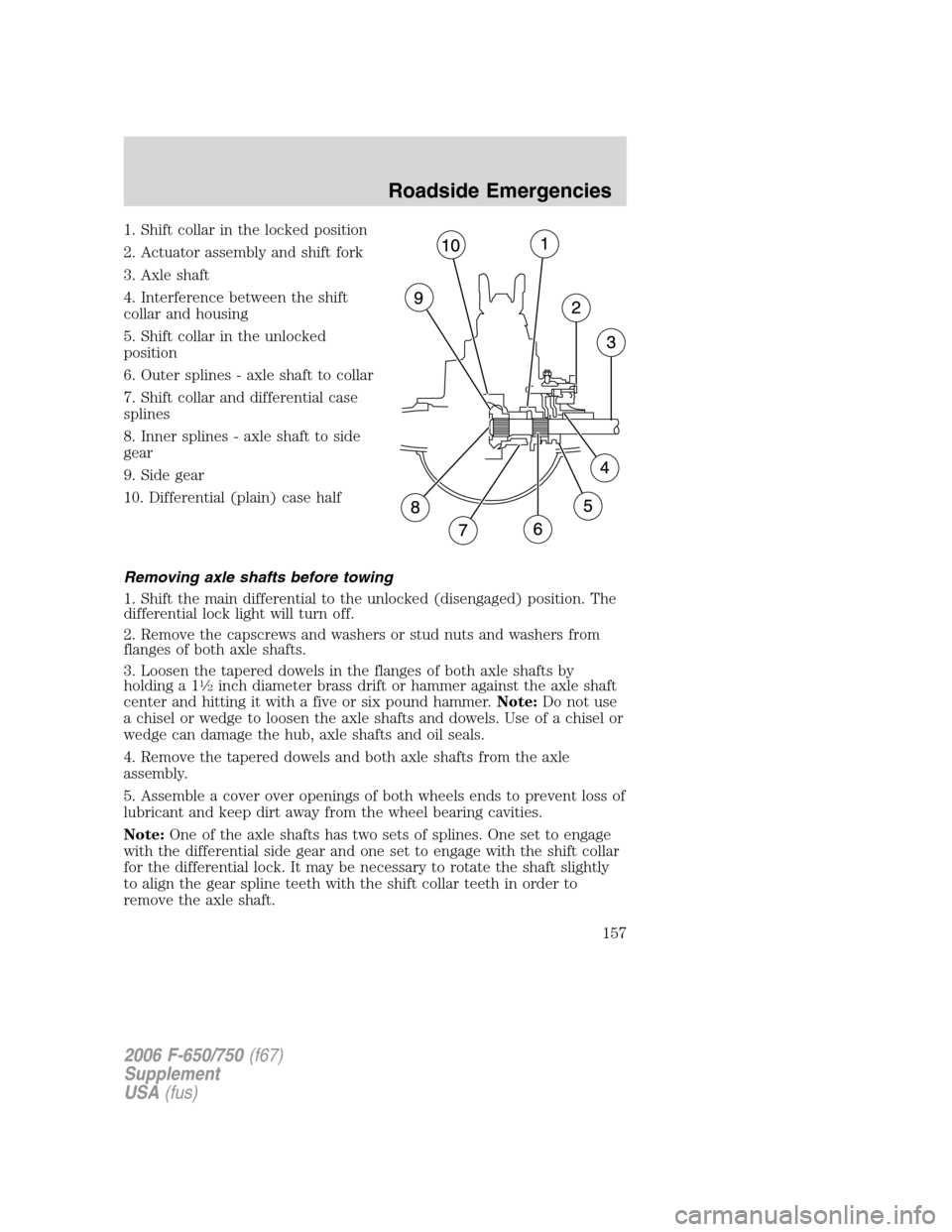
1. Shift collar in the locked position
2. Actuator assembly and shift fork
3. Axle shaft
4. Interference between the shift
collar and housing
5. Shift collar in the unlocked
position
6. Outer splines - axle shaft to collar
7. Shift collar and differential case
splines
8. Inner splines - axle shaft to side
gear
9. Side gear
10. Differential (plain) case half
Removing axle shafts before towing
1. Shift the main differential to the unlocked (disengaged) position. The
differential lock light will turn off.
2. Remove the capscrews and washers or stud nuts and washers from
flanges of both axle shafts.
3. Loosen the tapered dowels in the flanges of both axle shafts by
holding a 1
1�2inch diameter brass drift or hammer against the axle shaft
center and hitting it with a five or six pound hammer.Note:Do not use
a chisel or wedge to loosen the axle shafts and dowels. Use of a chisel or
wedge can damage the hub, axle shafts and oil seals.
4. Remove the tapered dowels and both axle shafts from the axle
assembly.
5. Assemble a cover over openings of both wheels ends to prevent loss of
lubricant and keep dirt away from the wheel bearing cavities.
Note:One of the axle shafts has two sets of splines. One set to engage
with the differential side gear and one set to engage with the shift collar
for the differential lock. It may be necessary to rotate the shaft slightly
to align the gear spline teeth with the shift collar teeth in order to
remove the axle shaft.
2006 F-650/750(f67)
Supplement
USA(fus)
Roadside Emergencies
157
Page 158 of 272
Installing the axle shafts
1. Remove the covers from the wheel ends
2. Shift the differential lock to the unlocked position (disengaged)
position.
3. Install the axle shafts
•Place the gaskets on the wheel hub studs.
•Push the right-hand axle shaft and gasket into the wheel end and
housing until the shaft stops against the differential shift collar.
•Push down and in on the axle shaft flange and rotate the shaft until
the splines of the shaft and shift collar are engaged.
•Push the axle shaft further into the housing until the shaft stops
against the differential side gear.
•Push down on the axle shaft flange and rotate the shaft until the
splines of the shaft and side gear are engaged.
•Push the axle shaft completely into the housing until the axle shaft
flange and the gasket are flush against the wheel hub.
•Install the left-hand axle shaft and gasket into the wheel end.
4. If tapered dowels are required, install them at each stud and into the
flange of the axle shaft. Use a punch or drift and hammer, if needed.
5. Install the fasteners and tighten to correct torque value. Refer to the
Service Manual section.
Towing the vehicle with the rear wheels suspended
Note:To avoid damage to the cab roof or air deflector when towing the
vehicle backward (rear wheels suspended) the air deflector must be
removed.
Whenever possible, it is preferable to tow a disabled vehicle from the
rear by raising the rear of the chassis. When towing a vehicle with the
rear of the chassis suspended the front wheels must be locked in the
straight-ahead position.
Vehicles equipped with a manual-shift transmission must have at least
1.0 pint (0.5L) of transmission fluid drained from the case. This will
prevent the transmission fluid from entering the clutch housing and fluid
saturating the clutch discs. Make sure that the transmission fluid is
replaced before the vehicle is returned to service.
2006 F-650/750(f67)
Supplement
USA(fus)
Roadside Emergencies
158
Page 159 of 272
GETTING THE SERVICES YOU NEED
At home
Ford Motor Company and Ford of Canada have authorized dealerships to
service your vehicle. It is preferred that you return to the authorized
dealer where your vehicle was purchased when warranty repairs are
needed. However, you may also take your vehicle to another Ford Motor
Company or Ford of Canada dealership authorized for warranty repairs.
Please note that certain warranty repairs require special training and/or
equipment, so not all dealers are authorized to perform all warranty
repairs. That means that depending on the warranty repair needed, the
vehicle may need to be taken to another dealer. If a particular dealership
cannot assist you, then contact the Commercial Vehicle Hotline.
If you have questions or concerns, or are unsatisfied with the service you
are receiving, follow these steps:
1. Contact your Sales Representative or Service Advisor at your
selling/servicing dealership.
2. If your inquiry or concern remains unresolved, contact the Sales
Manager or Service Manager at the dealership.
3. If the inquiry or concern cannot be resolved at the dealership level,
please contact the Ford Commercial Vehicle Hotline.
Away from home
If you own a F-650 or F-750 and need more help than the dealership can
provide after following the steps provided above call the Ford Fleet and
Commercial Vehicle Hotline.
In the United States:
Ford Motor Company
Commercial Vehicle Hotline
1655 Fairlane Circle
Allen Park, MI 48101
800-782-8627 (option #3)
(TDD for the hearing impaired: 1-800-232-5952)
www.fleet.ford.com
In Canada:
Customer Relationship Centre
Ford Motor Company of Canada, Limited
P.O. Box 2000
Oakville, Ontario L6J 5E4
1-800-565-3673 (FORD)
www.ford.ca
2006 F-650/750(f67)
Supplement
USA(fus)
Customer Assistance
159
Page 160 of 272

In order to help you service your Ford vehicle, please have the following
information available when contacting the Commercial Vehicle Hotline:
•Your telephone number (home and business)
•The name of the dealer and the city where the dealership is located
•The year and make of your vehicle
•The date of vehicle purchase
•The current odometer reading
•The vehicle identification number (VIN)
Additional assistance
If you still have a complaint involving a warranty dispute, you must
directly notify Ford in writing before pursuing remedies under your
state’s warranty laws. Ford is also allowed a final repair attempt in some
states.
IN CALIFORNIA (U.S. ONLY)
California Civil Code Section 1793.2(d) requires that, if a manufacturer
or its representative is unable to repair a motor vehicle to conform to the
vehicle’s applicable express warranty after a reasonable number of
attempts, the manufacturer shall be required to either replace the
vehicle with one substantially identical or repurchase the vehicle and
reimburse the buyer in an amount equal to the actual price paid or
payable by the consumer (less a reasonable allowance for consumer
use). The consumer has the right to choose whether to receive a refund
or replacement vehicle.
California Civil Code Section 1793.22(b) presumes that the manufacturer
has had a reasonable number of attempts to conform the vehicle to its
applicable express warranties if, within the first 18 months of ownership
of a new vehicle or the first 18,000 miles (29,000 km), whichever occurs
first:
1. Two or more repair attempts are made on the same nonconformity
likely to cause death or serious bodily injury OR
2. Four or more repair attempts are made on the same nonconformity (a
defect or condition that substantially impairs the use, value or safety of
the vehicle) OR
3. The vehicle is out of service for repair of nonconformities for a total of
more than 30 calendar days (not necessarily all at one time)
2006 F-650/750(f67)
Supplement
USA(fus)
Customer Assistance
160