light FORD F650 2010 12.G Workshop Manual
[x] Cancel search | Manufacturer: FORD, Model Year: 2010, Model line: F650, Model: FORD F650 2010 12.GPages: 274, PDF Size: 1.51 MB
Page 137 of 274
Unloaded or lightly loaded vehicles
The braking system has been designed to safely stop your vehicle when
fully loaded to its GVWR.
WARNING:When operating empty or lightly loaded, sudden or
hard braking may induce wheel lockup with loss of vehicle
control and the possibility of accident and serious injury, especially on
wet or slippery road surfaces.
TRAILER TOWING
Towing a trailer places an additional load on your vehicle’s engine,
transmission, axle, brakes, tires and suspension. Inspect these
components carefully prior to and after any towing operation.
Your vehicle’s load capacity is designated by weight, not by volume, so
you cannot necessarily use all available space when loading a vehicle.
2nd unit bodies are not included in maximum trailer weight ratings. The
weight of the additional “body” must be subtracted from the maximum
trailer weight.
Note:Do not exceed the GVWR or the GAWR specified on the
certification label.
WARNING:Towing trailers beyond the maximum recommended
gross trailer weight exceeds the limit of the vehicle and could
result in engine damage, transmission damage, structural damage, loss
of vehicle control, vehicle rollover and personal injury.
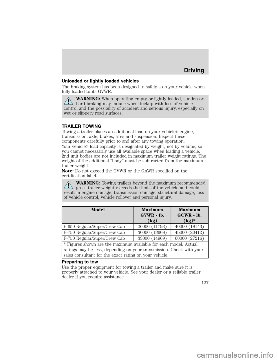
Model Maximum
GVWR - lb.
(kg)Maximum
GCWR - lb.
(kg)*
F-650 Regular/Super/Crew Cab 26000 (11793) 40000 (18143)
F-750 Regular/Super/Crew Cab 30000 (13608) 45000 (20412)
F-750 Regular/Super/Crew Cab 33000 (14969) 60000 (27216)
* Figures shown are the maximum available for each model. Actual
ratings may be less, depending on your transmission. Check with your
sales consultant for the exact rating on your vehicle.
Preparing to tow
Use the proper equipment for towing a trailer and make sure it is
properly attached to your vehicle. See your dealer or a reliable trailer
dealer if you require assistance.
Driving
137
2010 F-650/750(f67)
Supplement(supplement), 1st Printing
USA(fus)
Page 138 of 274
Hitches
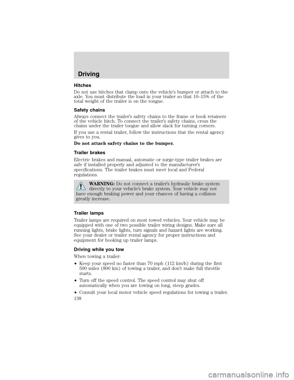
Do not use hitches that clamp onto the vehicle’s bumper or attach to the
axle. You must distribute the load in your trailer so that 10–15% of the
total weight of the trailer is on the tongue.
Safety chains
Always connect the trailer’s safety chains to the frame or hook retainers
of the vehicle hitch. To connect the trailer’s safety chains, cross the
chains under the trailer tongue and allow slack for turning corners.
If you use a rental trailer, follow the instructions that the rental agency
gives to you.
Do not attach safety chains to the bumper.
Trailer brakes
Electric brakes and manual, automatic or surge-type trailer brakes are
safe if installed properly and adjusted to the manufacturer’s
specifications. The trailer brakes must meet local and Federal
regulations.
WARNING:Do not connect a trailer’s hydraulic brake system
directly to your vehicle’s brake system. Your vehicle may not
have enough braking power and your chances of having a collision
greatly increase.
Trailer lamps
Trailer lamps are required on most towed vehicles. Your vehicle may be
equipped with one of two possible trailer wiring designs. Make sure all
running lights, brake lights, turn signals and hazard lights are working.
See your dealer or trailer rental agency for proper instructions and
equipment for hooking up trailer lamps.
Driving while you tow
When towing a trailer:
•Keep your speed no faster than 70 mph (112 km/h) during the first
500 miles (800 km) of towing a trailer, and don’t make full throttle
starts.
•Turn off the speed control. The speed control may shut off
automatically when you are towing on long, steep grades.
•Consult your local motor vehicle speed regulations for towing a trailer.
Driving
138
2010 F-650/750(f67)
Supplement(supplement), 1st Printing
USA(fus)
Page 140 of 274
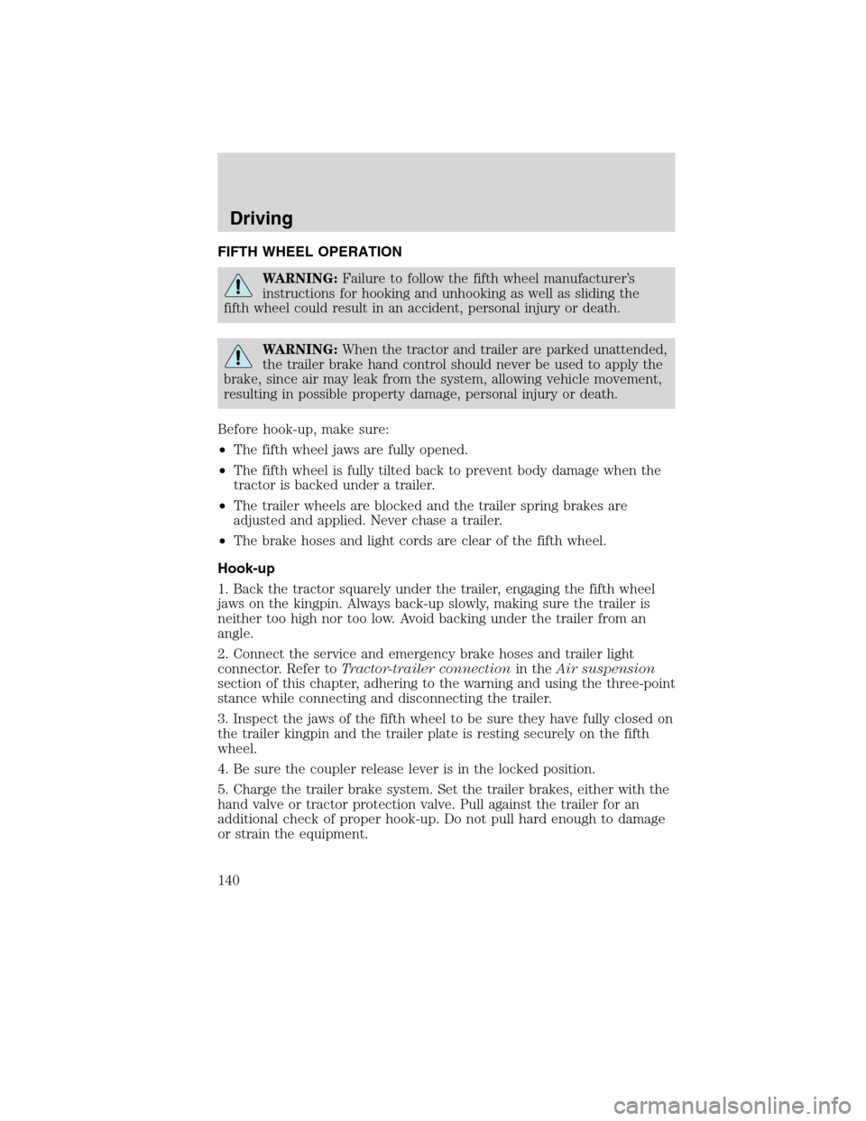
FIFTH WHEEL OPERATION
WARNING:Failure to follow the fifth wheel manufacturer’s
instructions for hooking and unhooking as well as sliding the
fifth wheel could result in an accident, personal injury or death.
WARNING:When the tractor and trailer are parked unattended,
the trailer brake hand control should never be used to apply the
brake, since air may leak from the system, allowing vehicle movement,
resulting in possible property damage, personal injury or death.
Before hook-up, make sure:
•The fifth wheel jaws are fully opened.
•The fifth wheel is fully tilted back to prevent body damage when the
tractor is backed under a trailer.
•The trailer wheels are blocked and the trailer spring brakes are
adjusted and applied. Never chase a trailer.
•The brake hoses and light cords are clear of the fifth wheel.
Hook-up
1. Back the tractor squarely under the trailer, engaging the fifth wheel
jaws on the kingpin. Always back-up slowly, making sure the trailer is
neither too high nor too low. Avoid backing under the trailer from an
angle.
2. Connect the service and emergency brake hoses and trailer light
connector. Refer toTractor-trailer connectionin theAir suspension
section of this chapter, adhering to the warning and using the three-point
stance while connecting and disconnecting the trailer.
3. Inspect the jaws of the fifth wheel to be sure they have fully closed on
the trailer kingpin and the trailer plate is resting securely on the fifth
wheel.
4. Be sure the coupler release lever is in the locked position.
5. Charge the trailer brake system. Set the trailer brakes, either with the
hand valve or tractor protection valve. Pull against the trailer for an
additional check of proper hook-up. Do not pull hard enough to damage
or strain the equipment.
Driving
140
2010 F-650/750(f67)
Supplement(supplement), 1st Printing
USA(fus)
Page 141 of 274

6. Set the tractor parking brakes and fully raise the trailer landing gear.
Refer toBrakesin this chapter for proper operation of the parking brake
and trailer brakes.
7. Check the operation of all trailer lights and correct any lights that may
be faulty.
Un-hook
1. Try to keep the tractor and trailer in a straight line.
2. Apply the parking brakes.
3. Lower the trailer landing gear, making sure it is on solid, level ground.
The weight of the trailer is to be on the landing gear.
4. Block the trailer wheels.
5. Disconnect the brake hoses and light cords. Be sure hoses and cords
are clear.
6. Pull coupler release lever to disengage the fifth wheel jaws.
7. Release the tractor parking brakes.
8. Pull out from the trailer slowly, allowing the landing gear to take the
load gradually.
Driving
141
2010 F-650/750(f67)
Supplement(supplement), 1st Printing
USA(fus)
Page 144 of 274
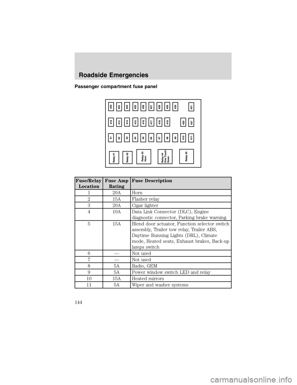
Passenger compartment fuse panel
Fuse/Relay
LocationFuse Amp
RatingFuse Description
1 20A Horn
2 15A Flasher relay
3 20A Cigar lighter
4 10A Data Link Connector (DLC), Engine
diagnostic connector, Parking brake warning
5 15A Blend door actuator, Function selector switch
assembly, Trailer tow relay, Trailer ABS,
Daytime Running Lights (DRL), Climate
mode, Heated seats, Exhaust brakes, Back-up
lamps switch
6 — Not used
7 — Not used
8 5A Radio, GEM
9 5A Power window switch LED and relay
10 15A Heated mirrors
11 5A Wiper and washer systems
Roadside Emergencies
144
2010 F-650/750(f67)
Supplement(supplement), 1st Printing
USA(fus)
Page 145 of 274
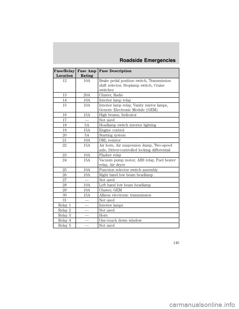
Fuse/Relay
LocationFuse Amp
RatingFuse Description
12 10A Brake pedal position switch, Transmission
shift selector, Stoplamp switch, Cruise
switches
13 20A Cluster, Radio
14 10A Interior lamp relay
15 10A Interior lamp relay, Vanity mirror lamps,
Generic Electronic Module (GEM)
16 15A High beams, Indicator
17 — Not used
18 5A Headlamp switch interior lighting
19 15A Engine control
20 5A Starting system
21 10A DRL resistor
22 15A Air horn, Air suspension dump, Two-speed
axle, Driver-controlled locking differential
23 10A Flasher relay
24 15A Vacuum pump motor, ABS relay, Fuel heater
relay, Air dryer
25 10A Function selector switch assembly
26 10A Right hand low beam headlamp
27 — Not used
28 10A Left hand low beam headlamp
29 10A Cluster, GEM
30 15A Allison electronic transmission
31 — Not used
Relay 1 — Interior lamps
Relay 2 — Not used
Relay 3 — Horn
Relay 4 — One-touch down window
Relay 5 — Not used
Roadside Emergencies
145
2010 F-650/750(f67)
Supplement(supplement), 1st Printing
USA(fus)
Page 146 of 274
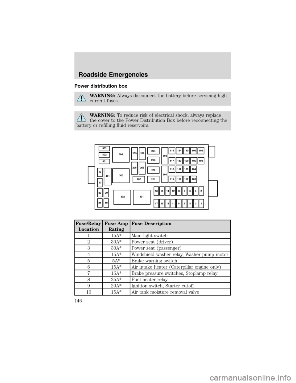
Power distribution box
WARNING:Always disconnect the battery before servicing high
current fuses.
WARNING:To reduce risk of electrical shock, always replace
the cover to the Power Distribution Box before reconnecting the
battery or refilling fluid reservoirs.
Fuse/Relay
LocationFuse Amp
RatingFuse Description
1 15A* Main light switch
2 30A* Power seat (driver)
3 30A* Power seat (passenger)
4 15A* Windshield washer relay, Washer pump motor
5 5A* Brake warning switch
6 15A* Air intake heater (Caterpillar engine only)
7 15A* Brake pressure switches, Stoplamp relay
8 25A* Fuel heater relay
9 20A* Ignition switch, Starter cutoff
10 15A* Air tank moisture removal valve
503
502
501304
303
302 301
2119 22 2024
23401
207 201202 203204
209 206
208 205602
601118114
110106
102
117 113 109105
101
116 112 108104
115 111 107103
18 16
14 12 10 864
2
17 15
13 11 9 753
1
Roadside Emergencies
146
2010 F-650/750(f67)
Supplement(supplement), 1st Printing
USA(fus)
Page 147 of 274
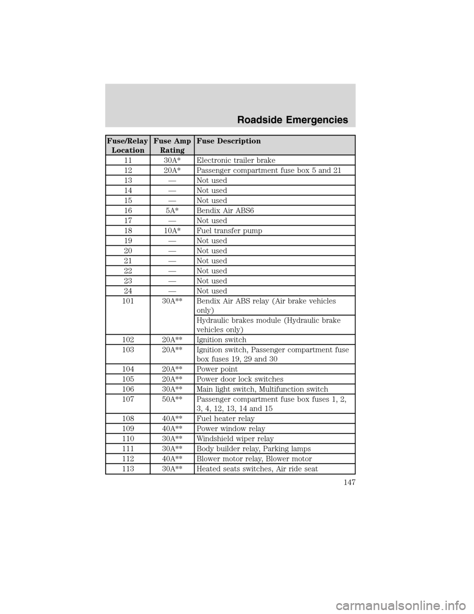
Fuse/Relay
LocationFuse Amp
RatingFuse Description
11 30A* Electronic trailer brake
12 20A* Passenger compartment fuse box 5 and 21
13 — Not used
14 — Not used
15 — Not used
16 5A* Bendix Air ABS6
17 — Not used
18 10A* Fuel transfer pump
19 — Not used
20 — Not used
21 — Not used
22 — Not used
23 — Not used
24 — Not used
101 30A** Bendix Air ABS relay (Air brake vehicles
only)
Hydraulic brakes module (Hydraulic brake
vehicles only)
102 20A** Ignition switch
103 20A** Ignition switch, Passenger compartment fuse
box fuses 19, 29 and 30
104 20A** Power point
105 20A** Power door lock switches
106 30A** Main light switch, Multifunction switch
107 50A** Passenger compartment fuse box fuses 1, 2,
3, 4, 12, 13, 14 and 15
108 40A** Fuel heater relay
109 40A** Power window relay
110 30A** Windshield wiper relay
111 30A** Body builder relay, Parking lamps
112 40A** Blower motor relay, Blower motor
113 30A** Heated seats switches, Air ride seat
Roadside Emergencies
147
2010 F-650/750(f67)
Supplement(supplement), 1st Printing
USA(fus)
Page 152 of 274
Preparing your vehicle
1.Use only a 12–volt supply to start your vehicle.Do not attach the
jumper cables to the glow plug relay as this could severely damage the
glow plugs, injector driver module and PCM.
2. Do not disconnect the battery of the disabled vehicle as this could
damage the vehicle’s electrical system.
3. Park the booster vehicle close to the hood of the disabled vehicle making
sure the two vehiclesdo nottouch. Set the parking brake on both vehicles
and stay clear of the engine cooling fan and other moving parts.
4. Check all battery terminals and remove any excessive corrosion before
you attach the battery cables. Ensure that vent caps are tight and level.
5. Turn the heater fan on in both vehicles to protect from any electrical
surges. Turn all other accessories off.
Connecting the jumper cables
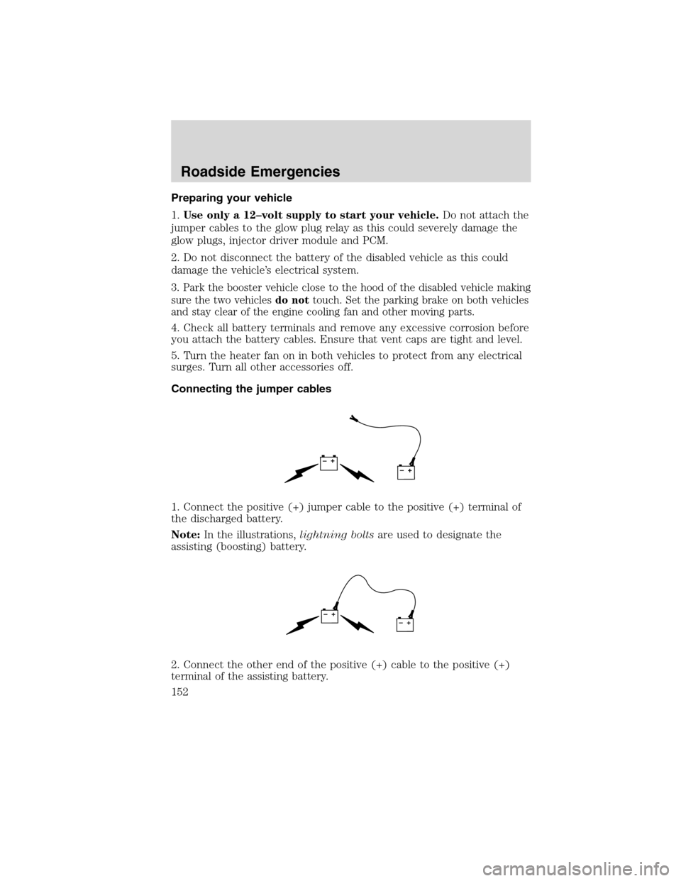
1. Connect the positive (+) jumper cable to the positive (+) terminal of
the discharged battery.
Note:In the illustrations,lightning boltsare used to designate the
assisting (boosting) battery.
2. Connect the other end of the positive (+) cable to the positive (+)
terminal of the assisting battery.
+–+–
+–+–
Roadside Emergencies
152
2010 F-650/750(f67)
Supplement(supplement), 1st Printing
USA(fus)
Page 154 of 274
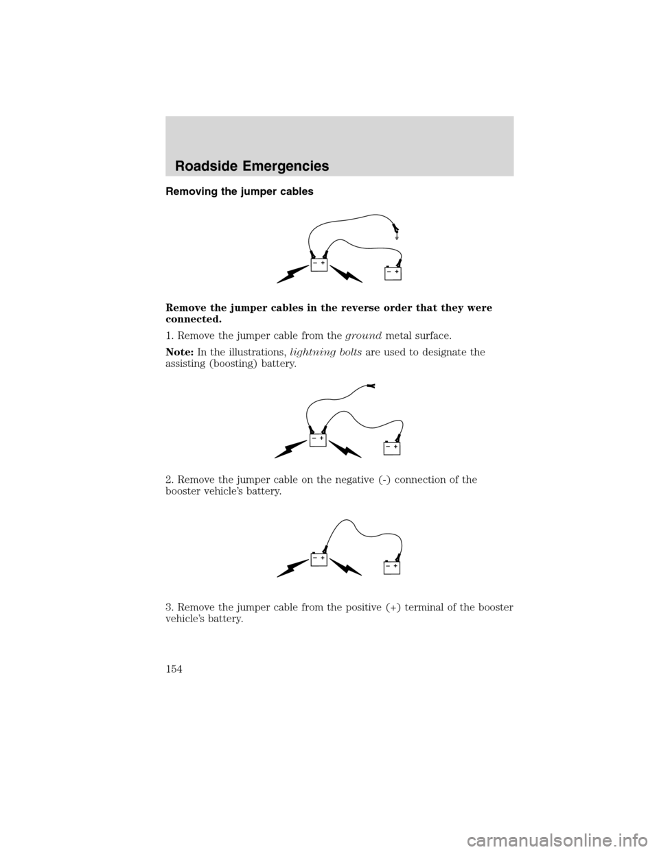
Removing the jumper cables
Remove the jumper cables in the reverse order that they were
connected.
1. Remove the jumper cable from thegroundmetal surface.
Note:In the illustrations,lightning boltsare used to designate the
assisting (boosting) battery.
2. Remove the jumper cable on the negative (-) connection of the
booster vehicle’s battery.
3. Remove the jumper cable from the positive (+) terminal of the booster
vehicle’s battery.
+–+–
+–+–
+–+–
Roadside Emergencies
154
2010 F-650/750(f67)
Supplement(supplement), 1st Printing
USA(fus)