wheel FORD F650 2016 13.G Owner's Manual
[x] Cancel search | Manufacturer: FORD, Model Year: 2016, Model line: F650, Model: FORD F650 2016 13.GPages: 379, PDF Size: 4.8 MB
Page 125 of 379
Note:
Read and understand the following
steps and perform them whenever you
prepare to drive the vehicle.
Note: The parking brake does not disengage
unless sufficient system air pressure is
available.
1. Press and hold the service brake pedal
while the engine is running.
2. Select the appropriate drive gear.
3. Push and hold the yellow dash-mounted parking brake knob until
the parking brake light turns off, then
release.
Parking Brake Light Illumination due
to Low Air Pressure
If the air pressure becomes too low at any
time during vehicle operation, the parking
brake may apply and the parking brake
light turns on.
If the parking brake applies due to low air
pressure, immediate service is required to
the parking brake system.
Parking Brake Warning System
If the parking brake light blinks and a tone
sounds when pulling the yellow control
knob out, this indicates the parking brake
is not functioning properly. Seek service for
the parking brake immediately.
With the ignition key not in the run position:
• A tone sounds if the parking brake
remains released (or in an unknown
state). The tone stops after
approximately 8 minutes or until the
parking brake is applied. Seek service
for the parking brake immediately. Diesel engines: Parking brake light
operation (the light only works when the
ignition key is in the run position):
• On:
Parking brake applied.
• Off:
Parking brake released and no
faults or malfunctions detected.
• Blink and tone:
Parking brake
released (or in an unknown state) and
faults or malfunctions detected.
Releasing Spring Manually WARNINGS
Do not attempt to disassemble the
parking brake chamber under any
circumstances. The high spring load
may cause serious injury. Block the wheels to help prevent the
vehicle from moving.
Unexpected and possibly sudden
vehicle movement may occur if these
precautions are not taken.
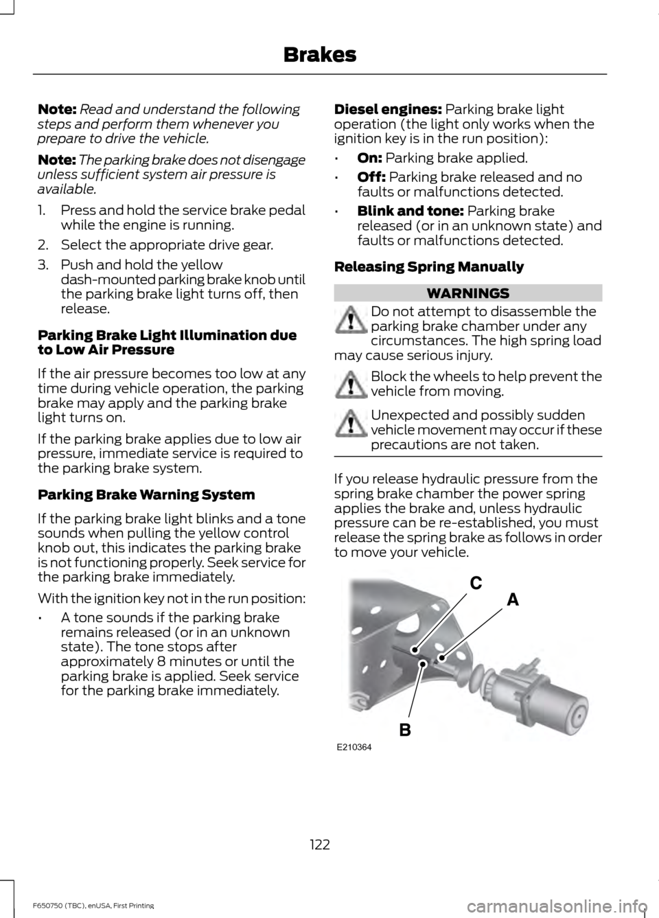
If you release hydraulic pressure from the
spring brake chamber the power spring
applies the brake and, unless hydraulic
pressure can be re-established, you must
release the spring brake as follows in order
to move your vehicle.
122
F650750 (TBC), enUSA, First Printing BrakesE210364
Page 126 of 379
Loosen the jam nut (A) and un-thread the
adjustment rod (B) from the chamber to
reduce tension on the cable (C). Continue
to un-thread the adjustment rod all the
way and remove it from the chamber.
Air Brakes
WARNING
This control is used for parking only.
Do not leave the vehicle unattended
after setting the parking brake
without placing the transmission park (P).
Use of wheel chocks is also recommended
in hilly or off-road usage. If the service brakes should fail to operate
while your vehicle is moving, you can make
an emergency stop with the parking brake.
Since the parking brake only applies
stopping power to the rear wheels, your
vehicle
’s stopping distance greatly
increases and the handling of your vehicle
is adversely affected. Make repairs
immediately to an inoperative air brake
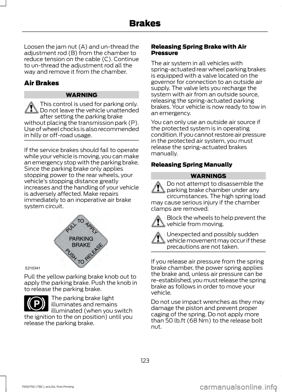
system circuit. Pull the yellow parking brake knob out to
apply the parking brake. Push the knob in
to release the parking brake.
The parking brake light
illuminates and remains
illuminated (when you switch
the ignition to the on position) until you
release the parking brake. Releasing Spring Brake with Air
Pressure
The air system in all vehicles with
spring-actuated rear wheel parking brakes
is equipped with a valve located on the
governor for connection to an outside air
supply. The valve lets you recharge the
system with air from an outside source,
releasing the spring-actuated parking
brakes. Your vehicle is now ready to tow in
an emergency.
You can only use an outside air source if
the protected system is in operating
condition. If you cannot restore air pressure
in the protected air system, you must
release the spring-actuated brakes
manually.
Releasing Spring Manually
WARNINGS
Do not attempt to disassemble the
parking brake chamber under any
circumstances. The high spring load
may cause serious injury if the chamber
clamps are removed. Block the wheels to help prevent the
vehicle from moving.
Unexpected and possibly sudden
vehicle movement may occur if these
precautions are not taken.
If you release air pressure from the spring
brake chamber, the power spring applies
the brake and, unless air pressure can be
re-established, you must release the spring
brake as follows in order to move your
vehicle.
Do not use impact wrenches as they may
damage the piston and prevent proper
caging of the spring. Do not apply more
than 50 lb.ft (68 Nm) to the release bolt
nut.
123
F650750 (TBC), enUSA, First Printing BrakesE210341 E210346
Page 135 of 379
PRINCIPLE OF OPERATION
The traction control system helps avoid
drive wheel spin and loss of traction.
If your vehicle begins to slide, the system
applies the brakes to individual wheels
and, when needed, reduces engine power
at the same time. If the wheels spin when
accelerating on slippery or loose surfaces,
the system reduces engine power in order
to increase traction.
Note:
The system does not apply the brakes
when vehicle speed is above 25 mph
(40 km/h).
USING TRACTION CONTROL -
VEHICLES WITH: AIR BRAKES WARNING
Aggressive driving in any road
conditions can cause you to lose
control of your vehicle increasing the
risk of severe personal injury or property
damage. The occurrence of a traction
control event is an indication that at least
some of the tires have exceeded their
ability to grip the road; this may lead to an
increased risk of loss of vehicle control,
vehicle rollover, personal injury and death.
If you experience a severe road event,
SLOW DOWN. Press the switch to select Off Road or
Mud/Snow traction mode. This is
beneficial when your vehicle is stuck in
snow or on a slippery road surface. This
mode allows excess wheel spin to dig your
vehicle out and allows you to rock your
vehicle.
Press the switch again to select standard
traction control. The system automatically
selects standard traction control at the
next ignition cycle. System Indicator Light
Note:
If the traction control light does not
flash during a traction control event or stays
illuminated, the system is not functioning
properly. Take your vehicle to an authorized
dealer for service.
During traction control operation, the
traction control light flashes rapidly and
the engine does not rev-up when you press
further on the accelerator. This is normal
and is no reason for concern.
In Off Road or Mud/Snow mode, the
traction control light illuminates and
flashes slowly. If a traction event occurs,
in either mode, the light flashes rapidly.
USING TRACTION CONTROL -
VEHICLES WITH: HYDRAULIC
BRAKES WARNING
Aggressive driving in any road
conditions can cause you to lose
control of your vehicle increasing the
risk of severe personal injury or property
damage. The occurrence of a traction
control event is an indication that at least
some of the tires have exceeded their
ability to grip the road; this may lead to an
increased risk of loss of vehicle control,
vehicle rollover, personal injury and death.
If you experience a severe road event,
SLOW DOWN. The system automatically turns on each
time you switch the ignition on.
Use the traction control switch on the
instrument panel to switch the system off
or on.
If your vehicle is stuck in mud or snow,
switching traction control off may be
beneficial as this allows the wheels to spin.
132
F650750 (TBC), enUSA, First Printing Traction Control
Page 137 of 379

PRINCIPLE OF OPERATION
Cruise control lets you maintain a set
speed without keeping your foot on the
accelerator pedal. You can use cruise
control when your vehicle speed is greater
than 20 mph (30 km/h).
USING CRUISE CONTROL WARNINGS
Do not use cruise control on winding
roads, in heavy traffic or when the
road surface is slippery. This could
result in loss of vehicle control, serious
injury or death. When you are going downhill, your
vehicle speed may increase above
the set speed. The system will not
apply the brakes but a warning displays.
Failure to follow this warning could result
in serious personal injury or death. Note:
Cruise control will disengage if the
vehicle speed decreases more than 10 mph
(16 km/h) below the set speed while driving
uphill. The cruise controls are on the steering
wheel.
Switching Cruise Control On
Press and release
ON.
The indicator displays in the
instrument cluster.
Setting the Cruise Speed
1. Drive to desired speed.
2. Press and release
SET+ or SET-.
3. Take your foot off the accelerator pedal.
134
F650750 (TBC), enUSA, First Printing Cruise ControlE210985 E71340
Page 139 of 379
STEERING
To help prevent damage to the power
steering system:
•
Never hold the steering wheel at its
furthest turning points (until it stops)
for more than three to five seconds
when the engine is running.
• Do not operate the vehicle with a low
power steering pump fluid level (below
the MIN mark on the reservoir).
• Some noise is normal during operation.
If excessive, check for low power
steering pump fluid level before
seeking service by your dealer.
• Heavy or uneven efforts may be caused
by low power steering fluid. Check for
low power steering pump fluid level
before seeking service by your dealer.
• Do not fill the power steering pump
reservoir above the MAX mark on the
reservoir, as this may result in leaks
from the reservoir.
If the power steering system breaks down
(or if the engine is turned off), you can
steer the vehicle manually, but it takes
more effort.
If the power steering system exhibits heavy
or uneven efforts, check for the following
before seeking service from your dealer:
• An improperly inflated tire.
• Overloading of front suspension.
• Uneven vehicle loading.
• Binding suspension components.
If the power steering system wanders or
pulls, check for:
• An improperly inflated tire.
• Uneven vehicle loading.
• Uneven tire wear.
• Loose or worn suspension
components.
• Loose or worn steering components. •
Improper vehicle alignment.
• High crosswinds.
If any steering components are serviced or
replaced, install new fasteners (many are
coated with thread adhesive or have
prevailing torque features which may not
be re-used). Never re-use a bolt or nut.
Torque fasteners to specifications.
A high crown in the road or high crosswinds
may also make the steering seem to
wander or pull.
136
F650750 (TBC), enUSA, First Printing Driving Aids
Page 140 of 379
LOAD LIMIT
WARNINGS
Do not exceed the GVWR or
the GAWR specified on the
Safety Compliance Certification
Label. Do not use replacement tires
with lower load carrying
capacities than the original tires
because they may lower the
vehicle's GVWR and GAWR
limitations. Replacement tires
with a higher limit than the
originals do not increase the
GVWR and GAWR limitations. Exceeding any vehicle weight
rating limitation could result
in serious damage to the vehicle
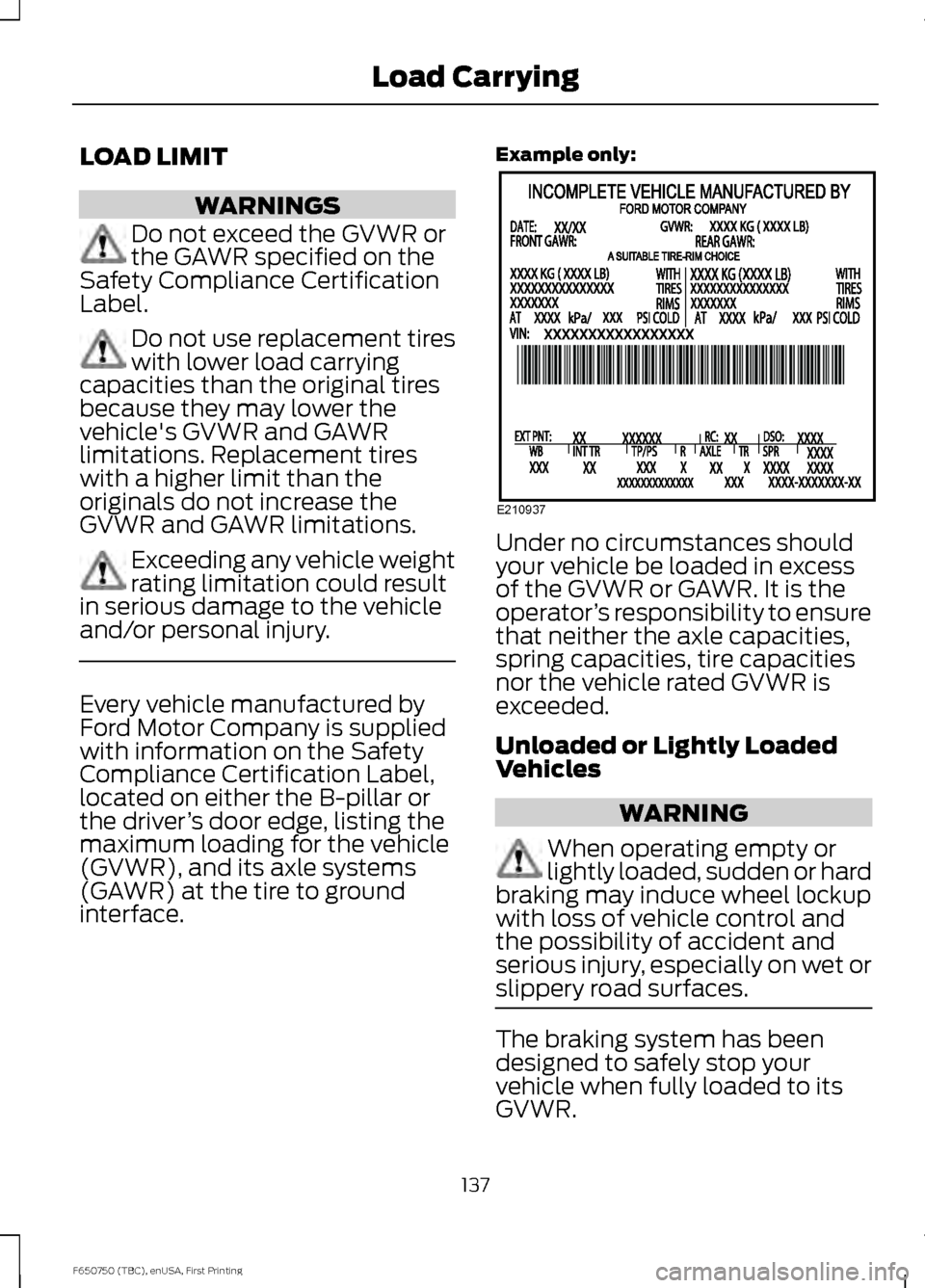
and/or personal injury. Every vehicle manufactured by
Ford Motor Company is supplied
with information on the Safety
Compliance Certification Label,
located on either the B-pillar or
the driver
’s door edge, listing the
maximum loading for the vehicle
(GVWR), and its axle systems
(GAWR) at the tire to ground
interface. Example only:
Under no circumstances should
your vehicle be loaded in excess
of the GVWR or GAWR. It is the
operator
’s responsibility to ensure
that neither the axle capacities,
spring capacities, tire capacities
nor the vehicle rated GVWR is
exceeded.
Unloaded or Lightly Loaded
Vehicles WARNING
When operating empty or
lightly loaded, sudden or hard
braking may induce wheel lockup
with loss of vehicle control and
the possibility of accident and
serious injury, especially on wet or
slippery road surfaces. The braking system has been
designed to safely stop your
vehicle when fully loaded to its
GVWR.
137
F650750 (TBC), enUSA, First Printing Load CarryingE210937
Page 141 of 379

AIR SUSPENSION (If Equipped)
Note: Do not operate your vehicle without
air in the suspension springs. Operating your
vehicle without air in the suspension springs
damages the suspension, degrades ride
performance and may cause property
damage.
The air suspension system automatically
adjusts to different loads to maintain a
constant frame height, allows for ease of
vehicle loading, provides improved vehicle
ride, and increased driver comfort.
Air Suspension Dump Button Note:
The suspension dumps air when the
ignition is in the accessory or on position,
but fills only when the ignition is in the on
position.
A button located on the instrument panel
controls the system. It operates only when
the ignition is in the accessory or on
position and the air tanks have sufficient
pressure to fill the air springs. When you
turn off the ignition, the suspension
remains in whatever state it was last set.
Pressing and holding the button for two
seconds exhausts air from the air springs,
lowering the frame for loading. Pressing
and holding the button for two seconds
fills the air springs so your vehicle remains
at normal ride height. System Indicator Light
The air suspension indicator light
illuminates when using the button to
release air pressure in the rear air springs.
Never drive your vehicle when the warning
lamp is illuminated and there is low (or no)
air pressure in the springs.
Connecting and Disconnecting a
Trailer with Air Suspension and Air
Suspension Dump Button
When connecting to a trailer:
•
Press and hold the button for two
seconds to exhaust air from the air
suspension system.
• Press and hold the button for two
seconds, and then raise the landing
gear after making the connection to
the trailer.
When disconnecting the trailer:
• Lower the landing gear, and then press
and hold the button for two seconds.
• Disconnect the brake hoses, trailer-side
and rear light connectors, then pull the
release lever on the fifth wheel.
You must fill the air springs before
operating with a trailer or operating in the
bobtail mode.
Suspension Conversions WARNING
When operating a loaded vehicle, the
driver must keep all adjustable axles
on the ground at all times, supporting
their share of the vehicle ’s load. Failure to
do so can overload other axles, tires,
wheels, springs, steering components,
brakes and frames, resulting in early
component failure, loss of vehicle control,
possible property damage and personal
injury. 138
F650750 (TBC), enUSA, First Printing Load CarryingE213409
Page 145 of 379
ESSENTIAL TOWING CHECKS
See Load limits in the Load Carrying
chapter for load specification terms found
on the tire label and Safety Compliance
label and instructions on calculating your
vehicle's load.
Remember to account for the trailer
tongue weight as part of your vehicle load
when calculating the total vehicle weight.
Hitches
Do not use a hitch that either clamps onto
the bumper or attaches to the axle. You
must distribute the load in your trailer so
that 10-15% of the total weight of the
trailer is on the tongue.
Safety Chains
Note: Do not attach safety chains to the
bumper.
Always connect the safety chains to the
frame or hook retainers of your vehicle
hitch.
To connect the safety chains, cross the
chains under the trailer tongue and allow
enough slack for turning tight corners. Do
not allow the chains to drag on the ground.
Trailer Brakes WARNING
Do not connect a trailer's hydraulic
brake system directly to your
vehicle's brake system. Your vehicle
may not have enough braking power and
your chances of having a collision greatly
increase. Electric brakes and manual, automatic or
surge-type trailer brakes are safe if you
install them properly and adjust them to
the manufacturer's specifications. The
trailer brakes must meet local and federal
regulations. The rating for the tow vehicle's braking
system operation is at the gross vehicle
weight rating, not the gross combined
weight rating.
Trailer Lamps
WARNING
Never connect any trailer lamp wiring
to the vehicle's tail lamp wiring; this
may damage the electrical system
resulting in fire. Contact your authorized
dealer as soon as possible for assistance
in proper trailer tow wiring installation.
Additional electrical equipment may be
required. Trailer lamps are required on most towed
vehicles. Make sure all running lights, brake
lights, turn signals and hazard lights are
working.
Before Towing a Trailer
Practice turning, stopping and backing up
to get the feel of your vehicle-trailer
combination before starting on a trip.
When turning, make wider turns so the
trailer wheels clear curbs and other
obstacles.
When Towing a Trailer
•
Check your hitch, electrical connections
and trailer wheel lug nuts thoroughly
after you have traveled 50 miles (80
kilometers).
• When stopped in congested or heavy
traffic during hot weather, place the
gearshift in position
P or position N to
aid engine and transmission cooling
and to help air conditioning
performance.
• Turn off the speed control with heavy
loads or in hilly terrain. The speed
control may turn off automatically
when you are towing on long, steep
grades.
142
F650750 (TBC), enUSA, First Printing Towing
Page 146 of 379
•
Shift to a lower gear when driving down
a long or steep hill. Do not apply the
brakes continuously, as they may
overheat and become less effective.
• If your transmission is equipped with
the Tow/Haul feature, use this feature
when towing. This provides engine
braking and helps eliminate excessive
transmission shifting for optimum fuel
economy and transmission cooling.
• Allow more distance for stopping with
a trailer attached. Anticipate stops and
brake gradually.
TRANSPORTING THE VEHICLE WARNING
To reduce the risk of personal injury
or property damage when manually
releasing the spring brakes, be sure
to block the wheels so the vehicle cannot
move once the brakes are released. Note:
Make sure to connect your vehicle
securely to the tow vehicle and that the tow
vehicle ’s parking brakes are set before
releasing the disabled vehicle ’s spring
brakes.
Before moving the disabled vehicle, check
for adequate road clearance of vehicle
components. If possible, unload the
disabled vehicle before towing. This
reduces any abnormal load to the vehicle
components resulting from the towing
procedures. Before towing, make sure to
release the parking brake fully. You can
reset the spring-actuated type parking
brake by recharging the air system with at
least 64 psi (441 kPa) of air. If the brake
system does not retain air pressure, then
you must release the spring brakes
manually. See
Parking Brake (page 121). Towing the Vehicle with the Front
Wheels Suspended
Note:
To avoid transmission damage, do
not tow your vehicle even a short distance
without suspending rear wheels or removing
the axle shafts or driveshaft.
Note: When towing a vehicle equipped with
a tandem axle from the front, raise the
forward rear axle so it can clear the road
surface and secure it to the frame with
chains or U-bolts, allowing only the rear rear
axle to contact the road surface. Remove
axle shafts from the rear rear axle assembly.
Cover the wheel hub ends to prevent loss
of axle lubricant and entrance of
contaminants. Use extreme care in securing
the chains or U-bolts to avoid possible
damage to the brake lines, hoses or other
components.
When it is necessary to tow a vehicle with
the front wheels suspended, take extra
precautions to avoid transmission or
differential damage:
• Remove the axle shafts from the axle
assembly to prevent the wheels from
driving the differential and the
transmission.
• Cover the wheel hub ends to prevent
loss of axle lubricant and entrance of
other contaminants. If you do not
remove the axle shafts, removal of the
driveshaft is required.
Towing the Vehicle with the Rear
Wheels Suspended
Note: To avoid damage to the cab roof or
air deflector when towing your vehicle
backward (rear wheels suspended), remove
the air deflector.
Whenever possible, it is preferable to tow
a disabled vehicle from the rear by raising
the rear of the chassis. When towing a
vehicle with the rear of the chassis
suspended, you must lock the front wheels
in the straight-ahead position.
143
F650750 (TBC), enUSA, First Printing Towing
Page 147 of 379
Towing Vehicles Equipped with a
Driver-controlled Differential Lock
Note:
If you have to tow your vehicle to a
service facility with the drive axle wheels on
the ground, it is necessary to remove the
axle shafts before towing your vehicle.
Removing Axle Shafts before Towing
1. Shift the main differential to the unlocked (disengaged) position; the
differential lock light turns off.
2. Remove the cap screws and washers or stud nuts and washers from flanges
of both axle shafts.
3. Loosen the tapered dowels in the flanges of both axle shafts by holding
a 1 ½-inch diameter brass drift or
hammer against the axle shaft center
and hitting it with a five or six pound
hammer.
Note: Do not use a chisel or wedge to
loosen the axle shafts and dowels. Use of
a chisel or wedge can damage the hub, axle
shafts and oil seals.
4. Remove the tapered dowels and both axle shafts from the axle assembly.
5. Assemble a cover over openings of both wheel ends to prevent loss of
lubricant and keep dirt away from the
wheel bearing cavities.
Note: One of the axle shafts has two sets
of splines. One set to engage with the
differential side gear and one set to engage
with the shift collar for the differential lock.
It may be necessary to rotate the shaft
slightly to align the gear spline teeth with
the shift collar teeth in order to remove the
axle shaft.
Installing the Axle Shafts
1. Remove the covers from the wheel ends.
2. Shift the differential lock to the unlocked (disengaged) position. 3. Install the axle shafts as outlined in
Steps 4 through 10.
4. Place the gaskets on the wheel hub studs.
5. Push the right-hand axle shaft and gasket into the wheel end and housing
until the shaft stops against the
differential shift collar.
6. Push down and in on the axle shaft flange and rotate the shaft until the
splines of the shaft and shift collar are
engaged.
7. Push the axle shaft further into the housing until the shaft stops against
the differential side gear.
8. Push down on the axle shaft flange and
rotate the shaft until the splines of the
shaft and side gear engage.
9. Push the axle shaft completely into the
housing until the axle shaft flange and
the gasket are flush against the wheel
hub.
10. Install the left-hand axle shaft and gasket into the wheel end.
11. If tapered dowels are required, install
them at each stud and into the flange
of the axle shaft. Use a punch or drift
and hammer, if needed.
12. Install the fasteners and tighten to correct torque value. See the
Workshop Manual.
FIFTH WHEEL OPERATION WARNINGS
Failure to follow the fifth wheel
manufacturer
’s instructions for
hooking and unhooking as well as
sliding the fifth wheel could result in an
accident, personal injury or death.
144
F650750 (TBC), enUSA, First Printing Towing