wheel FORD F650 2016 13.G Owner's Guide
[x] Cancel search | Manufacturer: FORD, Model Year: 2016, Model line: F650, Model: FORD F650 2016 13.GPages: 379, PDF Size: 4.8 MB
Page 148 of 379
WARNINGS
When the tractor and trailer are
parked unattended, the trailer brake
hand control should never be used
to apply the brake, since air may leak from
the system, allowing vehicle movement,
resulting in possible property damage,
personal injury or death. Before hook-up, make sure:
•
The fifth wheel jaws are fully open.
• The fifth wheel is fully tilted back to
prevent body damage when the tractor
is backed under a trailer.
• You block the trailer wheels and adjust
and apply the trailer spring brakes.
Never chase a trailer.
• The brake hoses and light cords are
clear of the fifth wheel.
Hook-up
1. Back the tractor squarely under the trailer, engaging the fifth-wheel jaws
on the kingpin. Always back up slowly;
make sure the trailer is neither too high
nor too low. Avoid backing under the
trailer from an angle.
2. Connect the service and emergency brake hoses and trailer light connector.
3. Inspect the jaws of the fifth wheel to be sure they have fully closed on the
trailer kingpin and the trailer plate is
resting securely on the fifth wheel.
4. Make sure the coupler release lever is in the locked position.
5. Charge the trailer brake system. Set the trailer brakes, with either the hand
valve or tractor protection valve. Pull
against the trailer for an extra check of
proper hook-up. Do not pull hard
enough to damage or strain the
equipment.
6. Set the tractor parking brakes and fully
raise the trailer landing gear. 7.
Check the operation of all trailer lights
and correct any lights that may be
faulty.
Un-hook
1. Try to keep the tractor and trailer in a straight line.
2. Apply the parking brakes.
3. Lower the trailer landing gear, making sure it is on solid, level ground. The
weight of the trailer is to be on the
landing gear.
4. Block the trailer wheels.
5. Disconnect the brake hoses and light cords. Be sure hoses and cords are
clear.
6. Pull coupler release lever to disengage
the fifth wheel jaws.
7. Release the tractor parking brakes.
8. Pull out from the trailer slowly, allowing
the landing gear to take the load
gradually.
145
F650750 (TBC), enUSA, First Printing Towing
Page 150 of 379
Parking
WARNING
When parking your vehicle, do not
leave the transmission in gear; if the
key is in the on position and the
vehicle rolls, the engine could start. Failure
to follow these instructions could result in
an unattended vehicle moving, possibly
causing personal injury or property
damage. Always use the parking brake. When
parking on a grade, block the wheels and
turn the front wheels to one side so that if
your vehicle rolls, the front tires act against
the curb to stop your vehicle. The front
wheels are more effective at stopping a
rolling vehicle than the rear wheels.
ECONOMICAL DRIVING
Your fuel economy is affected by several
things, such as how you drive, the
conditions you drive under, and how you
maintain your vehicle.
You may improve your fuel economy by
keeping these things in mind:
•
Accelerate and slow down in a smooth,
moderate fashion.
• Drive at steady speeds without
stopping.
• Anticipate stops; slowing down may
eliminate the need to stop.
• Close the windows for high-speed
driving.
• Drive at reasonable speeds (traveling
at 55 mph [88 km/h] uses 15% less
fuel than traveling at 65 mph [105
km/h]).
• Keep the tires properly inflated and use
only the recommended size. •
Use the recommended engine oil.
• Perform all regularly scheduled
maintenance.
Avoid these actions; they reduce your fuel
economy:
• Sudden accelerations or hard
accelerations.
• Warm up your vehicle on cold
mornings.
• Use the air conditioner or front
defroster.
• Use the speed control in hilly terrain.
• Rest your foot on the brake pedal while
driving.
• Carry unnecessary weight
(approximately 1 mpg [0.4 km/L] is
lost for every 400 lb [180 kilogram] of
weight carried).
• Driving with the wheels out of
alignment.
Conditions
• Adding certain accessories to your
vehicle (for example bug deflectors,
rollbars, light bars, running boards, ski
racks or luggage racks) may reduce
fuel economy.
• Using fuel blended with alcohol may
lower fuel economy.
• Fuel economy may decrease with lower
temperatures during the first 8– 10
miles (12 –16 kilometers) of driving.
• Driving on flat terrain offers improved
fuel economy as compared to driving
on hilly terrain.
• Transmissions give their best fuel
economy when operated in the top
cruise gear and with steady pressure
on the gas pedal.
147
F650750 (TBC), enUSA, First Printing Driving Hints
Page 153 of 379
Operation in Snow and Rain
Vehicle operation in heavy snowfall or
extreme rain conditions may feed
excessive amounts of snow or water into
the air intake system. This could plug the
air filter with snow and may cause the
engine to lose power and possibly shut
down.
We recommend the following actions after
operating your vehicle up to 199 mi
(320 km) in snowfall or extreme rain:
• Snow: At the earliest opportunity, open
the hood and clear all the snow and ice
from the air filter housing inlet (do not
remove the foam filter) and reset the
air filter restriction gauge.
Note: Removal of the foam filter degrades
your vehicle performance during snow and
hot weather conditions.
• Extreme rain: The air filter dries after
about 15– 30 minutes at highway
speeds. At the earliest opportunity,
open the hood and reset the air filter
restriction gauge.
DRIVING THROUGH WATER WARNING
Do not drive through flowing or deep
water as you may lose control of your
vehicle.
Note:
Driving through standing water can
cause vehicle damage.
Note: Engine damage can occur if water
enters the air filter.
Before driving through standing water,
check the depth. Never drive through water
that is higher than the bottom of the wheel
hubs. When driving through standing water, drive
very slowly and do not stop your vehicle.
Your brake performance and traction may
be limited. After driving through water and
as soon as it is safe to do so:
•
Lightly press the brake pedal to dry the
brakes and to check that they work.
• Check that the horn works.
• Check that the exterior lights work.
• Turn the steering wheel to check that
the steering power assist works.
Operation in Standing Water
Ingestion of water into the diesel engine
can result in immediate and severe
damage to the engine. If driving through
water, slow down to avoid splashing water
into the intake. If the engine stalls, and you
suspect ingestion of water into the engine,
do not try to restart the engine. Consult
your dealer for service immediately.
Your fuel tank vents to the atmosphere by
valves on top of the tank and through the
fuel cap. If water reaches the top of the
tank, the valves may pull water into the
fuel tank. Water in the fuel can cause
performance issues and damage the fuel
injection system.
150
F650750 (TBC), enUSA, First Printing Driving HintsE176913
Page 155 of 379
Canadian roadside coverage and benefits
may differ from the U.S. coverage. If you
require more information, please refer to
the coverage section of your warranty
guide, call us in Canada at
1-800-665-2006, or visit our website at
www.ford.ca.
Sykes Assistance Services Corporation
administers the Roadside Assistance
program. You must receive covered
services in Canada or the continental
United States. Coverage extends to
vehicles that use public, non-seasonal,
annually traveled roadways. Roadside
Assistance coverage does not extend to
vehicles involved in cross-country driving,
logging, autocross and any other form of
off-road use. Well maintained roads and
surfaces help ensure safe travel for the
supplier, and allow their representatives
to perform service as per the standard
operating procedures.
In Remote Locations
If our supplier cannot take your vehicle by
road to the nearest authorized dealership,
transportation by rail or water may be
necessary. The program covers a tow to
the dock or rail terminal and also to the
dealership at the end of the trip.
For rail or water transportation, however,
contact your authorized dealer to confirm
if you are eligible for additional coverage
before you authorize or pay for the service.
Call Ford Roadside Assistance at
1-800-665-2006 for additional
information.
HAZARD WARNING FLASHERS
Note:
The hazard warning flashers will
operate when the ignition is in any position
or if the key is not in the ignition. If used
when the engine is not running, the battery
will lose charge. As a result, there may be
insufficient power to restart your engine. In some models, the hazard
flasher control is located on the
instrument panel.
In other models, this feature is located on
the steering column, just behind the
steering wheel. Use your hazard warning flashers when
your vehicle is creating a safety hazard for
other motorists.
•
Press the flasher control and all front
and rear direction indicators flash.
• Press the flasher control again to turn
them off.
FUEL SHUTOFF WARNING
Failure to inspect and, if necessary,
repair fuel leaks after a collision may
increase the risk of fire and serious
injury. Ford Motor Company recommends
that the fuel system be inspected by an
authorized dealer after any collision. 152
F650750 (TBC), enUSA, First Printing Roadside EmergenciesE142663 E161463
Page 171 of 379
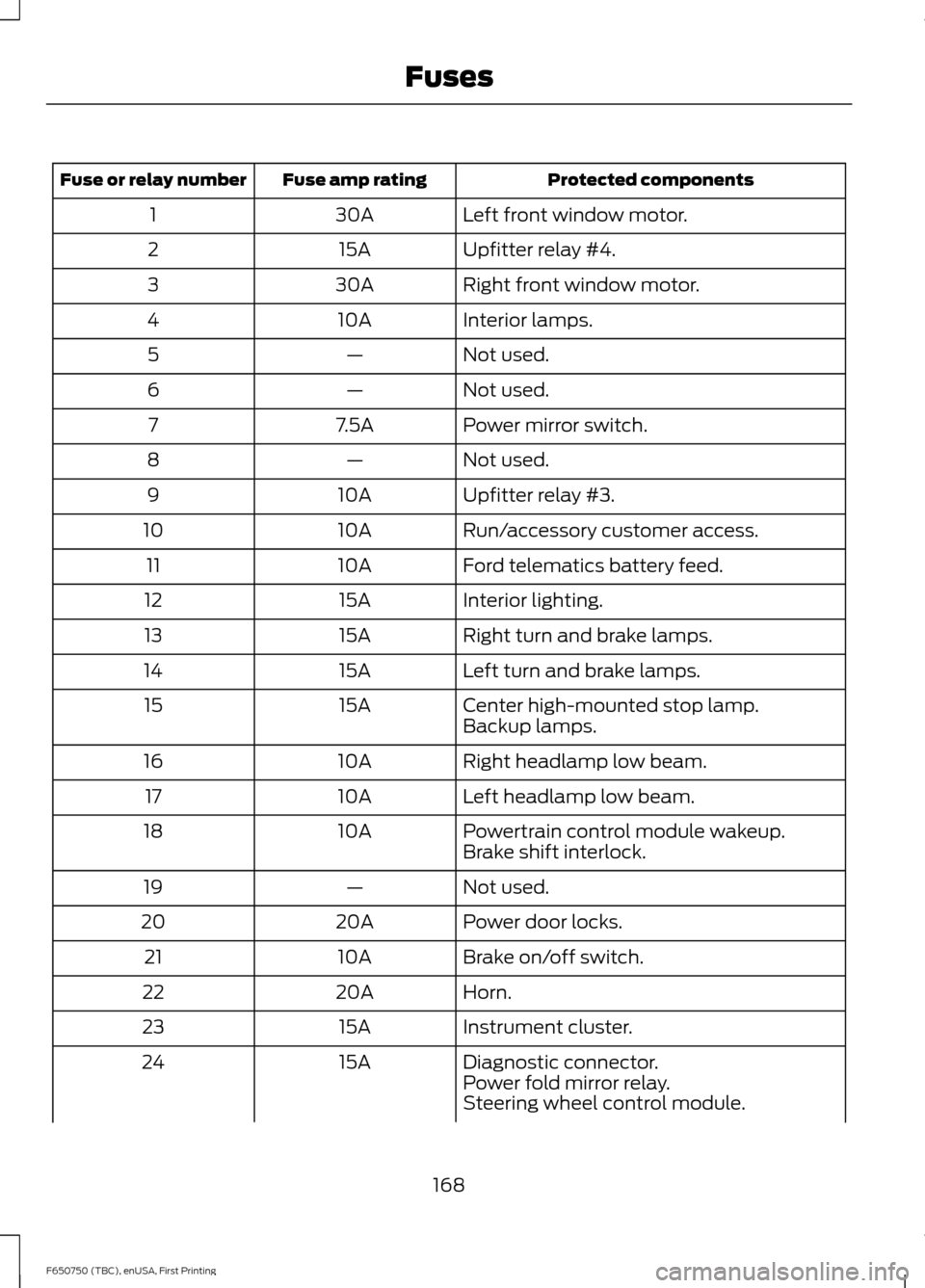
Protected components
Fuse amp rating
Fuse or relay number
Left front window motor.
30A
1
Upfitter relay #4.
15A
2
Right front window motor.
30A
3
Interior lamps.
10A
4
Not used.
—
5
Not used.
—
6
Power mirror switch.
7.5A
7
Not used.
—
8
Upfitter relay #3.
10A
9
Run/accessory customer access.
10A
10
Ford telematics battery feed.
10A
11
Interior lighting.
15A
12
Right turn and brake lamps.
15A
13
Left turn and brake lamps.
15A
14
Center high-mounted stop lamp.
15A
15
Backup lamps.
Right headlamp low beam.
10A
16
Left headlamp low beam.
10A
17
Powertrain control module wakeup.
10A
18
Brake shift interlock.
Not used.
—
19
Power door locks.
20A
20
Brake on/off switch.
10A
21
Horn.
20A
22
Instrument cluster.
15A
23
Diagnostic connector.
15A
24
Power fold mirror relay.
Steering wheel control module.
168
F650750 (TBC), enUSA, First Printing Fuses
Page 172 of 379
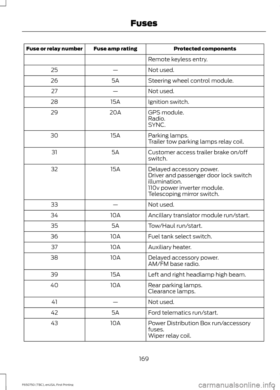
Protected components
Fuse amp rating
Fuse or relay number
Remote keyless entry.
Not used.
—
25
Steering wheel control module.
5A
26
Not used.
—
27
Ignition switch.
15A
28
GPS module.
20A
29
Radio.
SYNC.
Parking lamps.
15A
30
Trailer tow parking lamps relay coil.
Customer access trailer brake on/off
switch.
5A
31
Delayed accessory power.
15A
32
Driver and passenger door lock switch
illumination.
110v power inverter module.
Telescoping mirror switch.
Not used.
—
33
Ancillary translator module run/start.
10A
34
Tow/Haul run/start.
5A
35
Fuel tank select switch.
10A
36
Auxiliary heater.
10A
37
Delayed accessory power.
10A
38
AM/FM base radio.
Left and right headlamp high beam.
15A
39
Rear parking lamps.
10A
40
Clearance lamps.
Not used.
—
41
Ford telematics run/start.
5A
42
Power Distribution Box run/accessory
fuses.
10A
43
Wiper relay coil.
169
F650750 (TBC), enUSA, First Printing Fuses
Page 174 of 379
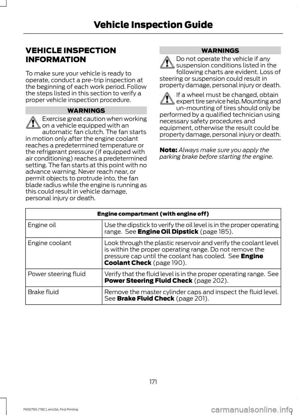
VEHICLE INSPECTION
INFORMATION
To make sure your vehicle is ready to
operate, conduct a pre-trip inspection at
the beginning of each work period. Follow
the steps listed in this section to verify a
proper vehicle inspection procedure.
WARNINGS
Exercise great caution when working
on a vehicle equipped with an
automatic fan clutch. The fan starts
in motion only after the engine coolant
reaches a predetermined temperature or
the refrigerant pressure (if equipped with
air conditioning) reaches a predetermined
setting. The fan starts at this point with no
advance warning. Never reach near, or
permit objects to protrude into, the fan
blade radius while the engine is running as
this could result in vehicle damage,
personal injury or death. WARNINGS
Do not operate the vehicle if any
suspension conditions listed in the
following charts are evident. Loss of
steering or suspension could result in
property damage, personal injury or death. If a wheel must be changed, obtain
expert tire service help. Mounting and
un-mounting of tires should only be
performed by a qualified technician using
necessary safety procedures and
equipment, otherwise the result could be
property damage, personal injury or death. Note:
Always make sure you apply the
parking brake before starting the engine. Engine compartment (with engine off)
Use the dipstick to verify the oil level is in the proper operating
range. See Engine Oil Dipstick (page 185).
Engine oil
Look through the plastic reservoir and verify the coolant level
is within the proper operating range. Do not remove the
pressure cap until the coolant has cooled. See
Engine
Coolant Check (page 190).
Engine coolant
Verify that the fluid level is in the proper operating range. See
Power Steering Fluid Check
(page 202).
Power steering fluid
Remove the master cylinder caps and inspect the fluid level.
See
Brake Fluid Check (page 201).
Brake fluid
171
F650750 (TBC), enUSA, First Printing Vehicle Inspection Guide
Page 175 of 379
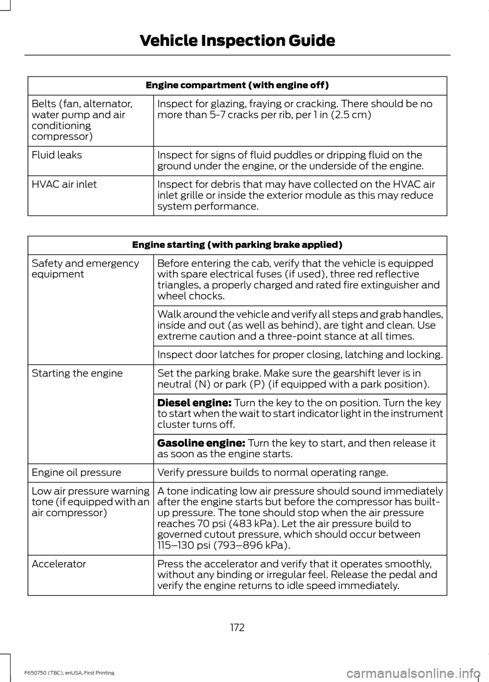
Engine compartment (with engine off)
Inspect for glazing, fraying or cracking. There should be no
more than 5-7 cracks per rib, per 1 in (2.5 cm)
Belts (fan, alternator,
water pump and air
conditioning
compressor)
Inspect for signs of fluid puddles or dripping fluid on the
ground under the engine, or the underside of the engine.
Fluid leaks
Inspect for debris that may have collected on the HVAC air
inlet grille or inside the exterior module as this may reduce
system performance.
HVAC air inlet Engine starting (with parking brake applied)
Before entering the cab, verify that the vehicle is equipped
with spare electrical fuses (if used), three red reflective
triangles, a properly charged and rated fire extinguisher and
wheel chocks.
Safety and emergency
equipment
Walk around the vehicle and verify all steps and grab handles,
inside and out (as well as behind), are tight and clean. Use
extreme caution and a three-point stance at all times.
Inspect door latches for proper closing, latching and locking.
Set the parking brake. Make sure the gearshift lever is in
neutral (N) or park (P) (if equipped with a park position).
Starting the engine
Diesel engine:
Turn the key to the on position. Turn the key
to start when the wait to start indicator light in the instrument
cluster turns off.
Gasoline engine:
Turn the key to start, and then release it
as soon as the engine starts.
Verify pressure builds to normal operating range.
Engine oil pressure
A tone indicating low air pressure should sound immediately
after the engine starts but before the compressor has built-
up pressure. The tone should stop when the air pressure
reaches
70 psi (483 kPa). Let the air pressure build to
governed cutout pressure, which should occur between
115– 130 psi (793–896 kPa)
.
Low air pressure warning
tone (if equipped with an
air compressor)
Press the accelerator and verify that it operates smoothly,
without any binding or irregular feel. Release the pedal and
verify the engine returns to idle speed immediately.
Accelerator
172
F650750 (TBC), enUSA, First Printing Vehicle Inspection Guide
Page 176 of 379
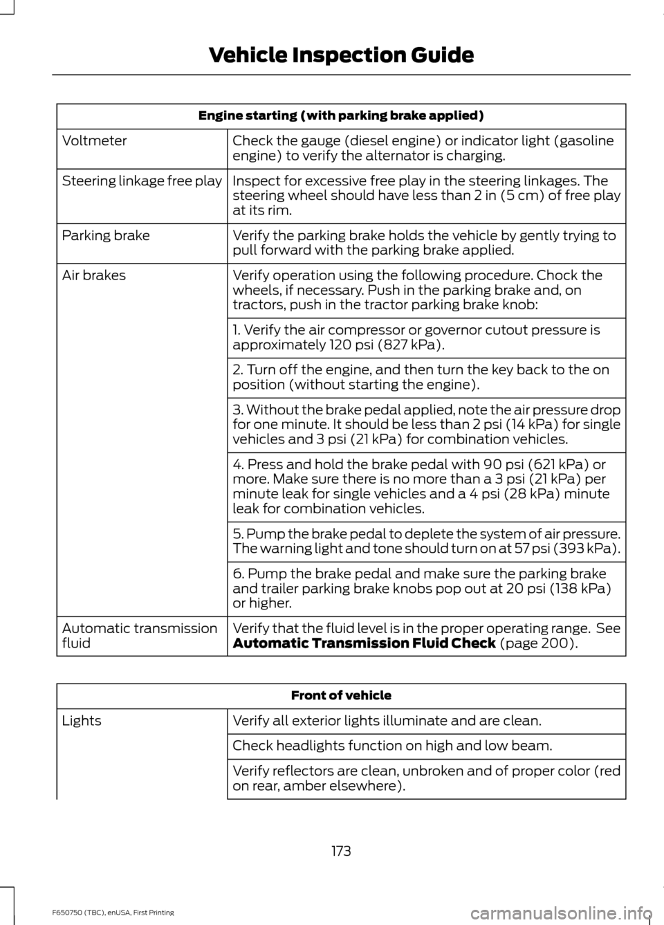
Engine starting (with parking brake applied)
Check the gauge (diesel engine) or indicator light (gasoline
engine) to verify the alternator is charging.
Voltmeter
Inspect for excessive free play in the steering linkages. The
steering wheel should have less than 2 in (5 cm) of free play
at its rim.
Steering linkage free play
Verify the parking brake holds the vehicle by gently trying to
pull forward with the parking brake applied.
Parking brake
Verify operation using the following procedure. Chock the
wheels, if necessary. Push in the parking brake and, on
tractors, push in the tractor parking brake knob:
Air brakes
1. Verify the air compressor or governor cutout pressure is
approximately 120 psi (827 kPa).
2. Turn off the engine, and then turn the key back to the on
position (without starting the engine).
3. Without the brake pedal applied, note the air pressure drop
for one minute. It should be less than 2 psi (14 kPa) for single
vehicles and
3 psi (21 kPa) for combination vehicles.
4. Press and hold the brake pedal with
90 psi (621 kPa) or
more. Make sure there is no more than a 3 psi (21 kPa) per
minute leak for single vehicles and a 4 psi (28 kPa) minute
leak for combination vehicles.
5. Pump the brake pedal to deplete the system of air pressure.
The warning light and tone should turn on at 57 psi (393 kPa).
6. Pump the brake pedal and make sure the parking brake
and trailer parking brake knobs pop out at
20 psi (138 kPa)
or higher.
Verify that the fluid level is in the proper operating range. See
Automatic Transmission Fluid Check
(page 200).
Automatic transmission
fluid Front of vehicle
Verify all exterior lights illuminate and are clean.
Lights
Check headlights function on high and low beam.
Verify reflectors are clean, unbroken and of proper color (red
on rear, amber elsewhere).
173
F650750 (TBC), enUSA, First Printing Vehicle Inspection Guide
Page 178 of 379
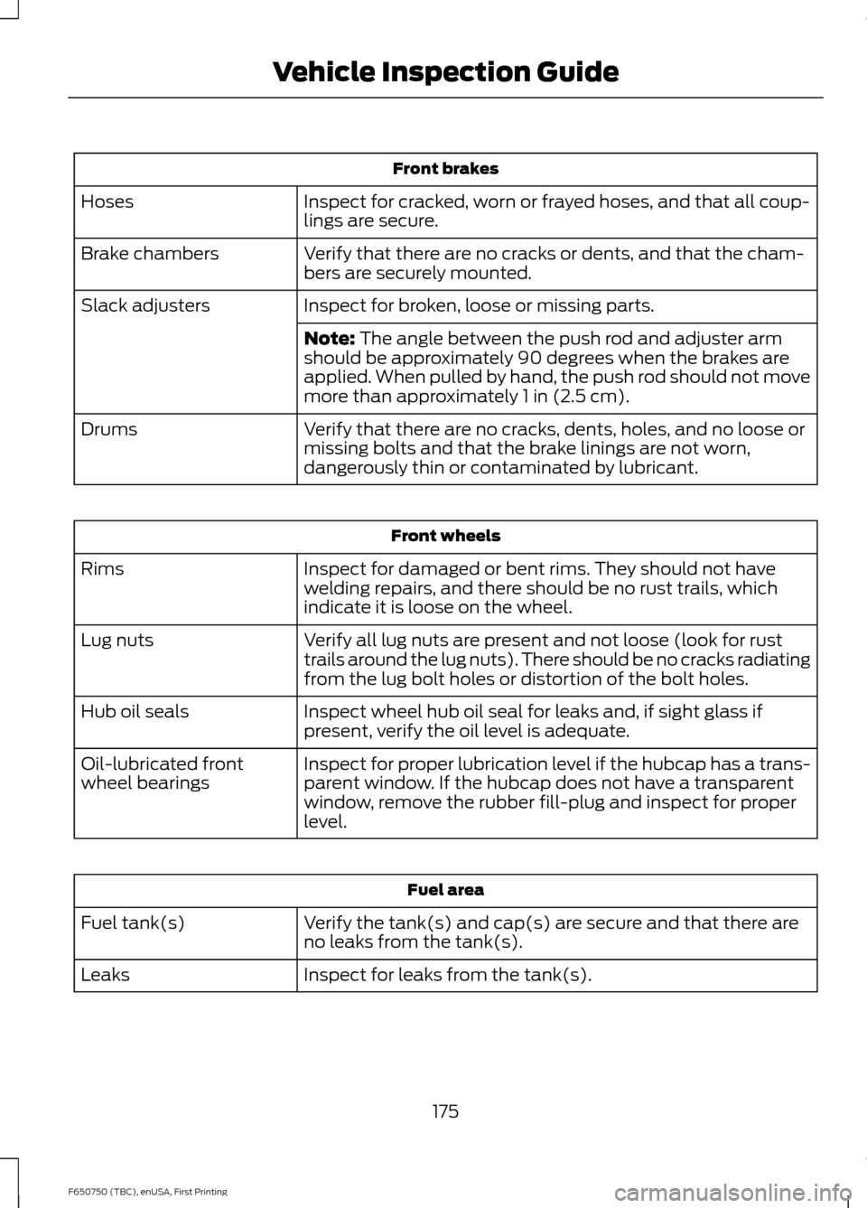
Front brakes
Inspect for cracked, worn or frayed hoses, and that all coup-
lings are secure.
Hoses
Verify that there are no cracks or dents, and that the cham-
bers are securely mounted.
Brake chambers
Inspect for broken, loose or missing parts.
Slack adjusters
Note: The angle between the push rod and adjuster arm
should be approximately 90 degrees when the brakes are
applied. When pulled by hand, the push rod should not move
more than approximately
1 in (2.5 cm).
Verify that there are no cracks, dents, holes, and no loose or
missing bolts and that the brake linings are not worn,
dangerously thin or contaminated by lubricant.
Drums Front wheels
Inspect for damaged or bent rims. They should not have
welding repairs, and there should be no rust trails, which
indicate it is loose on the wheel.
Rims
Verify all lug nuts are present and not loose (look for rust
trails around the lug nuts). There should be no cracks radiating
from the lug bolt holes or distortion of the bolt holes.
Lug nuts
Inspect wheel hub oil seal for leaks and, if sight glass if
present, verify the oil level is adequate.
Hub oil seals
Inspect for proper lubrication level if the hubcap has a trans-
parent window. If the hubcap does not have a transparent
window, remove the rubber fill-plug and inspect for proper
level.
Oil-lubricated front
wheel bearings Fuel area
Verify the tank(s) and cap(s) are secure and that there are
no leaks from the tank(s).
Fuel tank(s)
Inspect for leaks from the tank(s).
Leaks
175
F650750 (TBC), enUSA, First Printing Vehicle Inspection Guide