FORD F650/750 2019 Owners Manual
Manufacturer: FORD, Model Year: 2019, Model line: F650/750, Model: FORD F650/750 2019Pages: 387, PDF Size: 4.78 MB
Page 251 of 387
WARNING: To reduce the
risk of serious injury, when
mounting replacement tires and
wheels, you should not exceed
the maximum pressure indicated
on the sidewall of the tire to set
the beads without additional
precautions listed below. If the
beads do not seat at the
maximum pressure indicated,
re-lubricate and try again. WARNING: When inflating
the tire for mounting pressures
up to
20 psi (1.38 bar) greater
than the maximum pressure on
the tire sidewall, the following
precautions must be taken to
protect the person mounting the
tire: WARNING:
To reduce the
risk of serious injury, when
mounting replacement tires and
wheels, you should not exceed
the maximum pressure indicated
on the sidewall of the tire to set
the beads without additional
precautions listed below. If the
beads do not seat at the
maximum pressure indicated,
re-lubricate and try again.
• Stand at a minimum of
12 ft
(3.66 m) away from the wheel
and tire assembly.
• Use both eye and ear
protection. WARNING: For a mounting
pressure more than
20 psi
(1.38 bar) greater than the
maximum pressure, a Ford
dealer or other tire service
professional should do the
mounting. WARNING:
Always inflate
steel carcass tires with a remote
air fill with the person inflating
standing at a minimum of
12 ft
(3.66 m) away from the wheel
and tire assembly.
Important: Remember to replace
the wheel valve stems when the
road tires are replaced on your
vehicle
It is recommended that the two
front tires or two rear tires
generally be replaced as a pair.
Replacing a Tire That is
Greenhouse Gas Certified
The tires installed on this vehicle
at the factory as original
equipment are certified for
Greenhouse Gas and Fuel
Efficiency regulations.
Replacement tires must be of
equal or lower rolling resistance
level (TRRL or Crr). Consult with
your tire supplier(s) for
appropriate replacement tires.
248
F650750 (TBC) , enUSA, Edition date: 201804, Second-Printing Wheels and Tires
Page 252 of 387
Safety Practices
WARNING: If your vehicle
is stuck in snow, mud or sand, do
not rapidly spin the tires;
spinning the tires can tear the
tire and cause an explosion. A
tire can explode in as little as
three to five seconds. WARNING: Do not spin the
wheels at over
34 mph
(55 km/h). The tires may fail and
injure a passenger or bystander.
Driving habits have a great deal
to do with your tire mileage and
safety.
• Observe posted speed limits
• Avoid fast starts, stops and
turns
• Avoid potholes and objects on
the road
• Do not run over curbs or hit the
tire against a curb when
parking
Highway Hazards
No matter how carefully you drive
there ’s always the possibility that
you may eventually have a flat tire
on the highway. Drive slowly to the
closest safe area out of traffic.
This may further damage the flat
tire, but your safety is more
important. If you feel a sudden vibration or
ride disturbance when driving, or
you suspect your tire or vehicle
has been damaged, immediately
reduce your speed. Drive with
caution until you can safely pull
off the road. Stop and inspect the
tires for damage. If a tire is
under-inflated or damaged,
deflate it, remove wheel and
replace it with your spare tire and
wheel. If you cannot detect a
cause, have the vehicle towed to
the nearest repair facility or tire
dealer to have the vehicle
inspected.
Tire and Wheel Alignment
A bad jolt from hitting a curb or
pothole can cause the front end
of your vehicle to become
misaligned or cause damage to
your tires. If your vehicle seems to
pull to one side when you’re
driving, the wheels may be out of
alignment. Have an authorized
dealer check the wheel alignment
periodically.
Wheel misalignment in the front
or the rear can cause uneven and
rapid treadwear of your tires and
should be corrected by an
authorized dealer. Front-wheel
drive vehicles and those with an
independent rear suspension may
require alignment of all four
wheels.
The tires should also be balanced
periodically. An unbalanced tire
and wheel assembly may result in
irregular tire wear.
249
F650750 (TBC) , enUSA, Edition date: 201804, Second-Printing Wheels and Tires
Page 253 of 387
Tire Rotation
Note:
If your tires show uneven
wear ask an authorized dealer to
check for and correct any wheel
misalignment, tire imbalance or
mechanical problem involved
before tire rotation.
Note: Your vehicle may be
equipped with a dissimilar spare
wheel and tire assembly. A
dissimilar spare wheel and tire
assembly is defined as a spare
wheel and tire assembly that is
different in brand, size or
appearance from the road tires and
wheels. If you have a dissimilar
spare wheel and tire assembly it is
intended for temporary use only
and should not be used in a tire
rotation.
Rotating your tires at the
recommended interval helps your
tires wear more evenly, providing
better tire performance and longer
tire life. Rear-wheel drive vehicles Dual rear wheel vehicles (six
tire rotation)
If your vehicle is equipped with
dual rear wheels it is
recommended that the front and
rear tires (in pairs) be rotated only
side to side. We do not
recommend splitting up the dual
rear wheels. Rotate them side to
side as a set. After tire rotation,
inflation pressures must be
adjusted for the tires new
positions in accordance with
vehicle requirements.
Sometimes irregular tire wear can
be corrected by rotating the tires.
250
F650750 (TBC) , enUSA, Edition date: 201804, Second-Printing Wheels and TiresE142548 E161439
Page 254 of 387
USING SNOW CHAINS
WARNING: Snow tires must be
the same size, load index, and speed
rating as those originally provided by
Ford. Use of any tire or wheel not
recommended by Ford can affect the
safety and performance of your vehicle,
which could result in an increased risk of
loss of vehicle control, vehicle rollover,
personal injury, and death. Additionally,
the use of non-recommended tires and
wheels could cause steering, suspension,
axle, transfer case, or power transfer unit
failure. It is also strongly advised to
follow the Ford recommended tire
inflation pressure found on the Safety
Compliance Certification Label (affixed
to either the door hinge pillar, door-latch
post, or the door edge that meets the
door-latch post, next to the driver ’s
seating position), or Tire Label which is
located on the B-Pillar or the edge of the
driver door. Failure to follow the tire
pressure recommendations can cause
uneven treadwear patterns and
adversely affect the way your vehicle
handles.
The tires on your vehicle have all-weather
treads to provide traction in rain and snow.
However, in some climates, you may need
to use snow tires and cables. If you need
to use cables, it is recommended that steel
wheels (of the same size and
specifications) be used, as cables may chip
aluminum wheels.
Note: The suspension insulation and
bumpers help prevent vehicle damage. Do
not remove these components from your
vehicle when using snow tires and chains.
Follow these guidelines when using snow
tires and chains: •
If possible, avoid fully loading your
vehicle.
• Use only SAE Class S chains.
• Install chains securely, verifying that
the chains do not touch any wiring,
brake lines or fuel lines.
• Drive cautiously. If you hear the chains
rub or bang against your vehicle, stop
and retighten the chains. If this does
not work, remove the chains to prevent
damage to your vehicle.
• Remove the tire chains when they are
no longer needed. Do not use tire
chains on dry roads.
If you have any questions regarding snow
chains or cables, please contact your
authorized dealer.
CHANGING A ROAD WHEEL
If you get a flat tire while driving, do not
apply the brake heavily. Instead, gradually
decrease your speed. Hold the steering
wheel firmly and slowly move to a safe
place on the side of the road.
Tire Change Procedure WARNING:
When one of the front
wheels is off the ground, the
transmission alone will not prevent the
vehicle from moving or slipping off the
jack, even if the transmission is in park
(P). WARNING:
To help prevent the
vehicle from moving when you change
a tire, be sure to place the transmission
in park (P), set the parking brake and
block (in both directions) the wheel that
is diagonally opposite (other side and
end of the vehicle) to the tire being
changed.
251
F650750 (TBC) , enUSA, Edition date: 201804, Second-Printing Wheels and Tires
Page 255 of 387
WARNING: Never get underneath
a vehicle that is supported only by a jack.
If the vehicle slips off the jack, you or
someone else could be seriously injured. WARNING:
Do not attempt to
change a tire on the side of the vehicle
close to moving traffic. Pull far enough
off the road to avoid the danger of being
hit when operating the jack or changing
the wheel.
Note: Passengers should not remain in the
vehicle when the vehicle is being jacked.
Park on a level surface, set the parking
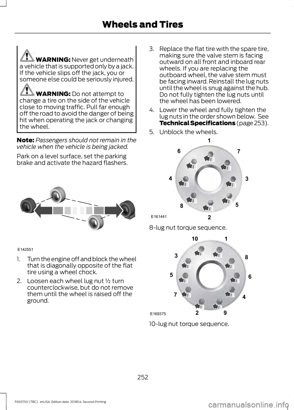
brake and activate the hazard flashers. 1.
Turn the engine off and block the wheel
that is diagonally opposite of the flat
tire using a wheel chock.
2. Loosen each wheel lug nut ½ turn counterclockwise, but do not remove
them until the wheel is raised off the
ground. 3.
Replace the flat tire with the spare tire,
making sure the valve stem is facing
outward on all front and inboard rear
wheels. If you are replacing the
outboard wheel, the valve stem must
be facing inward. Reinstall the lug nuts
until the wheel is snug against the hub.
Do not fully tighten the lug nuts until
the wheel has been lowered.
4. Lower the wheel and fully tighten the lug nuts in the order shown below. See
Technical Specifications (page 253).
5. Unblock the wheels. 8-lug nut torque sequence.
10-lug nut torque sequence.
252
F650750 (TBC) , enUSA, Edition date: 201804, Second-Printing Wheels and TiresE142551 E161441
13
4
27
6
5
8 1
2
3
4
5
6
7 8
9
10
E169375
Page 256 of 387
TECHNICAL SPECIFICATIONS
Wheel Lug Nut Torque Specifications
WARNING: When you install a wheel, always remove any corrosion, dirt or foreign
materials present on the mounting surfaces of the wheel or the surface of the wheel
hub, brake drum or brake disc that contacts the wheel. Make sure to secure any fasteners
that attach the rotor to the hub so they do not interfere with the mounting surfaces of
the wheel. Installing wheels without correct metal-to-metal contact at the wheel
mounting surfaces can cause the wheel nuts to loosen and the wheel to come off while
your vehicle is in motion, resulting in loss of vehicle control, personal injury or death. lb.ft (Nm)
1
Bolt size
450–500 lb.ft (610–678 Nm)
M22 x 1.5
1 Torque specifications are for nut and bolt threads free of dirt and rust. Use only Ford
recommended replacement fasteners.
On vehicles equipped with single rear wheels, retighten the lug nuts to the specified torque
at 100 miles (160 kilometers) after any wheel disturbance (such as tire rotation, changing
a flat tire, wheel removal).
On vehicles equipped with dual rear wheels, retighten the lug nuts to the specified torque
at 100 miles (160 kilometers) and again at 500 miles (800 kilometers) of new vehicle
operation and after any wheel disturbance (such as tire rotation, changing a flat tire,
wheel removal).
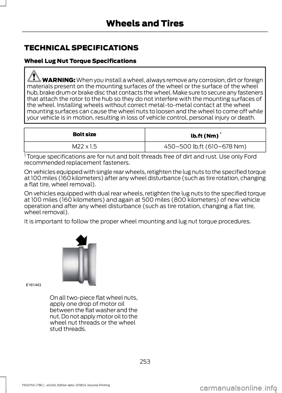
It is important to follow the proper wheel mounting and lug nut torque procedures. On all two-piece flat wheel nuts,
apply one drop of motor oil
between the flat washer and the
nut. Do not apply motor oil to the
wheel nut threads or the wheel
stud threads.
253
F650750 (TBC) , enUSA, Edition date: 201804, Second-Printing Wheels and TiresE161443
Page 257 of 387
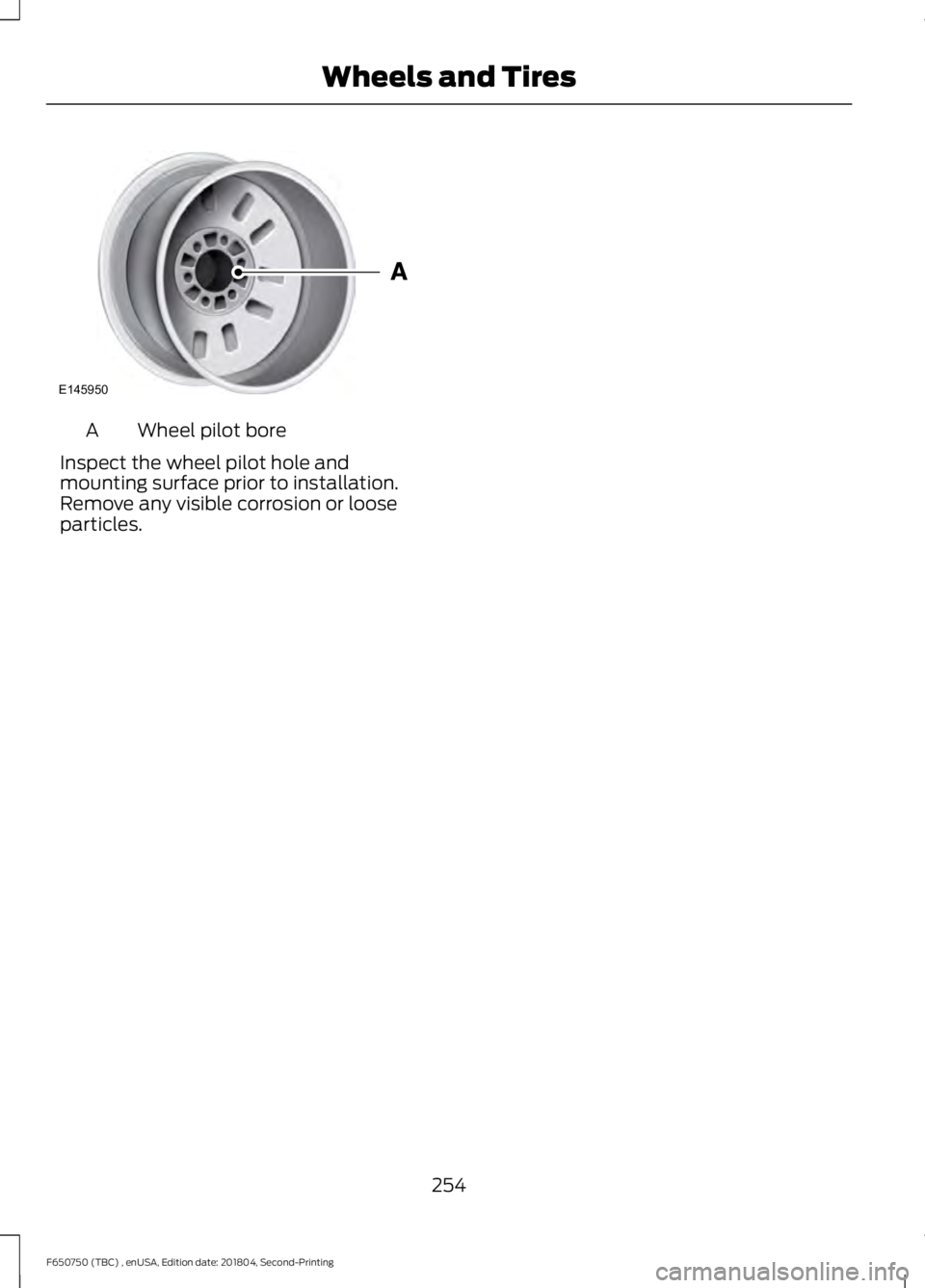
Wheel pilot bore
A
Inspect the wheel pilot hole and
mounting surface prior to installation.
Remove any visible corrosion or loose
particles.
254
F650750 (TBC) , enUSA, Edition date: 201804, Second-Printing Wheels and TiresE145950
Page 258 of 387
ENGINE SPECIFICATIONS - 6.7L DIESEL
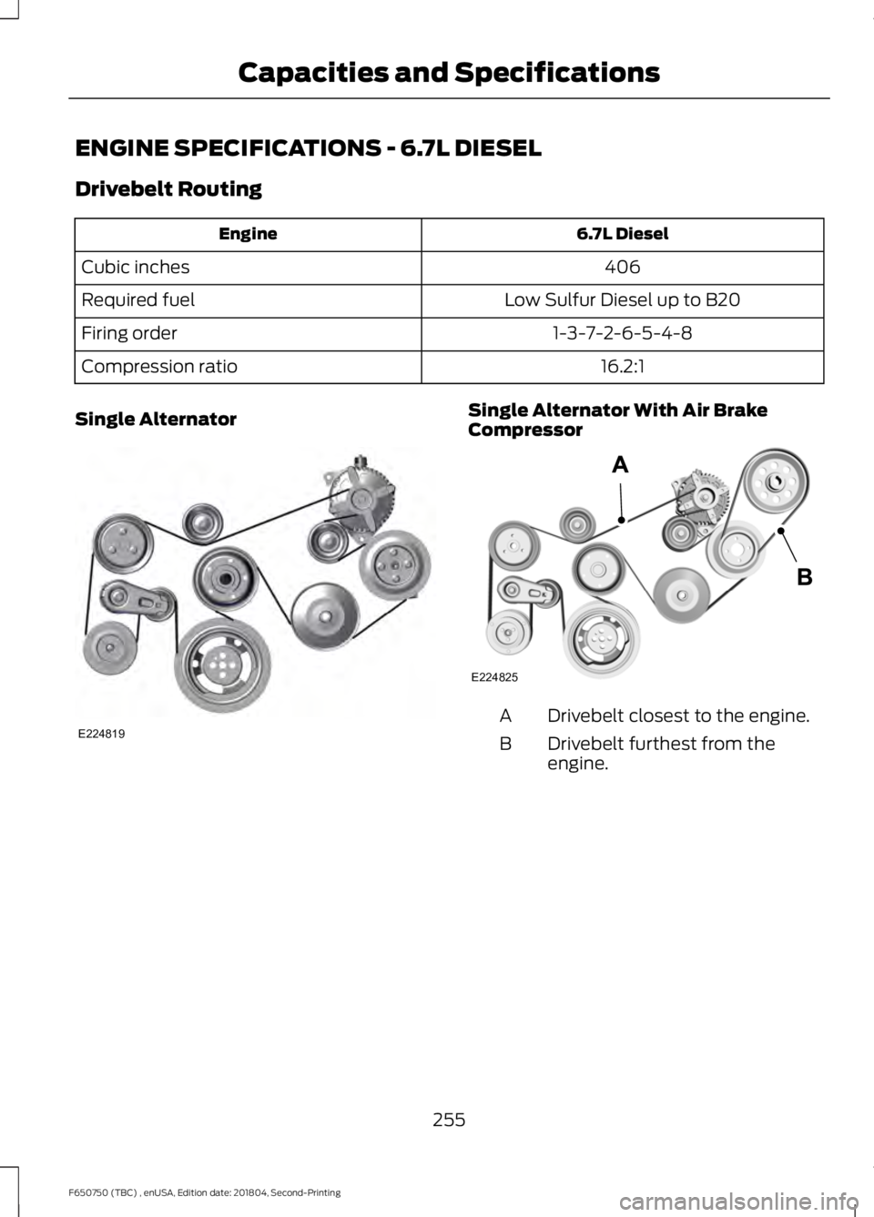
Drivebelt Routing
6.7L Diesel
Engine
406
Cubic inches
Low Sulfur Diesel up to B20
Required fuel
1-3-7-2-6-5-4-8
Firing order
16.2:1
Compression ratio
Single Alternator Single Alternator With Air Brake
Compressor
Drivebelt closest to the engine.
A
Drivebelt furthest from the
engine.
B
255
F650750 (TBC) , enUSA, Edition date: 201804, Second-Printing Capacities and SpecificationsE224819 E224825
Page 259 of 387
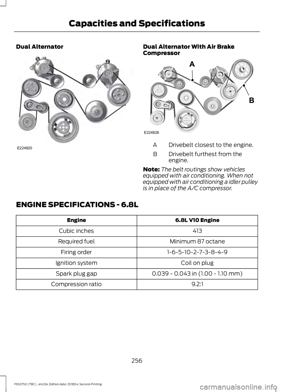
Dual Alternator Dual Alternator With Air Brake
Compressor
Drivebelt closest to the engine.
A
Drivebelt furthest from the
engine.
B
Note: The belt routings show vehicles
equipped with air conditioning. When not
equipped with air conditioning a idler pulley
is in place of the A/C compressor.
ENGINE SPECIFICATIONS - 6.8L 6.8L V10 Engine
Engine
413
Cubic inches
Minimum 87 octane
Required fuel
1-6-5-10-2-7-3-8-4-9
Firing order
Coil on plug
Ignition system
0.039 - 0.043 in (1.00 - 1.10 mm)
Spark plug gap
9.2:1
Compression ratio
256
F650750 (TBC) , enUSA, Edition date: 201804, Second-Printing Capacities and SpecificationsE224820 E224826
Page 260 of 387
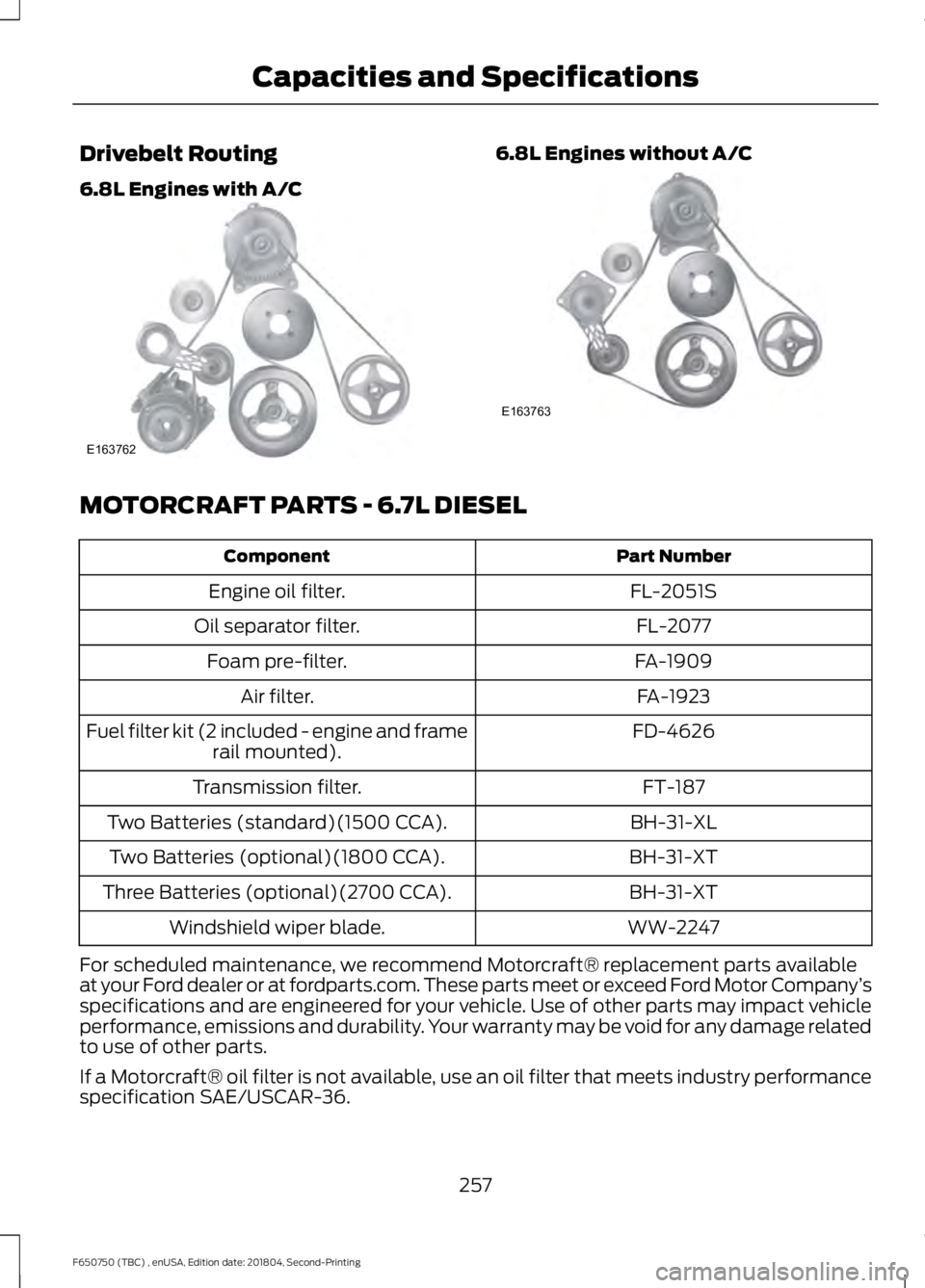
Drivebelt Routing
6.8L Engines with A/C 6.8L Engines without A/C
MOTORCRAFT PARTS - 6.7L DIESEL
Part Number
Component
FL-2051S
Engine oil filter.
FL-2077
Oil separator filter.
FA-1909
Foam pre-filter.
FA-1923
Air filter.
FD-4626
Fuel filter kit (2 included - engine and frame
rail mounted).
FT-187
Transmission filter.
BH-31-XL
Two Batteries (standard)(1500 CCA).
BH-31-XT
Two Batteries (optional)(1800 CCA).
BH-31-XT
Three Batteries (optional)(2700 CCA).
WW-2247
Windshield wiper blade.
For scheduled maintenance, we recommend Motorcraft® replacement parts available
at your Ford dealer or at fordparts.com. These parts meet or exceed Ford Motor Company ’s
specifications and are engineered for your vehicle. Use of other parts may impact vehicle
performance, emissions and durability. Your warranty may be void for any damage related
to use of other parts.
If a Motorcraft® oil filter is not available, use an oil filter that meets industry performance
specification SAE/USCAR-36.
257
F650750 (TBC) , enUSA, Edition date: 201804, Second-Printing Capacities and SpecificationsE163762 E163763