tow FORD F650/750 2019 Owner's Manual
[x] Cancel search | Manufacturer: FORD, Model Year: 2019, Model line: F650/750, Model: FORD F650/750 2019Pages: 387, PDF Size: 4.78 MB
Page 94 of 387

temperatures, and be clearly marked
Suitable for Use with Outdoor
Appliances. Do not use an indoor
extension cord outdoors. This could
result in an electric shock or become a
fire hazard.
• Use as short an extension cord as
possible.
• Do not use multiple extension cords.
• Make sure that when in operation, the
extension cord plug and heater cord
plug connections are free and clear of
water. This could cause an electric
shock or fire.
• Make sure your vehicle is parked in a
clean area, clear of combustibles.
• Make sure the heater, heater cord and
extension cord are firmly connected.
• Check for heat anywhere in the
electrical hookup once the system has
been operating for approximately 30
minutes.
• Make sure the system is unplugged and
properly stowed before starting and
driving your vehicle. Make sure the
protective cover seals the prongs of the
block heater cord plug when not in use.
• Make sure the heater system is
checked for proper operation before
winter.
Using the Engine Block Heater
The engine block heater plug is on the
right-hand side of the front bumper next
to the recovery hook. Open the hinged,
circular door and make sure the receptacle
terminals are clean and dry prior to use.
Clean them with a dry cloth if necessary. The heater uses 0.4 to 1.0 kilowatt-hours
of energy per hour of use. The system does
not have a thermostat. It achieves
maximum temperature after
approximately three hours of operation.
Using the heater longer than three hours
does not improve system performance and
unnecessarily uses electricity.
91
F650750 (TBC) , enUSA, Edition date: 201804, Second-Printing Starting and Stopping the Engine
Page 99 of 387
Do not use alcohol-based additives to
improve cetane quality, to prevent fuel
gelling or any other use. The use of alcohol
additives may result in damage to the fuel
injectors and system. See Capacities and
Specifications (page 261).
The Vehicle Warranty may not cover
repairs needed to correct the effects of
using an aftermarket product that does
not meet Ford specifications in your fuel.
FUEL QUALITY - GASOLINE
Choosing the Right Fuel Your vehicle is designed to operate on
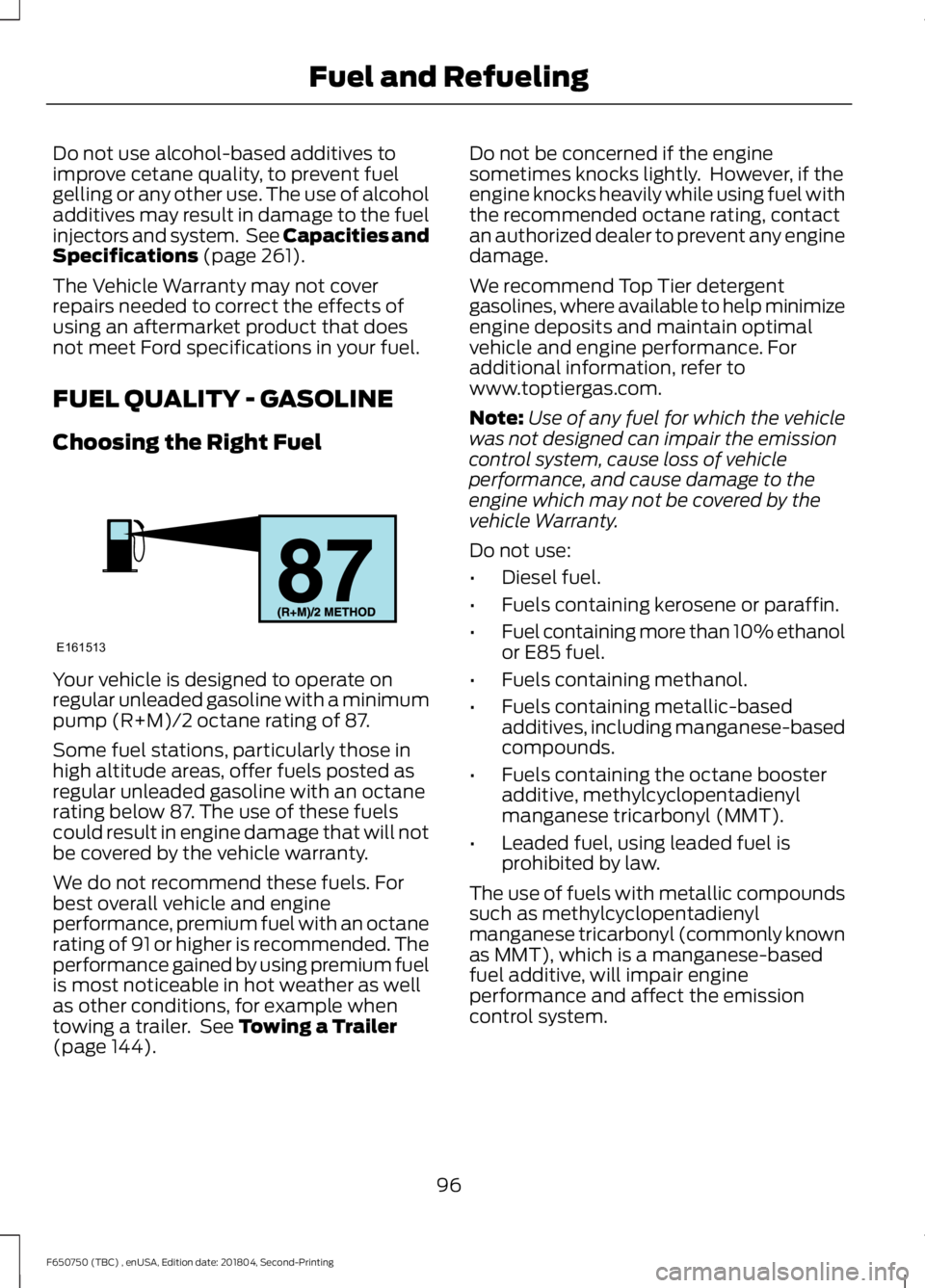
regular unleaded gasoline with a minimum
pump (R+M)/2 octane rating of 87.
Some fuel stations, particularly those in
high altitude areas, offer fuels posted as
regular unleaded gasoline with an octane
rating below 87. The use of these fuels
could result in engine damage that will not
be covered by the vehicle warranty.
We do not recommend these fuels. For
best overall vehicle and engine
performance, premium fuel with an octane
rating of 91 or higher is recommended. The
performance gained by using premium fuel
is most noticeable in hot weather as well
as other conditions, for example when
towing a trailer. See
Towing a Trailer
(page 144). Do not be concerned if the engine
sometimes knocks lightly. However, if the
engine knocks heavily while using fuel with
the recommended octane rating, contact
an authorized dealer to prevent any engine
damage.
We recommend Top Tier detergent
gasolines, where available to help minimize
engine deposits and maintain optimal
vehicle and engine performance. For
additional information, refer to
www.toptiergas.com.
Note:
Use of any fuel for which the vehicle
was not designed can impair the emission
control system, cause loss of vehicle
performance, and cause damage to the
engine which may not be covered by the
vehicle Warranty.
Do not use:
• Diesel fuel.
• Fuels containing kerosene or paraffin.
• Fuel containing more than 10% ethanol
or E85 fuel.
• Fuels containing methanol.
• Fuels containing metallic-based
additives, including manganese-based
compounds.
• Fuels containing the octane booster
additive, methylcyclopentadienyl
manganese tricarbonyl (MMT).
• Leaded fuel, using leaded fuel is
prohibited by law.
The use of fuels with metallic compounds
such as methylcyclopentadienyl
manganese tricarbonyl (commonly known
as MMT), which is a manganese-based
fuel additive, will impair engine
performance and affect the emission
control system.
96
F650750 (TBC) , enUSA, Edition date: 201804, Second-Printing Fuel and RefuelingE161513
Page 103 of 387
If the fuel cap warning lamp remains on,
at the next opportunity, safely pull off of
the road, remove the fuel filler cap, align
the cap properly and reinstall it. The check
fuel cap warning lamp or warning message
may not reset immediately. It may take
several driving cycles for the indicators to
turn off. A driving cycle consists of an
engine start-up (after four or more hours
with the engine off) followed by normal
city and highway driving.
FUEL CONSUMPTION
Real world fuel consumption is governed
by many factors, for example driving style,
high speed driving, stop-start driving, air
conditioning usage, the accessories fitted,
payload and towing.
•
The usable capacity of the fuel tank is
the amount of fuel that can be added
into the tank after the gauge indicates
empty.
• The advertised capacity is the total fuel
tank size. See Capacities and
Specifications (page 255). It is the
combined usable capacity plus the
empty reserve.
• Due to the empty reserve, you may not
be able to refuel the full amount of the
advertised capacity of the fuel tank
even when the fuel gauge reads empty.
Empty reserve is the amount of fuel
remaining in the tank after the fuel gauge
indicates empty. The amount of usable
fuel in the empty reserve varies and should
not be relied upon to increase driving range.
Filling the Tank
For consistent results when filling the fuel
tank: •
Turn the ignition off before refueling
your vehicle; a temporary inaccurate
reading may result if the engine is left
on when refueling your vehicle.
• Use the same fill rate
(low-medium-high) each time the tank
is refueled.
• Allow no more than two automatic
click-offs when refueling your vehicle.
Results are most accurate when the filling
method is consistent.
Calculating Fuel Economy
Do not measure fuel economy during the
first
900 mi (1,500 km) of driving (this is
your engine ’s break-in period); a more
accurate measurement is obtained after
1,900 mi (3,000 km)
.
Fuel expense, frequency of fill ups or fuel
gauge readings are not accurate ways to
measure fuel economy.
1. Fill the fuel tank completely and record
the initial odometer reading.
2. Each time you fill the fuel tank, record the amount of fuel added.
3. After at least three fill ups, fill the fuel tank and record the current odometer
reading.
4. Subtract your initial odometer reading from the current odometer reading.
5. Calculate fuel economy by dividing miles traveled by gallons used (For
Metric: Multiply liters used by 100, then
divide by kilometers traveled).
Keep a record for at least one month and
record the type of driving (city or highway).
This provides an accurate estimate of your
vehicle ’s fuel economy under current
driving conditions. Keeping records during
summer and winter will show how
temperature impacts fuel economy. In
general, your vehicle will use more fuel in
cold temperatures.
100
F650750 (TBC) , enUSA, Edition date: 201804, Second-Printing Fuel and Refueling
Page 104 of 387
Conditions That Affect Fuel Economy
•
Heavily loading your vehicle or towing
a trailer may reduce fuel economy at
any speed.
• Carrying unnecessary weight in your
vehicle may reduce fuel economy.
• Adding certain accessories to your
vehicle such as bug deflectors, rollbars
or light bars, running boards and ski
racks may reduce fuel economy.
• Using fuel blended with alcohol may
lower fuel economy.
• Fuel economy may decrease with lower
temperatures.
• You will get better fuel economy when
driving on flat terrain than when driving
on hilly terrain.
• Transmissions give their best fuel
economy when operated in the top
cruise gear and with steady pressure
on the accelerator pedal.
• Close the windows for high-speed
driving. FUEL TANK SELECTOR
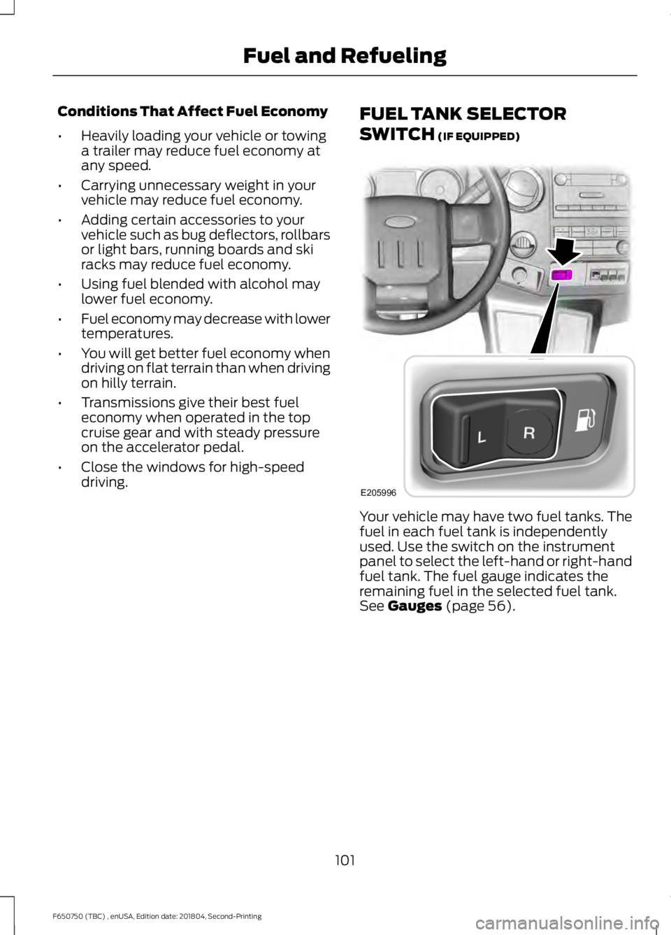
SWITCH (IF EQUIPPED) Your vehicle may have two fuel tanks. The
fuel in each fuel tank is independently
used. Use the switch on the instrument
panel to select the left-hand or right-hand
fuel tank. The fuel gauge indicates the
remaining fuel in the selected fuel tank.
See
Gauges (page 56).
101
F650750 (TBC) , enUSA, Edition date: 201804, Second-Printing Fuel and RefuelingE205996
Page 106 of 387
•
Incorrect fuel for climatic conditions.
• Incorrect engine oil viscosity for
climactic conditions.
Note: Some vehicles have a lifetime fuel
filter that is integrated with the fuel tank.
Regular maintenance or replacement is not
needed.
Note: If these checks do not help you
correct the concern, have your vehicle
checked as soon as possible.
Noise Emissions Warranty,
Prohibited Tampering Acts and
Maintenance
On January 1, 1978, Federal regulation
became effective governing the noise
emission on trucks over 10,000 lb
(4,536 kg) Gross Vehicle Weight Rating
(GVWR). The preceding statements
concerning prohibited tampering acts and
maintenance, and the noise warranty
found in the Warranty Guide, are
applicable to complete chassis cabs over
10,000 lb (4,536 kg)
GVWR.
CATALYTIC CONVERTER WARNING:
Do not park, idle or
drive your vehicle on dry grass or other
dry ground cover. The emission system
heats up the engine compartment and
exhaust system, creating the risk of fire. WARNING:
The normal operating
temperature of the exhaust system is
very high. Never work around or attempt
to repair any part of the exhaust system
until it has cooled. Use special care when
working around the catalytic converter.
The catalytic converter heats up to a very
high temperature after only a short
period of engine operation and stays hot
after the engine is switched off. WARNING:
Exhaust leaks may
result in entry of harmful and potentially
lethal fumes into the passenger
compartment. If you smell exhaust
fumes inside your vehicle, have your
vehicle inspected immediately. Do not
drive if you smell exhaust fumes.
Your vehicle has various emission control
components and a catalytic converter that
enables it to comply with applicable
exhaust emission standards.
To make sure that the catalytic converter
and other emission control components
continue to work properly:
• Do not crank the engine for more than
10 seconds at a time.
• Do not run the engine with a spark plug
lead disconnected.
• Do not push-start or tow-start your
vehicle. Use booster cables. See Jump
Starting the Vehicle
(page 156).
• Use only the specified fuel listed.
• Do not switch the ignition off when your
vehicle is moving.
• Avoid running out of fuel.
• Have the items listed in scheduled
maintenance information performed
according to the specified schedule.
Note: Resulting component damage may
not be covered by the vehicle Warranty.
The scheduled maintenance items listed
in scheduled maintenance information are
essential to the life and performance of
your vehicle and to its emissions system.
If you use anything other than Ford,
Motorcraft or Ford-authorized parts for
maintenance replacements or for service
of components affecting emission control,
such non-Ford parts should be equivalent
to genuine Ford Motor Company parts in
performance and durability.
103
F650750 (TBC) , enUSA, Edition date: 201804, Second-Printing Engine Emission Control
Page 119 of 387
•
Allows upshifts by moving gearshift
lever.
• Does not downshift into first (1) gear
at high speeds; allows for first (1) gear
when vehicle reaches slower speeds.
Forced downshifts
• Allowed in drive (D) with the tow/haul
feature on or off.
• Press the accelerator to the floor.
• Allows transmission to select an
appropriate gear.
Tow/Haul Mode To activate tow/haul, press the
button on the gearshift lever
once. The TOW HAUL indicator
light illuminates in the instrument cluster.
The tow/haul feature:
• Delays upshifts to reduce the frequency
of transmission shifting.
• Provides engine braking in all forward
gears, which slows your vehicle and
assists you in controlling your vehicle
when descending a grade.
• Depending on driving conditions and
load conditions, could downshift the
transmission to slow your vehicle and
help to control your vehicle speed
when descending a hill, without
pressing the accelerator pedal. Tapping
the brake pedal downshifts the
transmission to provide additional
braking, only if the downshift does not
cause an engine overspeed condition.
The tow/haul feature improves
transmission operation when towing a
trailer or a heavy load. All transmission
gear ranges are available when using
tow/haul. Note:
Under certain conditions, the
automatic tow/haul feature engages and
the TOW HAUL indicator comes on without
pressing the Tow/Haul button.
To deactivate the tow/haul feature and
return to normal driving mode, press the
button on the gearshift lever twice. The
TOW HAUL light deactivates. Tow/haul
also deactivates when you power down
your vehicle. WARNING: Do not use tow/haul
when the road surface is slippery. Failure
to follow this instruction could result in
the loss of control of your vehicle. WARNING:
Do not use diesel
engine exhaust braking when the road
surface is slippery. Failure to follow this
instruction could result in the loss of
control of your vehicle.
Understanding your SelectShift™
Automatic transmission
(If Equipped)
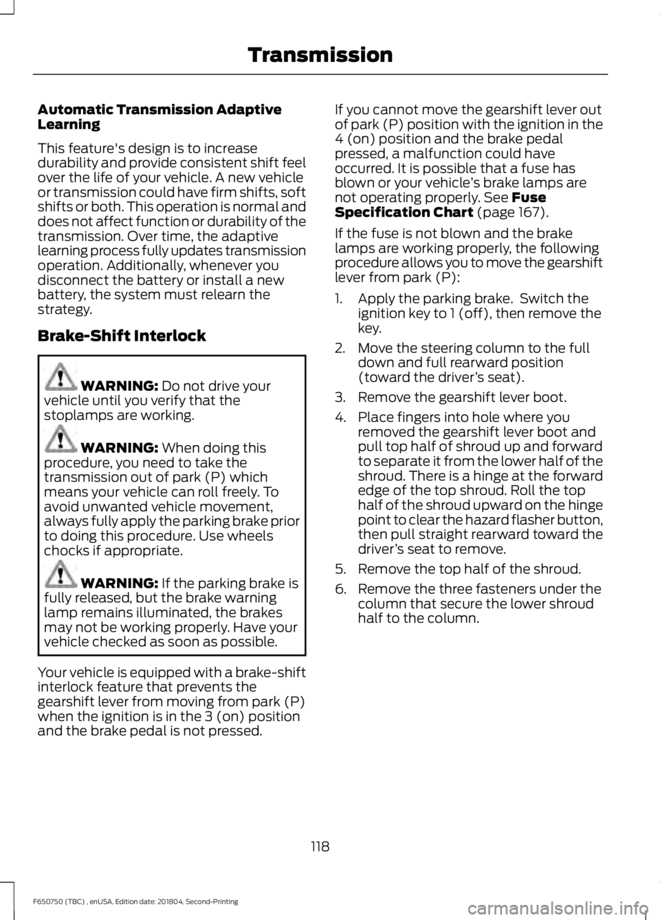
Your vehicle is equipped with a SelectShift
Automatic transmission gearshift lever.
SelectShift Automatic transmission gives
you the ability to change gears up or down
(without a clutch) as you prefer. 116
F650750 (TBC) , enUSA, Edition date: 201804, Second-Printing TransmissionE161509 E163184
Page 121 of 387
Automatic Transmission Adaptive
Learning
This feature's design is to increase
durability and provide consistent shift feel
over the life of your vehicle. A new vehicle
or transmission could have firm shifts, soft
shifts or both. This operation is normal and
does not affect function or durability of the
transmission. Over time, the adaptive
learning process fully updates transmission
operation. Additionally, whenever you
disconnect the battery or install a new
battery, the system must relearn the
strategy.
Brake-Shift Interlock
WARNING: Do not drive your
vehicle until you verify that the
stoplamps are working. WARNING:
When doing this
procedure, you need to take the
transmission out of park (P) which
means your vehicle can roll freely. To
avoid unwanted vehicle movement,
always fully apply the parking brake prior
to doing this procedure. Use wheels
chocks if appropriate. WARNING:
If the parking brake is
fully released, but the brake warning
lamp remains illuminated, the brakes
may not be working properly. Have your
vehicle checked as soon as possible.
Your vehicle is equipped with a brake-shift
interlock feature that prevents the
gearshift lever from moving from park (P)
when the ignition is in the 3 (on) position
and the brake pedal is not pressed. If you cannot move the gearshift lever out
of park (P) position with the ignition in the
4 (on) position and the brake pedal
pressed, a malfunction could have
occurred. It is possible that a fuse has
blown or your vehicle
’s brake lamps are
not operating properly.
See Fuse
Specification Chart (page 167).
If the fuse is not blown and the brake
lamps are working properly, the following
procedure allows you to move the gearshift
lever from park (P):
1. Apply the parking brake. Switch the ignition key to 1 (off), then remove the
key.
2. Move the steering column to the full down and full rearward position
(toward the driver ’s seat).
3. Remove the gearshift lever boot.
4. Place fingers into hole where you removed the gearshift lever boot and
pull top half of shroud up and forward
to separate it from the lower half of the
shroud. There is a hinge at the forward
edge of the top shroud. Roll the top
half of the shroud upward on the hinge
point to clear the hazard flasher button,
then pull straight rearward toward the
driver ’s seat to remove.
5. Remove the top half of the shroud.
6. Remove the three fasteners under the column that secure the lower shroud
half to the column.
118
F650750 (TBC) , enUSA, Edition date: 201804, Second-Printing Transmission
Page 122 of 387
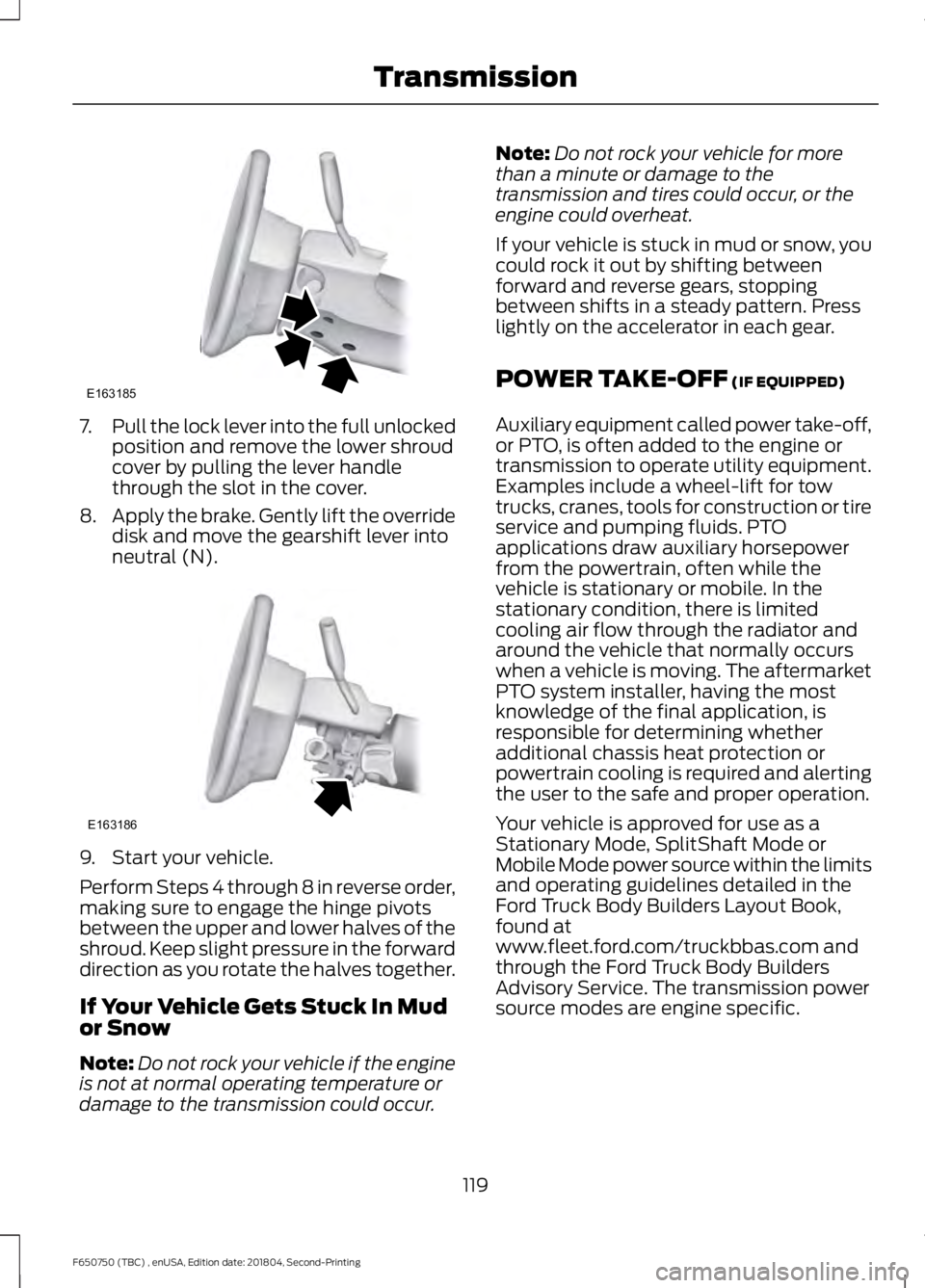
7.
Pull the lock lever into the full unlocked
position and remove the lower shroud
cover by pulling the lever handle
through the slot in the cover.
8. Apply the brake. Gently lift the override
disk and move the gearshift lever into
neutral (N). 9. Start your vehicle.
Perform Steps 4 through 8 in reverse order,
making sure to engage the hinge pivots
between the upper and lower halves of the
shroud. Keep slight pressure in the forward
direction as you rotate the halves together.
If Your Vehicle Gets Stuck In Mud
or Snow
Note:
Do not rock your vehicle if the engine
is not at normal operating temperature or
damage to the transmission could occur. Note:
Do not rock your vehicle for more
than a minute or damage to the
transmission and tires could occur, or the
engine could overheat.
If your vehicle is stuck in mud or snow, you
could rock it out by shifting between
forward and reverse gears, stopping
between shifts in a steady pattern. Press
lightly on the accelerator in each gear.
POWER TAKE-OFF (IF EQUIPPED)
Auxiliary equipment called power take-off,
or PTO, is often added to the engine or
transmission to operate utility equipment.
Examples include a wheel-lift for tow
trucks, cranes, tools for construction or tire
service and pumping fluids. PTO
applications draw auxiliary horsepower
from the powertrain, often while the
vehicle is stationary or mobile. In the
stationary condition, there is limited
cooling air flow through the radiator and
around the vehicle that normally occurs
when a vehicle is moving. The aftermarket
PTO system installer, having the most
knowledge of the final application, is
responsible for determining whether
additional chassis heat protection or
powertrain cooling is required and alerting
the user to the safe and proper operation.
Your vehicle is approved for use as a
Stationary Mode, SplitShaft Mode or
Mobile Mode power source within the limits
and operating guidelines detailed in the
Ford Truck Body Builders Layout Book,
found at
www.fleet.ford.com/truckbbas.com and
through the Ford Truck Body Builders
Advisory Service. The transmission power
source modes are engine specific.
119
F650750 (TBC) , enUSA, Edition date: 201804, Second-Printing TransmissionE163185 E163186
Page 125 of 387
GENERAL INFORMATION
WARNING: Do not apply the brake
pedal and accelerator pedal
simultaneously. Applying both pedals
simultaneously for more than a few
seconds will limit engine performance,
which may result in difficulty maintaining
speed in traffic and could lead to serious
injury.
Note: Occasional brake noise is normal. If
a metal-to-metal, continuous grinding or
continuous squeal sound is present, the
brake linings may be worn-out. Have the
system checked as soon as possible. If your
vehicle has continuous vibration or shudder
in the steering wheel while braking, have it
checked by an authorized dealer.
All standard equipment brakes are
self-adjusting. Automatic adjustment,
when required, occurs whenever you apply
and release the brakes during forward or
reverse operation.
Know the required stopping distances for
all driving conditions you may encounter.
For longer brake lining life, take full
advantage of engine braking power when
coming to a stop.
Wet brakes result in reduced braking
efficiency. Gently press the brake pedal a
few times when driving from a car wash or
standing water to dry the brakes.
If the brakes do not grip well:
• Check brake adjustment.
• Check the brake linings for excessive
wear.
• Check the system air pressure on
vehicles with air brakes. •
Let the brakes cool if you have been
using them excessively, as in mountain
driving or after several fast, high-speed
stops.
• If you have been driving through deep
water, gently apply the brakes several
times while your vehicle is moving
slowly.
Brake Over Accelerator
In the event the accelerator pedal
becomes stuck or entrapped, apply steady
and firm pressure to the brake pedal to
slow the vehicle and reduce engine power.
If you experience this condition, apply the
brakes and bring your vehicle to a safe
stop. Move the transmission to park (P),
switch the engine off and apply the parking
brake. Inspect the accelerator pedal for
any interference. If none are found and the
condition persists, have your vehicle towed
to the nearest authorized dealer
Anti-lock Brake System
This system helps you maintain steering
control during emergency stops by keeping
the brakes from locking. This lamp momentarily
illuminates when you switch the
ignition on. If the light does not
illuminate during start up, remains on or
flashes, the system may be disabled. Have
the system checked by an authorized
dealer. If you connect a PLC trailer with
the ignition on, the trailer ABS
light also illuminates. If the light
fails to illuminate, if it remains on after you
start the vehicle or continues to flash, have
the system serviced immediately.
See
Warning Lamps and Indicators
(page 60).
122
F650750 (TBC) , enUSA, Edition date: 201804, Second-Printing Brakes E210335
Page 128 of 387
Releasing the Parking Brake
WARNING: When your vehicle is
stationary, keep the brake pedal fully
pressed when shifting gears. Failure to
follow this instruction could result in
personal injury, death or property
damage.
Note: Read and understand the following
steps and perform them whenever you
prepare to drive the vehicle.
Note: The parking brake does not disengage
unless sufficient system air pressure is
available.
1. Press and hold the service brake pedal
while the engine is running.
2. Select the appropriate drive gear.
3. Push and hold the yellow dash-mounted parking brake knob until
the parking brake light turns off, then
release.
Parking Brake Light Illumination Due
to Low Air Pressure
If the air pressure becomes too low at any
time during vehicle operation, the parking
brake may apply and the parking brake
light turns on.
If the parking brake applies due to low air
pressure, immediate service is required to
the parking brake system.
Releasing Spring Brake with Air
Pressure
The air system in all vehicles with
spring-actuated rear wheel parking brakes
has a valve on the governor for connection
to an outside air supply. The valve lets you
recharge the system with air from an
outside source, releasing the
spring-actuated parking brakes. Your
vehicle is now ready to tow in an
emergency. You can only use an outside air source if
the protected system is in operating
condition. If you cannot restore air pressure
in the protected air system, you must
release the spring-actuated brakes
manually.
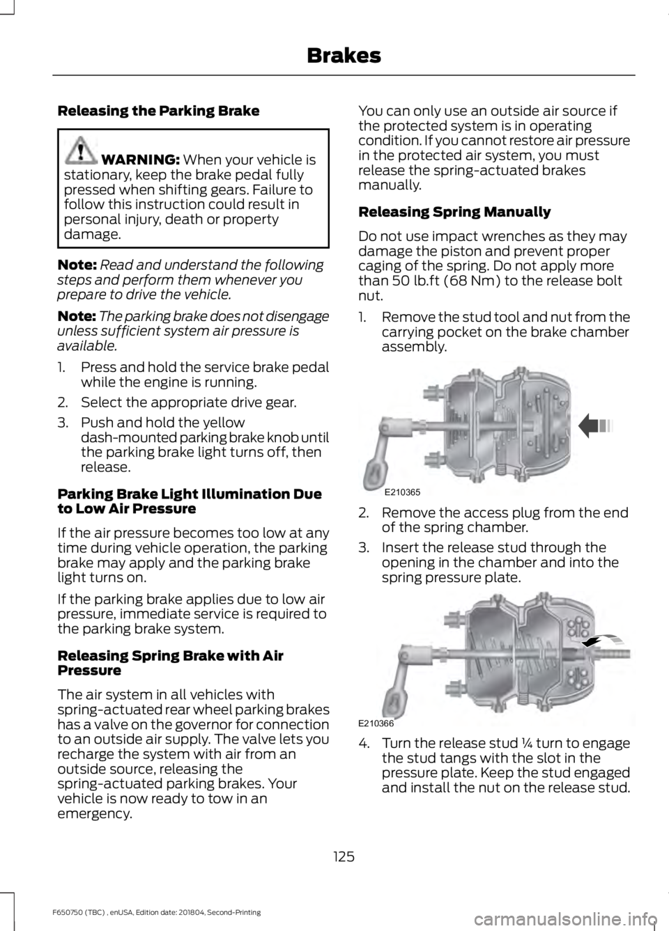
Releasing Spring Manually
Do not use impact wrenches as they may
damage the piston and prevent proper
caging of the spring. Do not apply more
than
50 lb.ft (68 Nm) to the release bolt
nut.
1. Remove the stud tool and nut from the
carrying pocket on the brake chamber
assembly. 2. Remove the access plug from the end
of the spring chamber.
3. Insert the release stud through the opening in the chamber and into the
spring pressure plate. 4.
Turn the release stud ¼ turn to engage
the stud tangs with the slot in the
pressure plate. Keep the stud engaged
and install the nut on the release stud.
125
F650750 (TBC) , enUSA, Edition date: 201804, Second-Printing BrakesE210365 E210366