transmission fluid FORD F650/750 2019 Owners Manual
[x] Cancel search | Manufacturer: FORD, Model Year: 2019, Model line: F650/750, Model: FORD F650/750 2019Pages: 387, PDF Size: 4.78 MB
Page 6 of 387
Using Traction Control - Vehicles With:
Hydraulic Brakes ......................................133
Stability Control
Principle of Operation ................................
135
Using Stability Control ..............................
136
Cruise Control
Principle of Operation ................................
138
Using Cruise Control ...................................
138
Driving Aids
Steering ...........................................................
140
Load Carrying
Load Limit ........................................................
141
Air Suspension ..............................................
142
Towing
Towing a Trailer ............................................
144
Recommended Towing Weights ...........
145
Essential Towing Checks ..........................
146
Fifth Wheel Operation ...............................
147
Driving Hints
Breaking-In ....................................................
149
General Driving Points ...............................
149
Economical Driving .....................................
150
Cold Weather Precautions ........................
151
Driving Through Water ...............................
153
Roadside Emergencies
Roadside Assistance ..................................
154
Hazard Flashers ............................................
155
Fuel Shutoff ...................................................
155
Jump Starting the Vehicle ........................
156
Transporting the Vehicle ..........................
158
Customer Assistance
Ford Credit .....................................................
160Getting the Services You Need
..............
160
In California (U.S. Only) .............................
161
The Better Business Bureau (BBB) Auto Line Program (U.S. Only) .....................
162
Utilizing the Mediation/Arbitration Program (Canada Only) .......................
163
Getting Assistance Outside the U.S. and Canada ........................................................
163
Ordering Additional Owner's Literature ........................................................................\
.
164
Reporting Safety Defects (U.S. Only) ........................................................................\
.
165
Reporting Safety Defects (Canada Only) ........................................................................\
.
165
Fuses
Fuse Specification Chart ...........................
167
Changing a Fuse ...........................................
176
Vehicle Inspection Guide
Vehicle Inspection Information ..............
178
Maintenance
General Information ...................................
187
Opening and Closing the Hood .............
188
Under Hood Overview - 6.7L Diesel ......
190
Under Hood Overview - 6.8L ...................
191
Engine Oil Dipstick - 6.7L Diesel .............
192
Engine Oil Dipstick - 6.8L .........................
192
Engine Oil Check - 6.7L Diesel ................
192
Engine Oil Check - 6.8L .............................
193
Changing the Engine Oil and Oil Filter ........................................................................\
.
194
Changing the Crankcase Vent Filter Element - 6.7L Diesel .............................
195
Oil Change Indicator Reset ......................
196
Engine Coolant Check - 6.7L Diesel ......
196
Engine Coolant Check - 6.8L .................
200
Automatic Transmission Fluid Check ........................................................................\
204
Brake Fluid Check .......................................
205
3
F650750 (TBC) , enUSA, Edition date: 201804, Second-Printing Table of Contents
Page 7 of 387
Power Steering Fluid Check
...................206
Washer Fluid Check ...................................
206
Draining the Fuel Filter Water Trap - 6.7L Diesel ...........................................................
207
Fuel Filter - 6.8L ..........................................
207
Changing the 12V Battery ........................
208
Checking the Wiper Blades .....................
210
Changing the Wiper Blades .....................
210
Adjusting the Headlamps ........................
210
Removing a Headlamp ..............................
212
Changing a Bulb ...........................................
212
Changing the Engine Air Filter - 6.7L Diesel ............................................................
213
Changing the Engine Air Filter - 6.8L ........................................................................\
.
216
Changing the Engine-Mounted and Diesel Fuel Conditioner Module Fuel
Filters ............................................................
218
Electrical System Inspection ...................
221
Air Induction System Inspection ............
221
Exhaust System Inspection ....................
222
Brake System Inspection .........................
222
Axle Inspection ............................................
225
Steering System Inspection ....................
226
Suspension System Inspection .............
227
Frame and Tow Hook Inspection ..........
227
Rear Axle Fluid Check ................................
227
Spring U-Bolt Check ..................................
228
Vehicle Care
General Information ..................................
229
Cleaning Products ......................................
229
Cleaning the Exterior .................................
229
Waxing .............................................................
231
Cleaning the Engine ....................................
231
Cleaning the Windows and Wiper Blades ........................................................................\
.
231
Cleaning the Interior ...................................
232
Cleaning the Instrument Panel and Instrument Cluster Lens .......................
232
Repairing Minor Paint Damage ..............
233Cleaning the Wheels
..................................
233
Vehicle Storage ............................................
234
Wheels and Tires
Tire Care .........................................................
236
Using Snow Chains .....................................
251
Changing a Road Wheel ...........................
251
Technical Specifications ..........................
253
Capacities and Specifications
Engine Specifications - 6.7L Diesel ......
255
Engine Specifications - 6.8L ..................
256
Motorcraft Parts - 6.7L Diesel .................
257
Motorcraft Parts - 6.8L .............................
258
Vehicle Identification Number ...............
259
Vehicle Certification Label ......................
260
Transmission Code Designation ...........
260
Capacities and Specifications - 6.7L Diesel ...........................................................
261
Capacities and Specifications - 6.8L ........................................................................\
269
Bulb Specification Chart ..........................
275
Audio System
General Information ...................................
277
Audio Unit - Vehicles With: AM/FM ......
278
Audio Unit - Vehicles With: AM/FM/CD/ SYNC ...........................................................
279
Satellite Radio .............................................
282
Audio Input Jack .........................................
284
USB Port ........................................................
285
Media Hub .....................................................
285
SYNC™
General Information ..................................
287
Using Voice Recognition ..........................
289
Using SYNC™ With Your Phone ............
291
Using SYNC™ With Your Media Player ........................................................................\
303
4
F650750 (TBC) , enUSA, Edition date: 201804, Second-Printing Table of Contents
Page 12 of 387
If these modified engine performance
characteristics persist for an extended
period and either the service engine soon
or powertrain malfunction, reduced power,
electronic throttle control light is
illuminated, have the system checked by
an authorized dealer.
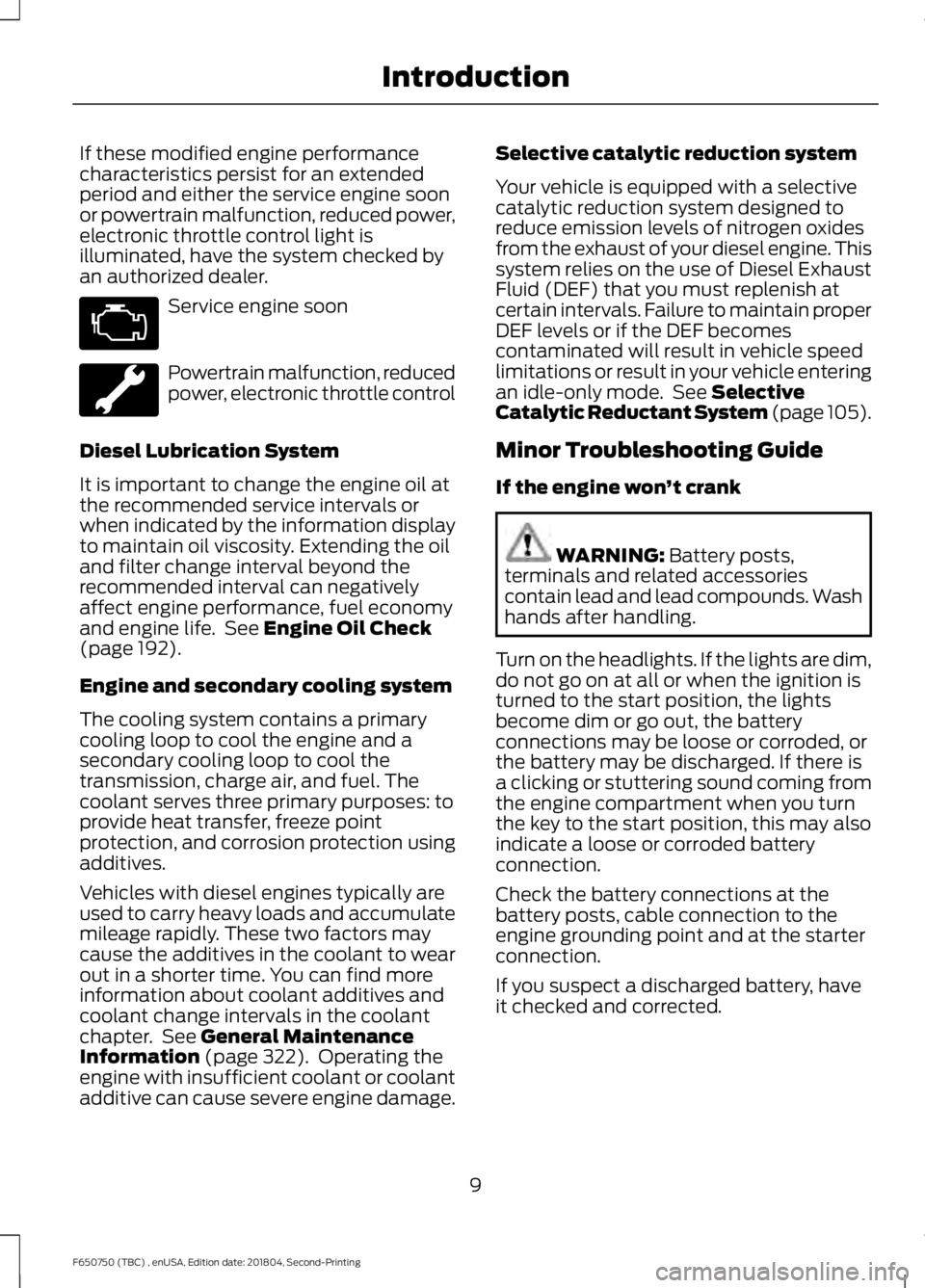
Service engine soon
Powertrain malfunction, reduced
power, electronic throttle control
Diesel Lubrication System
It is important to change the engine oil at
the recommended service intervals or
when indicated by the information display
to maintain oil viscosity. Extending the oil
and filter change interval beyond the
recommended interval can negatively
affect engine performance, fuel economy
and engine life. See Engine Oil Check
(page 192).
Engine and secondary cooling system
The cooling system contains a primary
cooling loop to cool the engine and a
secondary cooling loop to cool the
transmission, charge air, and fuel. The
coolant serves three primary purposes: to
provide heat transfer, freeze point
protection, and corrosion protection using
additives.
Vehicles with diesel engines typically are
used to carry heavy loads and accumulate
mileage rapidly. These two factors may
cause the additives in the coolant to wear
out in a shorter time. You can find more
information about coolant additives and
coolant change intervals in the coolant
chapter. See
General Maintenance
Information (page 322). Operating the
engine with insufficient coolant or coolant
additive can cause severe engine damage. Selective catalytic reduction system
Your vehicle is equipped with a selective
catalytic reduction system designed to
reduce emission levels of nitrogen oxides
from the exhaust of your diesel engine. This
system relies on the use of Diesel Exhaust
Fluid (DEF) that you must replenish at
certain intervals. Failure to maintain proper
DEF levels or if the DEF becomes
contaminated will result in vehicle speed
limitations or result in your vehicle entering
an idle-only mode. See
Selective
Catalytic Reductant System (page 105).
Minor Troubleshooting Guide
If the engine won ’t crank WARNING:
Battery posts,
terminals and related accessories
contain lead and lead compounds. Wash
hands after handling.
Turn on the headlights. If the lights are dim,
do not go on at all or when the ignition is
turned to the start position, the lights
become dim or go out, the battery
connections may be loose or corroded, or
the battery may be discharged. If there is
a clicking or stuttering sound coming from
the engine compartment when you turn
the key to the start position, this may also
indicate a loose or corroded battery
connection.
Check the battery connections at the
battery posts, cable connection to the
engine grounding point and at the starter
connection.
If you suspect a discharged battery, have
it checked and corrected.
9
F650750 (TBC) , enUSA, Edition date: 201804, Second-Printing Introduction
Page 59 of 387
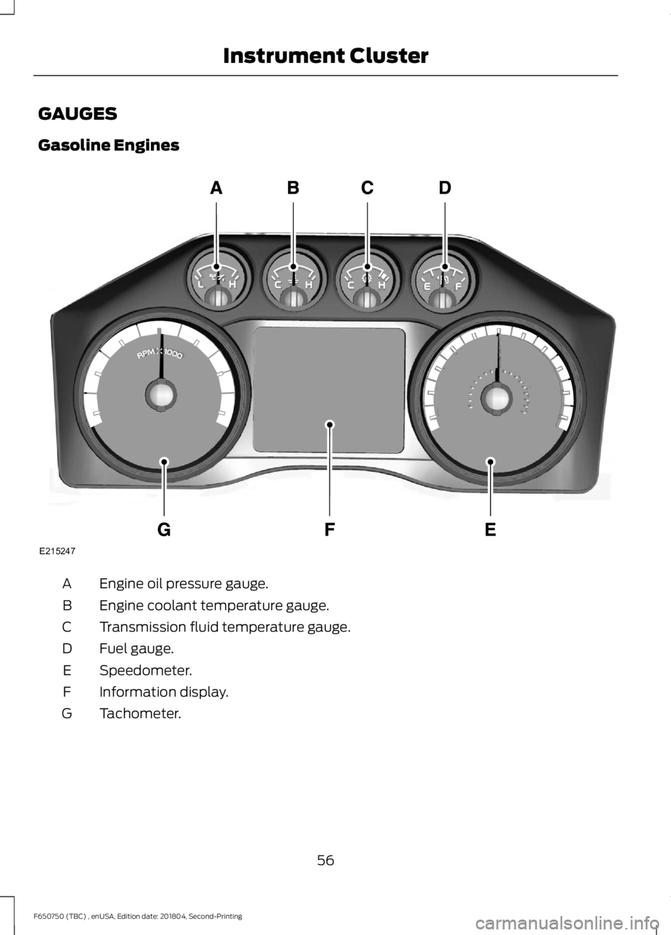
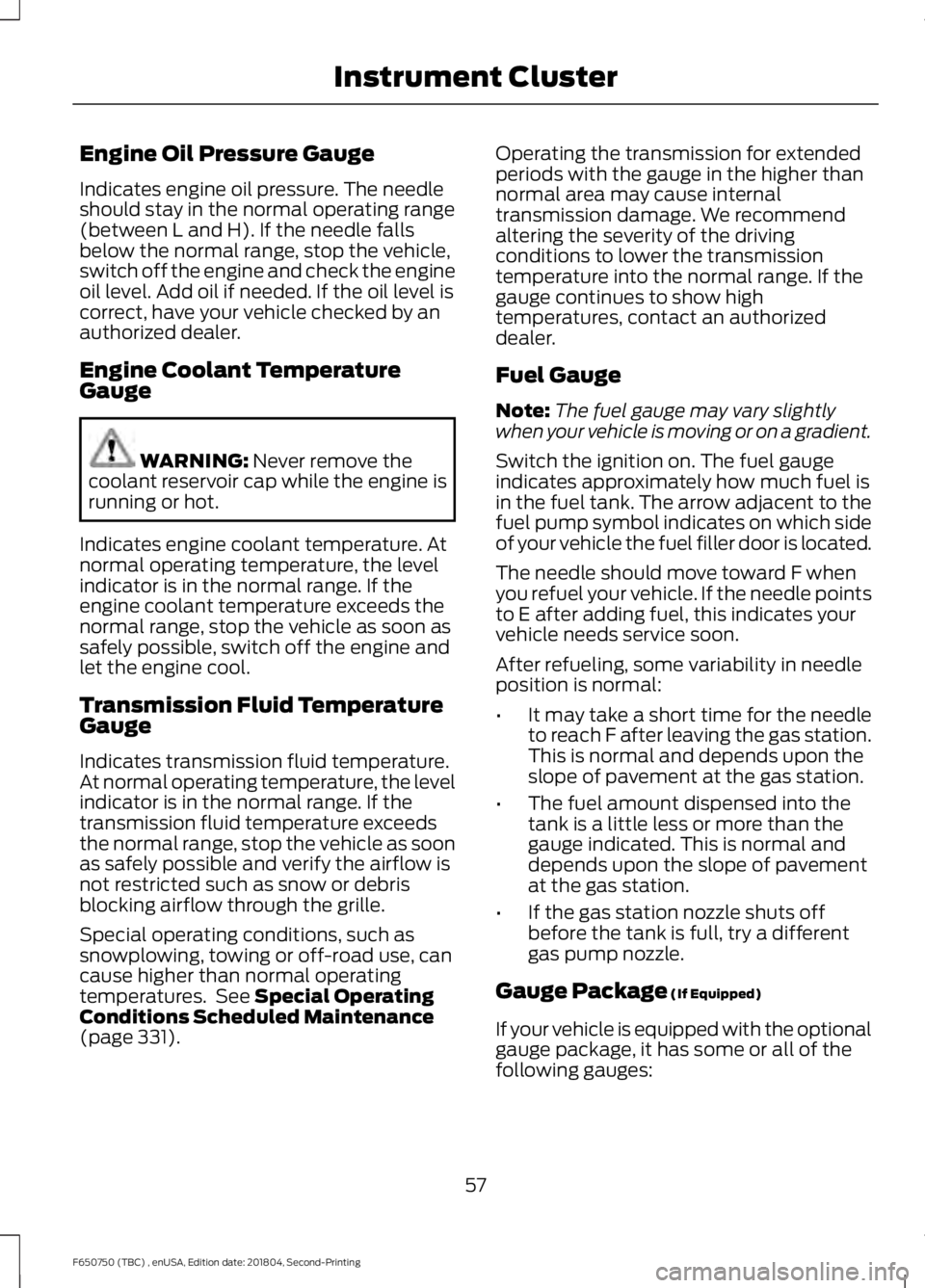
GAUGES
Gasoline Engines
Engine oil pressure gauge.
A
Engine coolant temperature gauge.
B
Transmission fluid temperature gauge.
C
Fuel gauge.
D
Speedometer.
E
Information display.
F
Tachometer.
G
56
F650750 (TBC) , enUSA, Edition date: 201804, Second-Printing Instrument ClusterE215247
Page 60 of 387
Engine Oil Pressure Gauge
Indicates engine oil pressure. The needle
should stay in the normal operating range
(between L and H). If the needle falls
below the normal range, stop the vehicle,
switch off the engine and check the engine
oil level. Add oil if needed. If the oil level is
correct, have your vehicle checked by an
authorized dealer.
Engine Coolant Temperature
Gauge
WARNING: Never remove the
coolant reservoir cap while the engine is
running or hot.
Indicates engine coolant temperature. At
normal operating temperature, the level
indicator is in the normal range. If the
engine coolant temperature exceeds the
normal range, stop the vehicle as soon as
safely possible, switch off the engine and
let the engine cool.
Transmission Fluid Temperature
Gauge
Indicates transmission fluid temperature.
At normal operating temperature, the level
indicator is in the normal range. If the
transmission fluid temperature exceeds
the normal range, stop the vehicle as soon
as safely possible and verify the airflow is
not restricted such as snow or debris
blocking airflow through the grille.
Special operating conditions, such as
snowplowing, towing or off-road use, can
cause higher than normal operating
temperatures. See
Special Operating
Conditions Scheduled Maintenance
(page
331). Operating the transmission for extended
periods with the gauge in the higher than
normal area may cause internal
transmission damage. We recommend
altering the severity of the driving
conditions to lower the transmission
temperature into the normal range. If the
gauge continues to show high
temperatures, contact an authorized
dealer.
Fuel Gauge
Note:
The fuel gauge may vary slightly
when your vehicle is moving or on a gradient.
Switch the ignition on. The fuel gauge
indicates approximately how much fuel is
in the fuel tank. The arrow adjacent to the
fuel pump symbol indicates on which side
of your vehicle the fuel filler door is located.
The needle should move toward F when
you refuel your vehicle. If the needle points
to E after adding fuel, this indicates your
vehicle needs service soon.
After refueling, some variability in needle
position is normal:
• It may take a short time for the needle
to reach F after leaving the gas station.
This is normal and depends upon the
slope of pavement at the gas station.
• The fuel amount dispensed into the
tank is a little less or more than the
gauge indicated. This is normal and
depends upon the slope of pavement
at the gas station.
• If the gas station nozzle shuts off
before the tank is full, try a different
gas pump nozzle.
Gauge Package
(If Equipped)
If your vehicle is equipped with the optional
gauge package, it has some or all of the
following gauges:
57
F650750 (TBC) , enUSA, Edition date: 201804, Second-Printing Instrument Cluster
Page 61 of 387
•
Transmission temperature gauge:
Displays the transmission fluid
temperature at the transmission sump.
• Hourmeter: Displays the hours of
engine run time.
• Voltmeter:
Displays electrical system
voltage. Information Display
Odometer
Located in the bottom of the information
display. Registers the accumulated
distance your vehicle has traveled.
Trip Computer
See
General Information (page 64).
Vehicle Settings and Personalization
See
General Information (page 64).
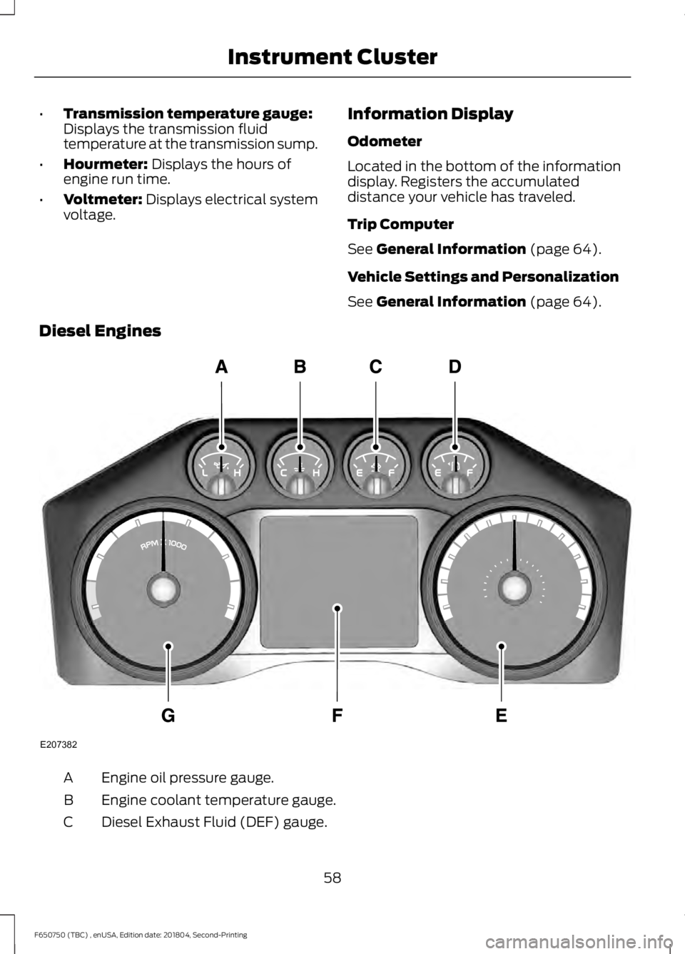
Diesel Engines Engine oil pressure gauge.
A
Engine coolant temperature gauge.
B
Diesel Exhaust Fluid (DEF) gauge.
C
58
F650750 (TBC) , enUSA, Edition date: 201804, Second-Printing Instrument ClusterE207382
Page 62 of 387
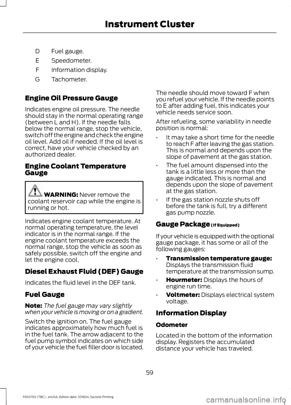
Fuel gauge.
D
Speedometer.
E
Information display.
F
Tachometer.
G
Engine Oil Pressure Gauge
Indicates engine oil pressure. The needle
should stay in the normal operating range
(between L and H). If the needle falls
below the normal range, stop the vehicle,
switch off the engine and check the engine
oil level. Add oil if needed. If the oil level is
correct, have your vehicle checked by an
authorized dealer.
Engine Coolant Temperature
Gauge WARNING: Never remove the
coolant reservoir cap while the engine is
running or hot.
Indicates engine coolant temperature. At
normal operating temperature, the level
indicator is in the normal range. If the
engine coolant temperature exceeds the
normal range, stop the vehicle as soon as
safely possible, switch off the engine and
let the engine cool.
Diesel Exhaust Fluid (DEF) Gauge
Indicates the fluid level in the DEF tank.
Fuel Gauge
Note: The fuel gauge may vary slightly
when your vehicle is moving or on a gradient.
Switch the ignition on. The fuel gauge
indicates approximately how much fuel is
in the fuel tank. The arrow adjacent to the
fuel pump symbol indicates on which side
of your vehicle the fuel filler door is located. The needle should move toward F when
you refuel your vehicle. If the needle points
to E after adding fuel, this indicates your
vehicle needs service soon.
After refueling, some variability in needle
position is normal:
•
It may take a short time for the needle
to reach F after leaving the gas station.
This is normal and depends upon the
slope of pavement at the gas station.
• The fuel amount dispensed into the
tank is a little less or more than the
gauge indicated. This is normal and
depends upon the slope of pavement
at the gas station.
• If the gas station nozzle shuts off
before the tank is full, try a different
gas pump nozzle.
Gauge Package
(If Equipped)
If your vehicle is equipped with the optional
gauge package, it has some or all of the
following gauges:
• Transmission temperature gauge:
Displays the transmission fluid
temperature at the transmission sump.
• Hourmeter:
Displays the hours of
engine run time.
• Voltmeter:
Displays electrical system
voltage.
Information Display
Odometer
Located in the bottom of the information
display. Registers the accumulated
distance your vehicle has traveled.
59
F650750 (TBC) , enUSA, Edition date: 201804, Second-Printing Instrument Cluster
Page 107 of 387
Illumination of the service engine soon
indicator, charging system warning light or
the temperature warning light, fluid leaks,
strange odors, smoke or loss of engine
power could indicate that the emission
control system is not working properly.
An improperly operating or damaged
exhaust system may allow exhaust to
enter the vehicle. Have a damaged or
improperly operating exhaust system
inspected and repaired immediately.
Do not make any unauthorized changes to
your vehicle or engine. By law, vehicle
owners and anyone who manufactures,
repairs, services, sells, leases, trades
vehicles, or supervises a fleet of vehicles
are not permitted to intentionally remove
an emission control device or prevent it
from working. Information about your
vehicle
’s emission system is on the Vehicle
Emission Control Information Decal
located on or near the engine. This decal
also lists engine displacement.
Please consult your warranty information
for complete details.
On-Board Diagnostics (OBD-II)
Your vehicle has a computer known as the
on-board diagnostics system (OBD-II) that
monitors the engine ’s emission control
system. The system protects the
environment by making sure that your
vehicle continues to meet government
emission standards. The OBD-II system
also assists a service technician in properly
servicing your vehicle. When the service engine soon
indicator illuminates, the OBD-II
system has detected a
malfunction. Temporary malfunctions may
cause the service engine soon indicator to
illuminate. Examples are: 1. Your vehicle has run out of fuel
—the
engine may misfire or run poorly.
2. Poor fuel quality or water in the fuel —the engine may misfire or run
poorly.
3. The fuel fill inlet may not have closed properly. See Refueling (page 97).
4. Driving through deep water —the
electrical system may be wet.
You can correct these temporary
malfunctions by filling the fuel tank with
good quality fuel, properly closing the fuel
fill inlet or letting the electrical system dry
out. After three driving cycles without these
or any other temporary malfunctions
present, the service engine soon indicator
should stay off the next time you start the
engine. A driving cycle consists of a cold
engine startup followed by mixed city and
highway driving. No additional vehicle
service is required.
If the service engine soon indicator remains
on, have your vehicle serviced at the first
available opportunity. Although some
malfunctions detected by the OBD-II may
not have symptoms that are apparent,
continued driving with the service engine
soon indicator on can result in increased
emissions, lower fuel economy, reduced
engine and transmission smoothness and
lead to more costly repairs.
Readiness for Inspection and
Maintenance (I/M) Testing
Some state and provincial and local
governments may have
Inspection/Maintenance (I/M) programs
to inspect the emission control equipment
on your vehicle. Failure to pass this
inspection could prevent you from getting
a vehicle registration. If the service engine soon
indicator is on or the bulb does
not work, your vehicle may need
service. See On-Board Diagnostics.
104
F650750 (TBC) , enUSA, Edition date: 201804, Second-Printing Engine Emission Control
Page 108 of 387
Your vehicle may not pass the I/M test if
the service engine soon indicator is on or
not working properly (bulb is burned out),
or if the OBD-II system has determined
that some of the emission control systems
have not been properly checked. In this
case, the vehicle is not ready for I/M
testing.
If the vehicle
’s engine or transmission has
just been serviced, or the battery has
recently run down or been replaced, the
OBD-II system may indicate that the
vehicle is not ready for I/M testing. To
determine if the vehicle is ready for I/M
testing, turn the ignition key to the on
position for 15 seconds without cranking
the engine. If the service engine soon
indicator blinks eight times, it means that
the vehicle is not ready for I/M testing; if
the service engine soon indicator stays on
solid, it means that your vehicle is ready
for I/M testing.
The OBD-II system checks the emission
control system during normal driving. A
complete check may take several days.
If the vehicle is not ready for I/M testing,
you can perform the following driving cycle
consisting of mixed city and highway
driving:
1. 15 minutes of steady driving on an expressway or highway followed by 20
minutes of stop-and-go driving with at
least four 30-second idle periods.
2. Allow your vehicle to sit for at least eight hours with the ignition off. Then,
start the vehicle and complete the
above driving cycle. The vehicle must
warm up to its normal operating
temperature. Once started, do not turn
off the vehicle until the above driving
cycle is complete.
If the vehicle is still not ready for I/M
testing, you need to repeat the above
driving cycle. SELECTIVE CATALYTIC
REDUCTANT SYSTEM - DIESEL
Your vehicle may have a selective catalytic
reduction system. The system helps reduce
emission levels of oxides of nitrogen from
the exhaust system. The system
automatically injects diesel exhaust fluid
into the exhaust system to enable correct
selective catalytic reduction system
function.
Note:
Selective catalytic reduction systems
are not fitted to vehicles in markets where
only high-sulfur diesel fuel is available.
Diesel Exhaust Fluid Level
In order for the system to operate correctly
you must maintain the diesel exhaust fluid
level.
A warning message appears in the
information display when the diesel
exhaust fluid level is low. If a warning
message appears, refill the diesel exhaust
fluid tank as soon as possible. See
Information Messages (page 67).
Filling the Diesel Exhaust Fluid
Tank WARNING:
Keep diesel exhaust
fluid out of reach of children. Avoid
contact with skin, eyes or clothing. In
case of contact with your eyes, flush
immediately with water and get prompt
medical attention. In case of contact
with your skin, clean immediately with
soap and water. If you swallow any
diesel exhaust fluid, drink plenty of
water, call a physician immediately.
105
F650750 (TBC) , enUSA, Edition date: 201804, Second-Printing Engine Emission Control
Page 122 of 387
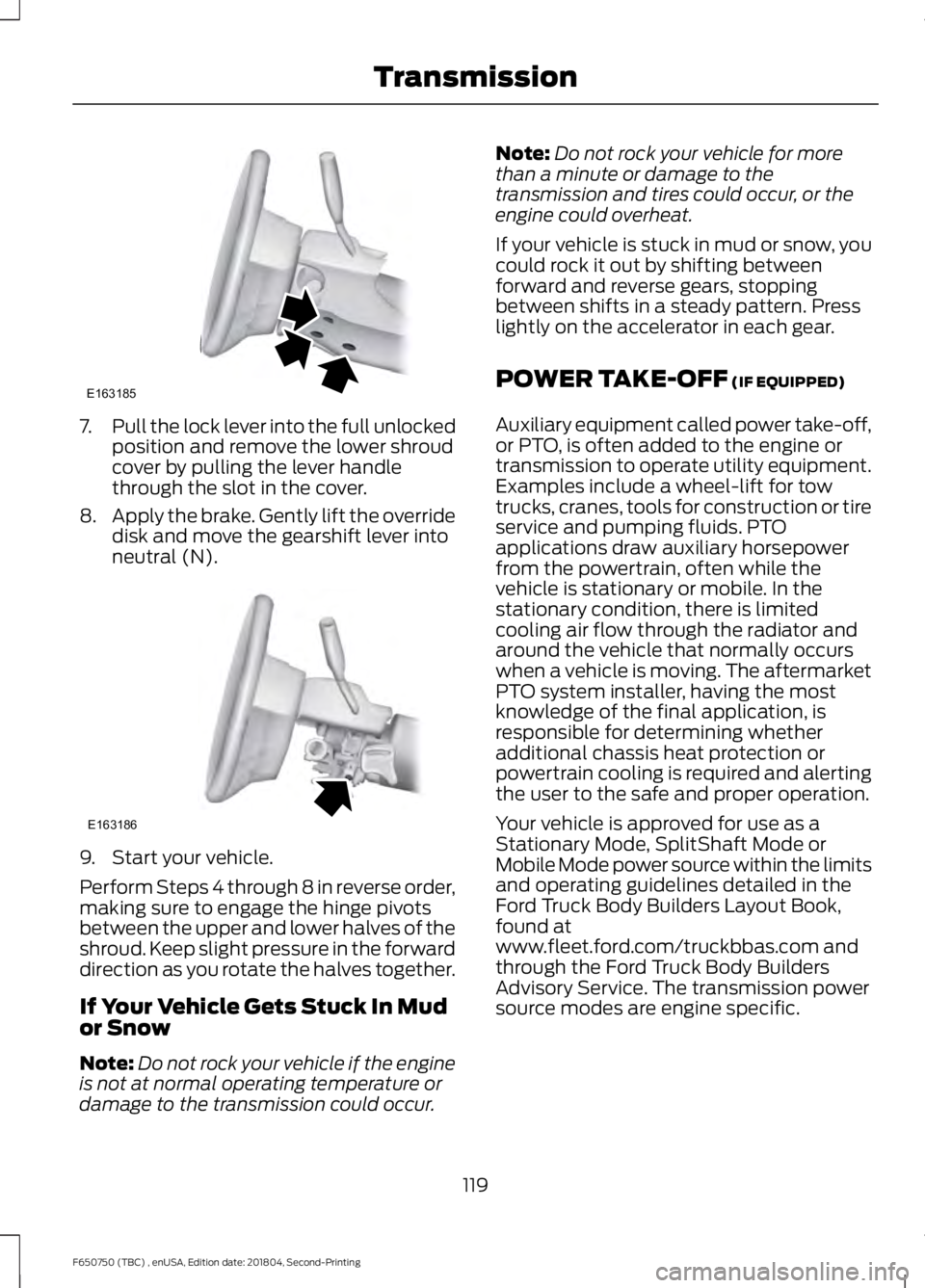
7.
Pull the lock lever into the full unlocked
position and remove the lower shroud
cover by pulling the lever handle
through the slot in the cover.
8. Apply the brake. Gently lift the override
disk and move the gearshift lever into
neutral (N). 9. Start your vehicle.
Perform Steps 4 through 8 in reverse order,
making sure to engage the hinge pivots
between the upper and lower halves of the
shroud. Keep slight pressure in the forward
direction as you rotate the halves together.
If Your Vehicle Gets Stuck In Mud
or Snow
Note:
Do not rock your vehicle if the engine
is not at normal operating temperature or
damage to the transmission could occur. Note:
Do not rock your vehicle for more
than a minute or damage to the
transmission and tires could occur, or the
engine could overheat.
If your vehicle is stuck in mud or snow, you
could rock it out by shifting between
forward and reverse gears, stopping
between shifts in a steady pattern. Press
lightly on the accelerator in each gear.
POWER TAKE-OFF (IF EQUIPPED)
Auxiliary equipment called power take-off,
or PTO, is often added to the engine or
transmission to operate utility equipment.
Examples include a wheel-lift for tow
trucks, cranes, tools for construction or tire
service and pumping fluids. PTO
applications draw auxiliary horsepower
from the powertrain, often while the
vehicle is stationary or mobile. In the
stationary condition, there is limited
cooling air flow through the radiator and
around the vehicle that normally occurs
when a vehicle is moving. The aftermarket
PTO system installer, having the most
knowledge of the final application, is
responsible for determining whether
additional chassis heat protection or
powertrain cooling is required and alerting
the user to the safe and proper operation.
Your vehicle is approved for use as a
Stationary Mode, SplitShaft Mode or
Mobile Mode power source within the limits
and operating guidelines detailed in the
Ford Truck Body Builders Layout Book,
found at
www.fleet.ford.com/truckbbas.com and
through the Ford Truck Body Builders
Advisory Service. The transmission power
source modes are engine specific.
119
F650750 (TBC) , enUSA, Edition date: 201804, Second-Printing TransmissionE163185 E163186