fuel FORD F650/750 2023 Repair Manual
[x] Cancel search | Manufacturer: FORD, Model Year: 2023, Model line: F650/750, Model: FORD F650/750 2023Pages: 378, PDF Size: 5.65 MB
Page 218 of 378
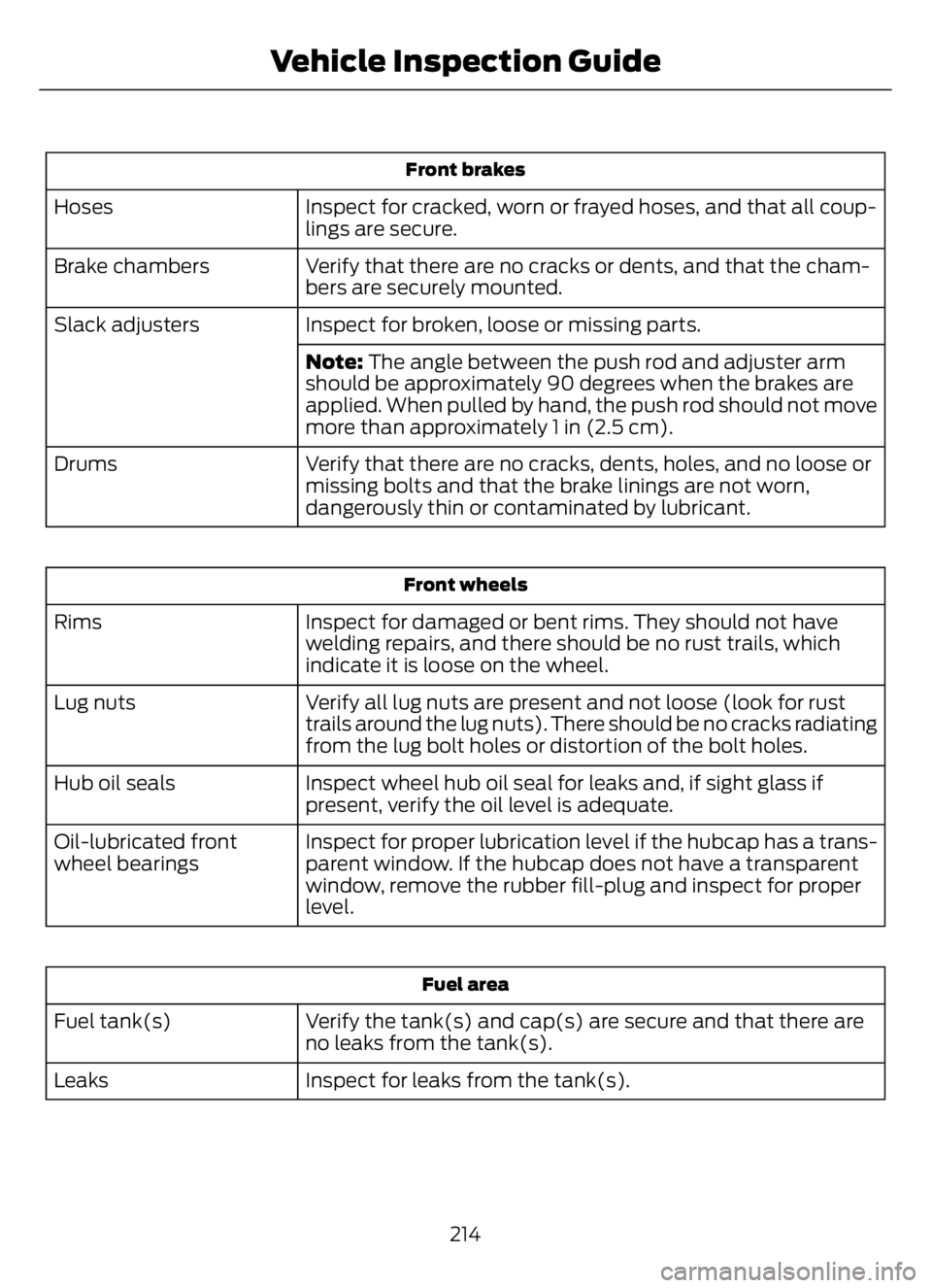
Front brakes
Inspect for cracked, worn or frayed hoses, and that all coup-
lings are secure. Hoses
Verify that there are no cracks or dents, and that the cham-
bers are securely mounted. Brake chambers
Inspect for broken, loose or missing parts. Slack adjusters
Note: The angle between the push rod and adjuster arm
should be approximately 90 degrees when the brakes are
applied. When pulled by hand, the push rod should not move
more than approximately 1 in (2.5 cm).
Verify that there are no cracks, dents, holes, and no loose or
missing bolts and that the brake linings are not worn,
dangerously thin or contaminated by lubricant. Drums
Front wheels
Inspect for damaged or bent rims. They should not have
welding repairs, and there should be no rust trails, which
indicate it is loose on the wheel. Rims
Verify all lug nuts are present and not loose (look for rust
trails around the lug nuts). There should be no cracks radiating
from the lug bolt holes or distortion of the bolt holes. Lug nuts
Inspect wheel hub oil seal for leaks and, if sight glass if
present, verify the oil level is adequate. Hub oil seals
Inspect for proper lubrication level if the hubcap has a trans-
parent window. If the hubcap does not have a transparent
window, remove the rubber fill-plug and inspect for proper
level. Oil-lubricated front
wheel bearings
Fuel area
Verify the tank(s) and cap(s) are secure and that there are
no leaks from the tank(s). Fuel tank(s)
Inspect for leaks from the tank(s). Leaks
214
Vehicle Inspection Guide
Page 223 of 378
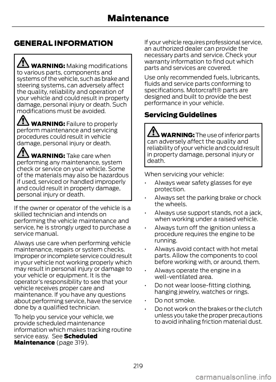
GENERAL INFORMATION
WARNING: Making modifications
to various parts, components and
systems of the vehicle, such as brake and
steering systems, can adversely affect
the quality, reliability and operation of
your vehicle and could result in property
damage, personal injury or death. Such
modifications must be avoided.
WARNING: Failure to properly
perform maintenance and servicing
procedures could result in vehicle
damage, personal injury or death.
WARNING: Take care when
performing any maintenance, system
check or service on your vehicle. Some
of the materials may also be hazardous
if used, serviced or handled improperly
and could result in property damage,
personal injury or death.
If the owner or operator of the vehicle is a
skilled technician and intends on
performing the vehicle maintenance and
service, he is strongly urged to purchase a
service manual.
Always use care when performing vehicle
maintenance, repairs or system checks.
Improper or incomplete service could result
in your vehicle not working properly which
may result in personal injury or damage to
your vehicle or equipment. It is the
operator’s responsibility to see that your
vehicle receives proper care and
maintenance. If you have any questions
about performing service, have the service
done by a qualified technician.
To help you service your vehicle, we
provide scheduled maintenance
information which makes tracking routine
service easy. See Scheduled
Maintenance (page 319).If your vehicle requires professional service,
an authorized dealer can provide the
necessary parts and service. Check your
warranty information to find out which
parts and services are covered.
Use only recommended fuels, lubricants,
fluids and service parts conforming to
specifications. Motorcraft® parts are
designed and built to provide the best
performance in your vehicle.
Servicing Guidelines
WARNING: The use of inferior parts
can adversely affect the quality and
reliability of your vehicle and could result
in property damage, personal injury or
death.
When servicing your vehicle:
• Always wear safety glasses for eye
protection.
• Always set the parking brake or chock
the wheels.
• Always use support stands, not a jack,
when working under a raised vehicle.
• Always turn off the ignition unless a
procedure requires the engine to be
running.
• Always avoid contact with hot metal
parts. Allow the components to cool
before working with, or around, them.
• Always operate the engine in a
well-ventilated area.
• Do not wear loose-fitting clothing,
hanging jewelry, watches or rings.
• Do not smoke.
• Do not work on the brakes or the clutch
unless you take the proper precautions
to avoid inhaling friction material dust.
219
Maintenance
Page 226 of 378
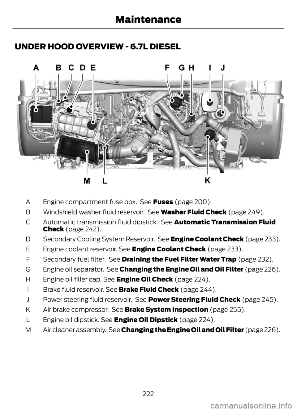
UNDER HOOD OVERVIEW - 6.7L DIESEL
E313700E313700
Engine compartment fuse box. See Fuses (page 200). A
Windshield washer fluid reservoir. See Washer Fluid Check (page 249). B
Automatic transmission fluid dipstick. See Automatic Transmission Fluid
Check (page 242). C
Secondary Cooling System Reservoir. See Engine Coolant Check (page 233). D
Engine coolant reservoir. See Engine Coolant Check (page 233). E
Secondary fuel filter. See Draining the Fuel Filter Water Trap (page 232). F
Engine oil separator. See Changing the Engine Oil and Oil Filter (page 226). G
Engine oil filler cap. See Engine Oil Check (page 224). H
Brake fluid reservoir. See Brake Fluid Check (page 244). I
Power steering fluid reservoir. See Power Steering Fluid Check (page 245). J
Air brake compressor. See Brake System Inspection (page 255). K
Engine oil dipstick. See Engine Oil Dipstick (page 224). L
Air cleaner assembly. See Changing the Engine Oil and Oil Filter (page 226). M
222
Maintenance
Page 231 of 378
• Sustained, high-speed driving at the
gross vehicle weight rating.
• Use of fuels with sulfur content other
than ultra-low sulfur diesel (ULSD).
• Use of high-sulfur diesel fuel.
Only use engine oil that meets our
specifications. See Capacities and
Specifications (page 288).
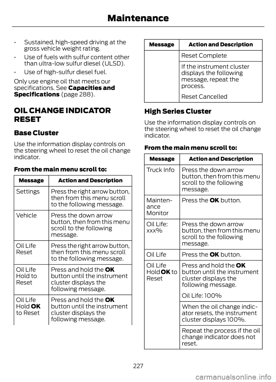
OIL CHANGE INDICATOR
RESET
Base Cluster
Use the information display controls on
the steering wheel to reset the oil change
indicator.
From the main menu scroll to:
Action and Description Message
Press the right arrow button,
then from this menu scroll
to the following message. Settings
Press the down arrow
button, then from this menu
scroll to the following
message. Vehicle
Press the right arrow button,
then from this menu scroll
to the following message. Oil Life
Reset
Press and hold the OK
button until the instrument
cluster displays the
following message. Oil Life
Hold to
Reset
Press and hold the OK
button until the instrument
cluster displays the
following message. Oil Life
Hold OK
to Reset
Action and Description Message
Reset Complete
If the instrument cluster
displays the following
message, repeat the
process.
Reset Cancelled
High Series Cluster
Use the information display controls on
the steering wheel to reset the oil change
indicator.
From the main menu scroll to:
Action and Description Message
Press the down arrow
button, then from this menu
scroll to the following
message. Truck Info
Press the OK button. Mainten-
ance
Monitor
Press the down arrow
button, then from this menu
scroll to the following
message. Oil Life:
xxx%
Press the OK button. Oil Life
Press and hold the OK
button until the instrument
cluster displays the
following message. Oil Life
Hold OK to
Reset
Oil Life: 100%
When the oil change indic-
ator resets, the instrument
cluster displays 100%.
Repeat the process if the oil
change indicator does not
reset.
227
Maintenance
Page 232 of 378
CHANGING THE ENGINE AIR
FILTER - 6.7L DIESEL
Air Filter Restriction Gauge
WARNING: To reduce the risk of
vehicle damage and personal burn
injuries, do not start your engine with the
air cleaner removed and do not remove
it while the engine is running.
Note:Operating your vehicle in heavy
snowfall or extreme rain conditions may
allow excessive amounts of snow or water
into the air intake system. This could plug
or soak the air filter and cause the engine to
lose power or shut down.
E163372
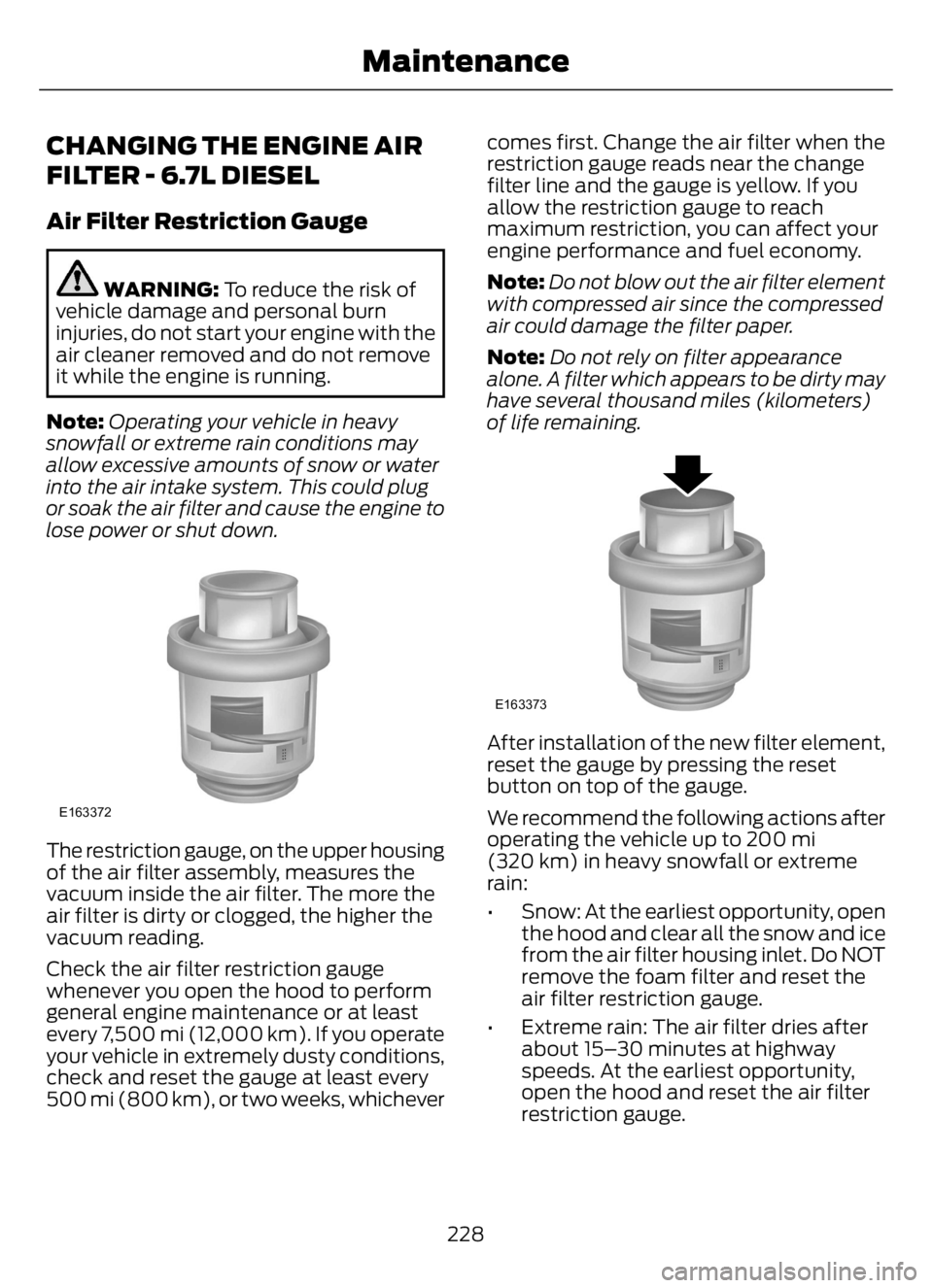
The restriction gauge, on the upper housing
of the air filter assembly, measures the
vacuum inside the air filter. The more the
air filter is dirty or clogged, the higher the
vacuum reading.
Check the air filter restriction gauge
whenever you open the hood to perform
general engine maintenance or at least
every 7,500 mi (12,000 km). If you operate
your vehicle in extremely dusty conditions,
check and reset the gauge at least every
500 mi (800 km), or two weeks, whichevercomes first. Change the air filter when the
restriction gauge reads near the change
filter line and the gauge is yellow. If you
allow the restriction gauge to reach
maximum restriction, you can affect your
engine performance and fuel economy.
Note:Do not blow out the air filter element
with compressed air since the compressed
air could damage the filter paper.
Note:Do not rely on filter appearance
alone. A filter which appears to be dirty may
have several thousand miles (kilometers)
of life remaining.
E163373
After installation of the new filter element,
reset the gauge by pressing the reset
button on top of the gauge.
We recommend the following actions after
operating the vehicle up to 200 mi
(320 km) in heavy snowfall or extreme
rain:
• Snow: At the earliest opportunity, open
the hood and clear all the snow and ice
from the air filter housing inlet. Do NOT
remove the foam filter and reset the
air filter restriction gauge.
• Extreme rain: The air filter dries after
about 15–30 minutes at highway
speeds. At the earliest opportunity,
open the hood and reset the air filter
restriction gauge.
228
Maintenance
Page 236 of 378
E317619E317619
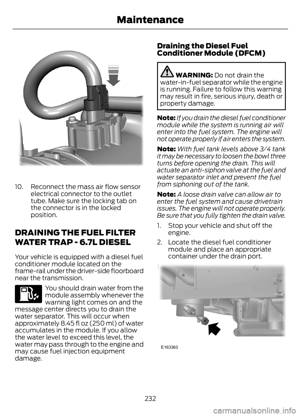
10. Reconnect the mass air flow sensor
electrical connector to the outlet
tube. Make sure the locking tab on
the connector is in the locked
position.
DRAINING THE FUEL FILTER
WATER TRAP - 6.7L DIESEL
Your vehicle is equipped with a diesel fuel
conditioner module located on the
frame-rail under the driver-side floorboard
near the transmission.
You should drain water from the
module assembly whenever the
warning light comes on and the
message center directs you to drain the
water separator. This will occur when
approximately 8.45 fl oz (250 ml) of water
accumulates in the module. If you allow
the water level to exceed this level, the
water may pass through to the engine and
may cause fuel injection equipment
damage.
Draining the Diesel Fuel
Conditioner Module (DFCM)
WARNING: Do not drain the
water-in-fuel separator while the engine
is running. Failure to follow this warning
may result in fire, serious injury, death or
property damage.
Note:If you drain the diesel fuel conditioner
module while the system is running air will
enter into the fuel system. The engine will
not operate properly if air enters the system.
Note:With fuel tank levels above 3⁄4 tank
it may be necessary to loosen the bowl three
turns before opening the drain. This will
actuate an anti-siphon valve at the fuel and
water separator inlet and prevent the fuel
from siphoning out of the tank.
Note:A loose drain valve can allow air to
enter the fuel system and cause drivetrain
issues. The engine will not operate properly.
Be sure that you fully tighten the drain valve.
1. Stop your vehicle and shut off the
engine.
2. Locate the diesel fuel conditioner
module and place an appropriate
container under the drain port.
E163360
232
Maintenance
Page 237 of 378
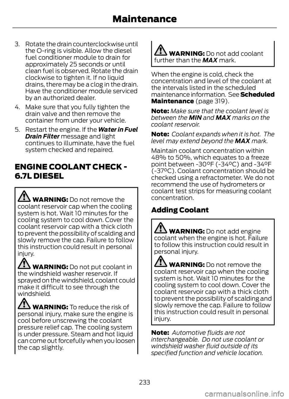
3. Rotate the drain counterclockwise until
the O-ring is visible. Allow the diesel
fuel conditioner module to drain for
approximately 25 seconds or until
clean fuel is observed. Rotate the drain
clockwise to tighten it. If no liquid
drains, there may be a clog in the drain.
Have the conditioner module serviced
by an authorized dealer.
4. Make sure that you fully tighten the
drain valve and then remove the
container from under your vehicle.
5. Restart the engine. If the Water in Fuel
Drain Filter message and light
continues to illuminate, have the fuel
system checked and repaired.
ENGINE COOLANT CHECK -
6.7L DIESEL
WARNING: Do not remove the
coolant reservoir cap when the cooling
system is hot. Wait 10 minutes for the
cooling system to cool down. Cover the
coolant reservoir cap with a thick cloth
to prevent the possibility of scalding and
slowly remove the cap. Failure to follow
this instruction could result in personal
injury.
WARNING: Do not put coolant in
the windshield washer reservoir. If
sprayed on the windshield, coolant could
make it difficult to see through the
windshield.
WARNING: To reduce the risk of
personal injury, make sure the engine is
cool before unscrewing the coolant
pressure relief cap. The cooling system
is under pressure. Steam and hot liquid
can come out forcefully when you loosen
the cap slightly.
WARNING: Do not add coolant
further than the MAX mark.
When the engine is cold, check the
concentration and level of the coolant at
the intervals listed in the scheduled
maintenance information. See Scheduled
Maintenance (page 319).
Note:Make sure that the coolant level is
between the MIN and MAX marks on the
coolant reservoir.
Note: Coolant expands when it is hot. The
level may extend beyond the MAX mark.
Maintain coolant concentration within
48% to 50%, which equates to a freeze
point between -30°F (-34°C) and -34°F
(-37°C). Coolant concentration should be
checked using a refractometer. We do not
recommend the use of hydrometers or
coolant test strips for measuring coolant
concentration.
Adding Coolant
WARNING: Do not add engine
coolant when the engine is hot. Failure
to follow this instruction could result in
personal injury.
WARNING: Do not remove the
coolant reservoir cap when the cooling
system is hot. Wait 10 minutes for the
cooling system to cool down. Cover the
coolant reservoir cap with a thick cloth
to prevent the possibility of scalding and
slowly remove the cap. Failure to follow
this instruction could result in personal
injury.
Note: Automotive fluids are not
interchangeable. Do not use coolant or
windshield washer fluid outside of its
specified function and vehicle location.
233
Maintenance
Page 241 of 378
•Robinair® Coolant and Battery
Refractometer 75240 –
Recommended refractometer to test
coolant concentration. (Rotunda tool
part number: ROB75240).
•Rotunda 328-R071–ELC (Antifreeze
Coolant ELC Contamination Kit) –
Evaluates the corrosion inhibitor
additive strength.
• The first step is once the coolant
concentration is verified to be in the
range of 40 – 60%. Test the
corrosion inhibitor additive
strength. If the test results show
the cooling system does not have
excessive contamination and the
corrosion inhibitor additive strength
is sufficient then no further action
is required. If the test results for the
Engine Coolant Circuit show the
cooling system has excessive
contamination or the corrosion
inhibitor additive strength is not
sufficient then add 47 fl oz (1.4 L)
of Motorcraft Specialty Orange
Engine Coolant Revitalizer. If the
test results for the Secondary
Coolant Circuit show the cooling
system has excessive
contamination or the corrosion
inhibitor additive strength is not
sufficient then add 16 fl oz (0.47 L)
of Motorcraft Specialty Orange
Engine Coolant Revitalizer.
•Motorcraft Specialty Orange Engine
Coolant Revitalizer – Additive to
boost the corrosion inhibitor level
based upon the test results of the
Antifreeze Coolant ELC Contamination
Kit. The Revitalizer may be added two
times over the life of the coolant. If
additional dosages are required, the
cooling system must be flushed and
refilled per the instructions in the
Workshop Manual.Make sure to follow the proper coolant and
additive specifications. See Capacities
and Specifications (page 288).
Coolant Change
At specific mileage intervals, as listed in
the scheduled maintenance information,
the coolant should be changed. The
information display may display a message
to change coolant at this time. Add
prediluted coolant approved to the correct
specification. See Capacities and
Specifications (page 288).
Engine-driven Cooling Fan (Fan
Clutch)
Your vehicle may have an engine driven
cooling fan drive (also called a fan clutch).
This fan drive changes the fan speed to
match the vehicle’s changing cooling air
flow requirements. Fan speed, fan noise
level and fuel consumption all will increase
based on the driving conditions that
include trailer towing, hill climbing, heavy
loads, high speed and high ambient
temperature, individually or in combination.
The fan drive is designed to provide the
minimum fan speed (and resulting
minimum fan noise and fuel consumption)
required to meet the ever changing vehicle
cooling air flow requirements. You will hear
the amount of fan noise increasing and
decreasing as the engine power
requirements and vehicle driving conditions
change as you drive. This is to be expected
as being normal to the operation of your
vehicle. High levels of fan noise might also
be heard when your engine is first started,
and should normally decrease after driving
for a short time.
237
Maintenance
Page 244 of 378
Do not use the following as a coolant
substitute:
• Alcohol.
• Methanol.
• Brine.
• Any coolant mixed with alcohol or
methanol antifreeze.
Alcohol and other liquids can cause engine
damage from overheating or freezing.
Do not add extra inhibitors or additives to
the coolant. These can be harmful and
compromise the corrosion protection of
the coolant.
Recycled Coolant
We do not recommend the use of recycled
coolant as an approved recycling process
is not yet available.
Dispose of used engine coolant in an
appropriate manner. Follow your
community’s regulations and standards
for recycling and disposing of automotive
fluids.
Severe Climates
If you drive in extremely cold climates:
• It may be necessary to increase the
coolant concentration above 50%.
• A coolant concentration of 60%
provides improved freeze point
protection. Coolant concentrations
above 60% decrease the overheat
protection characteristics of the
coolant and may cause engine
damage.If you drive in extremely hot climates:
• You can decrease the coolant
concentration to 40%.
• Coolant concentrations below 40%
decrease the freeze and corrosion
protection characteristics of the
coolant and may cause engine
damage.
Vehicles driven year-round in non-extreme
climates should use prediluted engine
coolant for optimum cooling system and
engine protection.
Coolant Change
Change the coolant at specific mileage
intervals as listed in the scheduled
maintenance information. The information
display may display a message to change
coolant at this time. Add prediluted
coolant approved to the correct
specification. See Capacities and
Specifications (page 288).
Engine-driven Cooling Fan (Fan
Clutch)
Your vehicle comes with an engine driven
cooling fan drive, also called a fan clutch.
This fan drive changes the fan speed to
match the vehicle’s changing cooling air
flow requirements. Fan speed, fan noise
level and fuel consumption all will increase
based on the driving conditions that
include trailer towing, hill climbing, heavy
loads, high speed and high ambient
temperature, individually or in combination.
The fan drive is designed to provide the
minimum fan speed, and resulting
minimum fan noise and fuel consumption
required to meet the ever changing vehicle
cooling air flow requirements. You will hear
the amount of fan noise increasing and
decreasing as the engine power
requirements and vehicle driving conditions
240
Maintenance
Page 250 of 378
CHANGING THE 12V BATTERY
WARNING: This vehicle may be
equipped with more than one battery,
removal of cable from only one battery
does not disconnect the vehicle
electrical system. Be sure to disconnect
cables from all batteries when
disconnecting power. Failure to do so
may cause serious personal injury or
property damage.
WARNING: Batteries normally
produce explosive gases which can
cause personal injury. Therefore, do not
allow flames, sparks or lighted
substances to come near the battery.
When working near the battery, always
shield your face and protect your eyes.
Always provide proper ventilation.
WARNING: When lifting a
plastic-cased battery, excessive pressure
on the end walls could cause acid to flow
through the vent caps, resulting in
personal injury and damage to the
vehicle or battery. Lift the battery with a
battery carrier or with your hands on
opposite corners.
WARNING: Keep batteries out of
reach of children. Batteries contain
sulfuric acid. Avoid contact with skin,
eyes or clothing. Shield your eyes when
working near the battery to protect
against possible splashing of acid
solution. In case of acid contact with skin
or eyes, flush immediately with water for
a minimum of 15 minutes and get prompt
medical attention. If acid is swallowed,
call a physician immediately.
Note:If your battery has a cover/shield,
make sure it is reinstalled after the battery
has been cleaned or replaced.Note:Battery posts, terminals and related
accessories contain lead and lead
compounds. Wash hands after handling.
Note:Electrical or electronic accessories
or components added to the vehicle by the
dealer or the owner may adversely affect
battery performance and durability.
Your vehicle is equipped with a Motorcraft
maintenance-free battery which normally
does not require additional water during
its life of service.
For longer, trouble-free operation, keep the
top of the battery clean and dry. Also,
make certain the battery cables are always
tightly fastened to the battery terminals.
If you see any corrosion on the battery or
terminals, remove the cables from the
terminals and clean with a wire brush. You
can neutralize the acid with a solution of
baking soda and water.
It is recommended that the negative
battery cable terminal be disconnected
from the battery if you plan to store your
vehicle for an extended period of time.
Because your vehicle’s engine is
electronically controlled by a computer,
some control conditions are maintained
by power from the battery. When the
battery is disconnected or a new battery
is installed, the engine must relearn its idle
and fuel trim strategy for optimum
driveability and performance. To begin this
process
1. With the vehicle at a complete stop,
set the parking brake.
2. Put the gearshift in park (P) or neutral
(N) and turn off all accessories.
3. Start the engine. Run the engine until
it reaches normal operating
temperature.
4. Allow the engine to idle for at least one
minute.
246
Maintenance