check engine FORD F650/750 2024 Owner's Manual
[x] Cancel search | Manufacturer: FORD, Model Year: 2024, Model line: F650/750, Model: FORD F650/750 2024Pages: 386, PDF Size: 8.7 MB
Page 122 of 386
•Incorrect fuel for climatic conditions.
•Incorrect engine oil viscosity forclimactic conditions.
Note:Some vehicles have a lifetime fuelfilter that is integrated with the fuel tank.Regular maintenance or replacement is notneeded.
Note:If these checks do not help youcorrect the concern, have your vehiclechecked as soon as possible.
Noise Emissions Warranty,Prohibited Tampering Acts andMaintenance
On January 1, 1978, Federal regulationbecame effective governing the noiseemission on trucks over 10,000 lb(4,536 kg) Gross Vehicle Weight Rating(GVWR). The preceding statementsconcerning prohibited tampering acts andmaintenance, and the noise warrantyfound in the Warranty Guide, areapplicable to complete chassis cabs over10,000 lb (4,536 kg) GVWR.
CATALYTIC CONVERTER
WARNING: Do not park, idle ordrive your vehicle on dry grass or otherdry ground cover. The emission systemheats up the engine compartment andexhaust system, creating the risk of fire.
WARNING: The normal operatingtemperature of the exhaust system isvery high. Never work around or attemptto repair any part of the exhaust systemuntil it has cooled. Use special care whenworking around the catalytic converter.The catalytic converter heats up to a veryhigh temperature after only a shortperiod of engine operation and stays hotafter the engine is switched off.
WARNING: Exhaust leaks mayresult in entry of harmful and potentiallylethal fumes into the passengercompartment. If you smell exhaustfumes inside your vehicle, have yourvehicle inspected immediately. Do notdrive if you smell exhaust fumes.
Your vehicle has various emission controlcomponents and a catalytic converter thatenables it to comply with applicableexhaust emission standards.
To make sure that the catalytic converterand other emission control componentscontinue to work properly:
•Do not crank the engine for more than10 seconds at a time.
•Do not run the engine with a spark pluglead disconnected.
•Do not push-start or tow-start yourvehicle. Use booster cables. See JumpStarting the Vehicle (page 190).
•Use only the specified fuel listed.
•Do not switch the ignition off when yourvehicle is moving.
•Avoid running out of fuel.
•Have the items listed in scheduledmaintenance information performedaccording to the specified schedule.
Note:Resulting component damage maynot be covered by the vehicle Warranty.
The scheduled maintenance items listedin scheduled maintenance information areessential to the life and performance ofyour vehicle and to its emissions system.
If you use anything other than Ford,Motorcraft or Ford-authorized parts formaintenance replacements or for serviceof components affecting emission control,such non-Ford parts should be equivalentto genuine Ford Motor Company parts inperformance and durability.
118
2024 F-650/750 (TBC) , enUSA, Edition date: 202210, First-PrintingEngine Emission Control
Page 124 of 386
Your vehicle may not pass the I/M test ifthe service engine soon indicator is on ornot working properly (bulb is burned out),or if the OBD-II system has determinedthat some of the emission control systemshave not been properly checked. In thiscase, the vehicle is not ready for I/Mtesting.
If the vehicle’s engine or transmission hasjust been serviced, or the battery hasrecently run down or been replaced, theOBD-II system may indicate that thevehicle is not ready for I/M testing. Todetermine if the vehicle is ready for I/Mtesting, turn the ignition key to the onposition for 15 seconds without crankingthe engine. If the service engine soonindicator blinks eight times, it means thatthe vehicle is not ready for I/M testing; ifthe service engine soon indicator stays onsolid, it means that your vehicle is readyfor I/M testing.
The OBD-II system checks the emissioncontrol system during normal driving. Acomplete check may take several days.
If the vehicle is not ready for I/M testing,you can perform the following driving cycleconsisting of mixed city and highwaydriving:
1.15 minutes of steady driving on anexpressway or highway followed by 20minutes of stop-and-go driving with atleast four 30-second idle periods.
2.Allow your vehicle to sit for at leasteight hours with the ignition off. Then,start the vehicle and complete theabove driving cycle. The vehicle mustwarm up to its normal operatingtemperature. Once started, do not turnoff the vehicle until the above drivingcycle is complete.
If the vehicle is still not ready for I/Mtesting, you need to repeat the abovedriving cycle.
SELECTIVE CATALYTIC
REDUCTANT SYSTEM - DIESEL
Your vehicle may have a selective catalyticreduction system. This system helpsreduce emission levels of oxides ofnitrogen from the exhaust system. Thesystem automatically injects dieselexhaust fluid into the exhaust system toenable correct selective catalytic reductionsystem function.
Note:Selective catalytic reduction systemsare not fitted to vehicles in markets whereonly high-sulfur diesel fuel is available.
Diesel Exhaust Fluid Level
In order for the system to operate correctlyyou must maintain the diesel exhaust fluidlevel.
The system has a sensor to monitor fluidlevel and quality/concentration. A warningmessage appears in the informationdisplay when the diesel exhaust fluid levelis low. If a warning message appears, refillthe diesel exhaust fluid tank as soon aspossible. See Information Messages(page 75).
Filling the Diesel Exhaust FluidTank
WARNING: Keep diesel exhaustfluid out of reach of children. Avoidcontact with skin, eyes or clothing. Incase of contact with your eyes, flushimmediately with water and get promptmedical attention. In case of contactwith your skin, clean immediately withsoap and water. If you swallow anydiesel exhaust fluid, drink plenty ofwater, call a physician immediately.
120
2024 F-650/750 (TBC) , enUSA, Edition date: 202210, First-PrintingEngine Emission Control
Page 126 of 386
1.Remove the diesel exhaust fluidcontainer cap. Place the spout onto thecontainer and tighten until you feel astrong resistance.
2.Remove the diesel exhaust fluid tankfiller cap.
3.Insert the spout into the filler neck untilthe seal on the spout seats onto thefiller neck. Pour the fluid into the tank.When the tank is full the fluid stops. Incase of direct fill tank, the spout doesnot seal against the fill tank interfaceand does not stop the flowingautomatically.
4.Return the container to the verticalposition slightly below the dieselexhaust fluid filler neck. Allow any fluidremaining in the spout to drain backinto the container.
5.Remove the spout from the dieselexhaust fluid filler neck. Replace thediesel exhaust fluid tank cap.
6.Remove the spout from the dieselexhaust fluid container and replace thecap.
Note:If there is diesel exhaust fluid left inthe container retain it for later use. Thespout is reusable. Wash the spout withclean water prior to storage. Do not use thediesel exhaust fluid spout with any otherfluid.
Filling the Diesel Exhaust Fluid Tank inCold Climates
Diesel exhaust fluid freezes if the ambienttemperature is below 12°F (-11°C). Yourvehicle has a preheating system whichallows diesel exhaust fluid to operatebelow 12°F (-11°C). If you do not use yourvehicle for an extended period when theambient temperature is below 12°F (-11°C),the fluid in the tank freezes. If the tank isoverfilled and the fluid freezes it maydamage the tank. This is not covered bythe vehicle warranty.
Note: If the diesel exhaust fluid tank isfrozen, it may not recognize when the tankis refilled. The diesel exhaust fluid levelupdates once the tank thaws out.
Diesel Exhaust Fluid WarningMessages and Vehicle Operations
WARNING: Diesel exhaust fluidmust be refilled when low or replacedwhen contaminated or your vehiclespeed becomes limited to 50 mph(80 km/h). In these conditions, drive withcaution and refill diesel exhaust fluidimmediately. If the diesel exhaust fluidbecomes empty or contaminated andfluid is not replaced, your vehiclebecomes limited to engine idle only oncestopped. In these conditions, be cautiouswhere you stop your vehicle because youmay not be able to drive long distancesor maintain highway speeds until yourefill or replace the diesel exhaust fluid.
Note:Drain and replace diluted dieselexhaust fluid.
WARNING: Tampering with ordisabling the selective catalyticreduction system results in severevehicle performance limitation includingeventual speed limiting to 5 mph(8 km/h).
A systems check displays messagesindicating the amount of diesel exhaustfluid available or displays a warningmessage indicating the approximatedistance remaining as the fluid in the dieselexhaust fluid tank nears empty. SeeInformation Messages (page 75).
122
2024 F-650/750 (TBC) , enUSA, Edition date: 202210, First-PrintingEngine Emission Control
Page 132 of 386
Information Display Procedure
Start your vehicle engine and when it hasreached the normal operating temperature,arrow through the display to get to theDiesel Particulate Filter Status on theTruck Info tab. Exhaust Filter XX%/FULLdisplays. Operator commandedregeneration can only be initiated whenFULL See Information Display Control(page 53). If a message advising that theexhaust filter is full appears in theinformation display, press and hold the OKbutton to initiate Exhaust Cleaning. Ifsuccessful, a second prompt appearsregarding exhaust position required toinitiate operator commanded regeneration.Be sure to understand each prompt. If youare not sure what is being asked by eachprompt, contact an authorized dealer. Ifthe exhaust system meets the positionrequirements then press and hold the OKbutton to fully activate the OperatorCommanded Regeneration. The displayconfirms the operation has started andwhen it has finished.
You can also drive to clean the filter.
When the system is at the pointof oversaturation, the serviceengine warning lamp illuminatesand a message appears in the informationdisplay. You cannot initiate filter cleaning.You must have your vehicle checked assoon as possible.
Once operator commanded regenerationstarts, engine speed increases toapproximately 1200 rpm and the coolingfan speed may increase. You will hear achange in audible sound due to enginespeed and cooling fan speed increases.
It is not necessary to open the hood on theengine compartment. Once operatorcommanded regeneration completes, theengine speed returns to normal idling. Theexhaust system remains very hot forseveral minutes even after regeneration is
complete. Do not reposition the vehicleover materials that could burn until theexhaust system has had sufficient time tocool. Depending on the amount of sootcollected by the diesel particulate filter,ambient temperature and altitude,operator commanded regeneration lastsapproximately 30 minutes.
Operator Commanded Regenerationwith Automatic Regeneration Control(If Equipped)
If your vehicle is operated with significantstationary operation, low speed drivecycles less than 25 mph (40 km/h), shortdrive cycles, drive time less than 15 minutesor the vehicle does not fully warm up,passive and active regeneration may notsufficiently clean the diesel particulatefilter system. You can switch off automaticregeneration until better driving conditionsare available, for example steady highspeed driving. You can then switchautomatic regeneration back on to cleanthe diesel particulate filter.
Switching Automatic RegenerationControl On and Off
To switch operator commandedregeneration on and off, use theinformation display control on the steeringwheel. See Information Display Control(page 53). Scroll through the Settings tabto ensure there is a check in the box nextto Auto Regeneration, this means it isactive. To deactivate Auto Regeneration,uncheck the box. A message appears “AutoExhaust Cleaning Off” along with an iconindicating that Auto Exhaust Cleaning isdisabled. The icon stays illuminated untilyou switch Auto Exhaust Cleaning back onby checking the box.
128
2024 F-650/750 (TBC) , enUSA, Edition date: 202210, First-PrintingEngine Emission ControlE67028
Page 133 of 386
How to Interrupt or Cancel OperatorCommanded Regeneration
If you need to cancel the operatorcommanded regeneration, pressing thebrake, accelerator or switching the engineoff stops the procedure. Depending on theamount of time you allowed the operatorcommanded regeneration to operate, sootmay not have had sufficient time to be fullyeliminated, but the exhaust system andexhaust gas may still be hot. If you shutyour vehicle off during operatorcommanded regeneration, you may noticeturbo flutter. This is a normal consequencecaused by shutting off a diesel engineduring boosted operation and is considerednormal.
Filter Service and Maintenance
Over time, a slight amount of ash buildsup in the diesel particulate filter, which isnot removed during the regenerationprocess. The filter may need to be replacedwith a new or remanufactured part atapproximately 250,000 mi (400,000 km).Actual mileage varies depending on engineand vehicle operating conditions.
If filter service is required, theengine control system warninglamp illuminates in theinformation display.
If there are any issues with thediesel particulate filter system,the engine control systemwarning lamp and a serviceengine soon warning lampilluminate to inform you thatyour vehicle requires service. Have yourvehicle checked as soon as possible.
Resonator and Tailpipe AssemblyMaintenance
Aftermarket devices or modifications tothe exhaust system may reduce theeffectiveness of the exhaust system aswell as cause damage to the exhaustsystem or engine. This may also degradevehicle performance and could lead toengine damage that may not be coveredby the vehicle Warranty.
129
2024 F-650/750 (TBC) , enUSA, Edition date: 202210, First-PrintingEngine Emission Control E67028
Page 143 of 386
GENERAL INFORMATION
Note: Occasional brake noise is normal. Ifa metal-to-metal, continuous grinding orcontinuous squeal sound is present, thebrake linings may be worn-out. Have thesystem checked as soon as possible. If thevehicle has continuous vibration or shudderin the steering wheel while braking, have thesystem checked as soon as possible.
All standard equipment brakes areself-adjusting. Automatic adjustment,when required, occurs whenever you applyand release the brakes during forward orreverse operation.
Know the required stopping distances forall driving conditions you may encounter.For longer brake lining life, take fulladvantage of engine braking power whencoming to a stop.
Wet brakes result in reduced brakingefficiency. Gently press the brake pedal afew times when driving from a car wash orstanding water to dry the brakes.
If the brakes do not grip well:
•Check brake adjustment.
•Check the brake linings for excessivewear.
•Check the system air pressure onvehicles with air brakes.
•Let the brakes cool if you have beenusing them excessively, as in mountaindriving or after several fast, high-speedstops.
•If you have been driving through deepwater, gently apply the brakes severaltimes while your vehicle is movingslowly.
Brake Over Accelerator
In the event the accelerator pedalbecomes stuck or entrapped, apply steadyand firm pressure to the brake pedal toslow the vehicle and reduce engine power.If you experience this condition, apply thebrakes and bring your vehicle to a safestop. Move the transmission to park (P),switch the engine off and apply the parkingbrake. Inspect the accelerator pedal forany interference. If none are found and thecondition persists, have your vehicle towedto the nearest authorized dealer
Anti-lock Brake System
This system helps you maintain steeringcontrol during emergency stops by keepingthe brakes from locking.
If the light does not illuminateduring start up, remains on orflashes, the system may bedisabled. It also momentarily illuminateswhen you switch the ignition on to confirmthe lamp is functional. If it does notilluminate when you switch the ignition on,or begins to flash at any time, have thesystem checked.
If you connect a PLC trailer withthe ignition on, the trailer ABSlight also illuminates. If the lightfails to illuminate, if it remains on after youstart the vehicle or continues to flash, havethe system serviced immediately.
See Warning Lamps and Indicators(page 67).
139
2024 F-650/750 (TBC) , enUSA, Edition date: 202210, First-PrintingBrakesE67020 E210335
Page 148 of 386
Vehicles with Automatic Transmission
When you switch the ignition on, thesystem automatically turns on. You cannotturn the system on or off.
AIR BRAKES
WARNING: Failure to maintainproper air brake adjustment can resultin reduction or loss of braking ability.
WARNING: Do not drive or continueto drive if the low air pressure buzzer issounding or the brake warning light is lit.These warnings indicate that air pressureis not to normal operating level.Continued use of the vehicle could resultin loss of braking ability.
WARNING: Avoid repeated lightapplication of the brake pedal. Thisdepletes air pressure faster and couldresult in loss of braking capability.
WARNING: Do not move thevehicle when the air pressure isinsufficient because the brake systemmay be inoperative.
After starting the engine, allow time for theair compressor to build air pressure to60 psi (414 kPa) before moving yourvehicle.
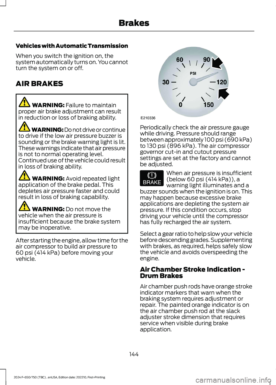
Periodically check the air pressure gaugewhile driving. Pressure should rangebetween approximately 100 psi (690 kPa)to 130 psi (896 kPa). The air compressorgovernor cut-in and cutout pressuresettings are set at the factory and cannotbe adjusted.
When air pressure is insufficient(below 60 psi (414 kPa)), awarning light illuminates and abuzzer sounds when the ignition is on. Thismay happen because excessive brakeapplications are depleting the system airpressure. If this condition occurs, stopdriving your vehicle until the compressorhas fully recharged the air system.
Select a gear ratio to help slow your vehiclebefore descending grades. Supplementingwith brakes, as required, helps safely slowthe vehicle and avoids overspeeding theengine.
Air Chamber Stroke Indication -Drum Brakes
Air chamber push rods have orange strokeindicator markers that warn when thebraking system requires adjustment orrepair. The painted orange indicator is onthe air chamber push rod at the slackadjuster stroke dimension that requiresservice when visible during brakeapplication.
144
2024 F-650/750 (TBC) , enUSA, Edition date: 202210, First-PrintingBrakesE210336 E206772
Page 155 of 386
PRINCIPLE OF OPERATION
The traction control system helps avoiddrive wheel spin and loss of traction.
If your vehicle begins to slide, the systemapplies the brakes to individual wheelsand, when needed, reduces engine powerat the same time. If the wheels spin whenaccelerating on slippery or loose surfaces,the system reduces engine power in orderto increase traction.
USING TRACTION CONTROL -
VEHICLES WITH: AIR BRAKES
WARNING: Operating your vehiclewith the traction control disabled couldlead to an increased risk of loss of vehiclecontrol, vehicle rollover, personal injuryand death.
Press the TCS Off button on theinstrument panel to enable themud/snow mode.
This is beneficial when your vehicle is stuckin snow or on a slippery road surface. Thismode allows wheel spin to dig your vehicleout and allows you to rock your vehicle.
Press the switch again to select standardtraction control. The system automaticallyselects standard traction control at thenext ignition cycle.
System Indicator Light
Note:If the traction control light does notflash during a traction control event or staysilluminated, the system is not functioningproperly. Take your vehicle to an authorizeddealer for service.
During traction control operation, thetraction control light flashes rapidly andthe engine does not rev-up when you pressfurther on the accelerator. This is normaland is no reason for concern.
In mud/snow mode, the TCS OFF lightilluminates on the instrument cluster. If atraction event occurs in either mode, thestability and traction control light flashesrapidly.
USING TRACTION CONTROL -
VEHICLES WITH: HYDRAULIC
BRAKES
WARNING: Operating your vehiclewith the traction control disabled couldlead to an increased risk of loss of vehiclecontrol, vehicle rollover, personal injuryand death.
The system turns on each time you switchthe ignition on.
Use the traction control buttonon the instrument panel toswitch the system off or on.
If your vehicle is stuck in mud or snow,switching traction control off is beneficialas this allows the wheels to spin.
Press the button again to switch thetraction control system on.
System Indicator Light
Note:If the traction control light does notflash during a traction control event or stayson, the system is not operating. Have thesystem checked as soon as possible.
During a traction control event, the tractioncontrol light rapidly flashes. Pressingfurther on the accelerator does not causethe engine to rev higher. This is normal andis no reason for concern.
151
2024 F-650/750 (TBC) , enUSA, Edition date: 202210, First-PrintingTraction ControlE330660 E330660
Page 167 of 386
Hilly Condition and Trailer TowUsage
You should select a lower gear when thesystem is active in situations such asprolonged downhill driving on steepgrades, for example in mountainous areas.The system needs additional enginebraking in these situations to reduce theload on the vehicle’s regular brake systemto prevent it from overheating.
Note:An audible alarm sounds and thesystem shuts down if it applies brakes foran extended period of time. This allows thebrakes to cool. The system functionsnormally again after the brakes cool.
Note:When towing with adaptive cruisecontrol, switch on Tow/Haul mode.
Switching Adaptive Cruise ControlOff
Press and release the buttonwhen the system is in standbymode, or switch the ignition off.
Note:The set speed and gap setting iserased when you switch the system off.
Detection Issues
WARNING: On rare occasions,detection issues can occur due to theroad infrastructures, for example bridges,tunnels and safety barriers. In thesecases, the system may brake late orunexpectedly. At all times, you areresponsible for controlling your vehicle,supervising the system and intervening,if required.
WARNING: If the systemmalfunctions, have your vehicle checkedas soon as possible.
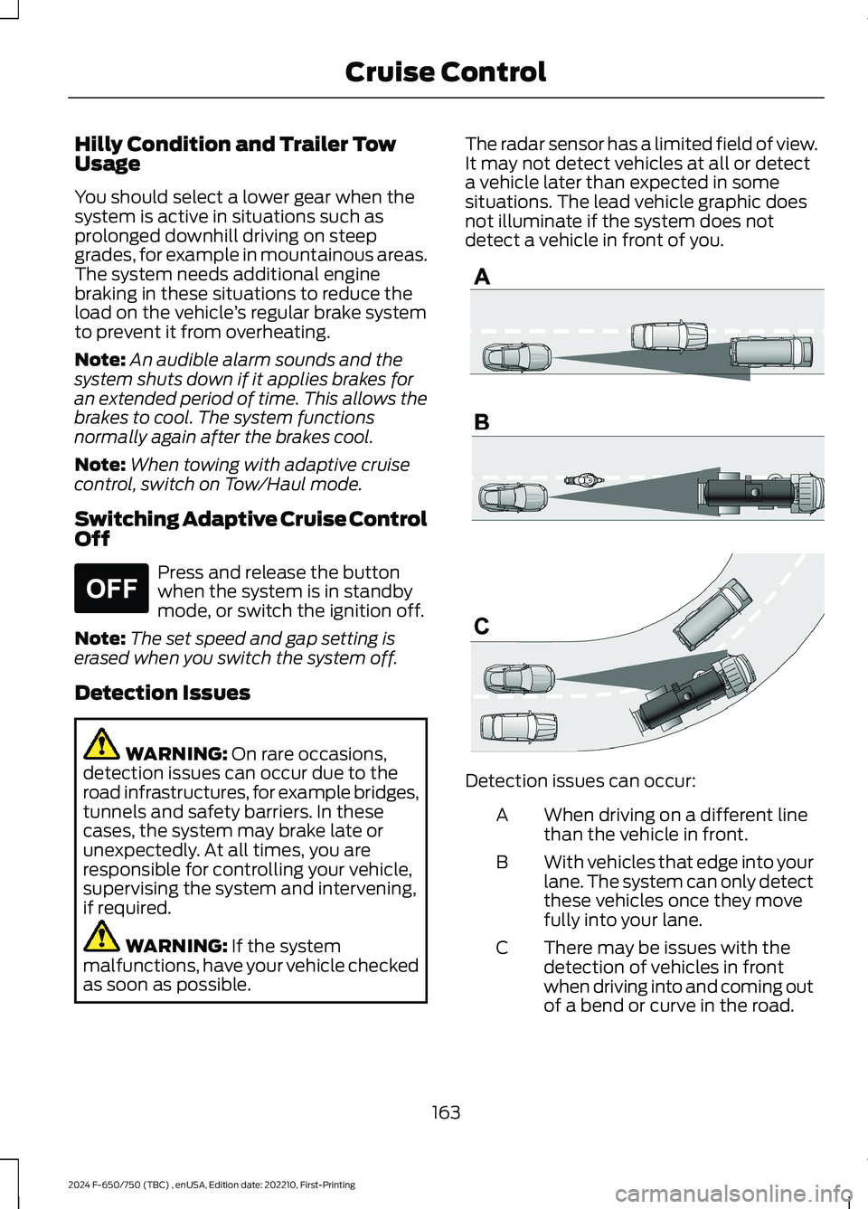
The radar sensor has a limited field of view.It may not detect vehicles at all or detecta vehicle later than expected in somesituations. The lead vehicle graphic doesnot illuminate if the system does notdetect a vehicle in front of you.
Detection issues can occur:
When driving on a different linethan the vehicle in front.A
With vehicles that edge into yourlane. The system can only detectthese vehicles once they movefully into your lane.
B
There may be issues with thedetection of vehicles in frontwhen driving into and coming outof a bend or curve in the road.
C
163
2024 F-650/750 (TBC) , enUSA, Edition date: 202210, First-PrintingCruise ControlE265297 E71621
Page 174 of 386
STEERING
Hydraulic Power Steering
To help prevent damage to the powersteering system:
•Do not hold the steering wheel at itsfurthest turning points for more thanthree to five seconds when the engineis running.
•Avoid continuously steering back andforth with elevated engine RPM as thismay overheat the system. If trying tofree a stuck vehicle, pause betweenattempts to allow the power steeringsystem to cool or seek assistance.Typical steering and driving maneuversallow the system to cool.
•Do not operate the vehicle if the powersteering pump fluid level is below theMIN mark on the reservoir.
•Some noise is normal during operation.If excessive, check for low powersteering pump fluid level beforeseeking service by your dealer.
•Heavy or uneven efforts may be causedby low power steering fluid. Check forlow power steering pump fluid levelbefore seeking service by your dealer.
•Do not fill the power steering pumpreservoir above the MAX mark on thereservoir, as this may result in leaksfrom the reservoir.
If the power steering system breaks downor if you switch the engine off, you cansteer the vehicle manually, but it takesmore effort.
If you have any steering componentsserviced or replaced, install new fasteners.Many fasteners have coatings with threadadhesive, or have prevailing torquefeatures you cannot reuse. Do not reuse abolt or nut. Torque fasteners tospecifications.
Steering Tips
If the steering wanders or pulls, check for:
•An improperly inflated tire.
•Uneven tire wear.
•Loose or worn suspensioncomponents.
•Loose or worn steering components.
•Improper vehicle alignment.
Note:A high crown in the road or highcrosswinds may also make the steeringseem to wander or pull.
PRE-COLLISION ASSIST -
VEHICLES WITH: AIR BRAKES
WARNING: You are responsible forcontrolling your vehicle at all times. Thesystem is designed to be an aid and doesnot relieve you of your responsibility todrive with due care and attention. Failureto follow this instruction could result inthe loss of control of your vehicle,personal injury or death.
WARNING: The system does notdetect vehicles that are driving in adifferent direction, pedestrians, cyclistsor animals. Apply the brakes whennecessary. Failure to follow thisinstruction could result in the loss ofcontrol of your vehicle, personal injury ordeath.
170
2024 F-650/750 (TBC) , enUSA, Edition date: 202210, First-PrintingDriving Aids