check engine FORD F650/750 2024 Workshop Manual
[x] Cancel search | Manufacturer: FORD, Model Year: 2024, Model line: F650/750, Model: FORD F650/750 2024Pages: 386, PDF Size: 8.7 MB
Page 246 of 386
If the engine reaches a presetover-temperature condition, the engineswitches to alternating cylinder operation.Each disabled cylinder acts as an air pumpand cools the engine.
When this occurs, your vehicle stilloperates, however:
•Engine power is limited.
•The air conditioning system turns off.
Continued operation increases the enginetemperature, causing the engine tocompletely shut down. Your steering andbraking effort increases in this situation.
When the engine temperature cools, youcan re-start the engine. Have your vehiclechecked as soon as possible to minimizeengine damage.
When Fail-Safe Mode Is Activated
WARNING: Fail-safe mode is foruse during emergencies only. Operateyour vehicle in fail-safe mode only aslong as necessary to bring your vehicleto rest in a safe location and seekimmediate repairs. When in fail-safemode, your vehicle will have limitedpower, will not be able to maintainhigh-speed operation, and maycompletely shut down without warning,potentially losing engine power, powersteering assist, and power brake assist,which may increase the possibility of acrash resulting in serious injury.
WARNING: Do not remove thecoolant reservoir cap when the engine ison or the cooling system is hot. Wait 10minutes for the cooling system to cooldown. Cover the coolant reservoir capwith a thick cloth to prevent thepossibility of scalding and slowly removethe cap. Failure to follow this instructioncould result in personal injury.
Your vehicle has limited engine powerwhen in the fail-safe mode, drive yourvehicle with caution. Your vehicle does notmaintain high-speed operation and theengine may operate poorly.
Remember that the engine is capable ofshutting down to prevent engine damage.In this situation:
1.Pull off the road as soon as safelypossible and switch the engine off.
2.If you are a member of a roadsideassistance program, we recommendthat you contact your roadsideassistance service provider.
3.If this is not possible, wait a shortperiod for the engine to cool.
4.Check the coolant level. If the coolantlevel is at or below the minimum mark,add prediluted coolant immediately.
5.When the engine temperature cools,you can re-start the engine. Have yourvehicle checked as soon as possible tominimize engine damage.
Note: Driving your vehicle without repairincreases the chance of engine damage.
Engine Coolant TemperatureManagement (If Equipped)
WARNING: To reduce the risk ofcrash and injury, be prepared that thevehicle speed may reduce and thevehicle may not be able to acceleratewith full power until the coolanttemperature reduces.
If you tow a trailer with your vehicle, theengine may temporarily reach a highertemperature during severe operatingconditions, for example ascending a longor steep grade in high ambienttemperatures.
242
2024 F-650/750 (TBC) , enUSA, Edition date: 202210, First-PrintingMaintenance
Page 247 of 386
At this time, you may notice the coolanttemperature gauge moves toward the redzone and a message may appear in theinformation display.
You may notice a reduction in vehiclespeed caused by reduced engine power inorder to manage the engine coolanttemperature. Your vehicle may enter thismode if certain high-temperature andhigh-load conditions take place. Theamount of speed reduction depends onvehicle loading, grade and ambienttemperature. If this occurs, there is noneed to pull off the road. You can continueto drive your vehicle.
The air conditioning may turn on and offduring severe operating conditions toprotect the engine from overheating. Whenthe coolant temperature decreases to thenormal operating temperature, the airconditioning turns on.
If the coolant temperature gauge movesfully into the red zone, or if the coolanttemperature warning or service enginesoon messages appear in your informationdisplay, do the following:
1.Pull off the road as soon as safelypossible and shift the transmission intopark (P).
2.Leave the engine running until thecoolant temperature gauge needlereturns to the normal position. Afterseveral minutes, if the temperaturedoes not drop, follow the remainingsteps.
3.Switch the engine off and wait for it tocool. Check the coolant level.
4.If the coolant level is at or below theminimum mark, add prediluted coolantimmediately.
5.If the coolant level is normal, restartthe engine and continue.
AUTOMATIC TRANSMISSION
FLUID CHECK
The transmission does not consume fluid.However, check the fluid level if thetransmission is not working properly, forexample if the transmission slips, shiftsslowly or if there are signs of fluid loss.
Replace the transmission fluid and filteron your vehicle at the specified serviceinterval. See Scheduled Maintenance(page 325).
Automatic transmission fluid expandswhen warmed. To check the fluid levelconsistently and accurately, do thefollowing:
1.Drive the vehicle until it reaches normaloperating temperature. This may takeup to 20 mi (30 km). Make sure thatthe transmission fluid temperaturegauge on the instrument cluster iswithin normal operating temperature196–215°F (91–102°C) beforechecking.
2.Make sure that your vehicle is on levelground.
3.With the engine running, parking brakeengaged and your foot on the brakepedal, move the gearshift lever throughall of the gear ranges. Allow sufficienttime for each gear to engage.
4.Make sure the parking brake is on. Makesure the transmission is in park (P) orneutral (N) and leave the enginerunning.
5.Open the hood. See Opening andClosing the Hood (page 223).
6.Remove the dipstick and wipe it witha clean, lint-free cloth. See UnderHood Overview (page 225).
7.Replace the dipstick and remove itagain to check the fluid level.
243
2024 F-650/750 (TBC) , enUSA, Edition date: 202210, First-PrintingMaintenance
Page 250 of 386
For detailed interval information, seeScheduled Maintenance in your Owner'sManual or your local maintenance guide.
POWER STEERING FLUID
CHECK
Check the power steering fluid. SeeScheduled Maintenance (page 325). Ifadding fluid is necessary, use onlyMERCON LV ATF
Check the fluid level when it is at ambienttemperature.
1.Check the fluid level in the reservoir. Itshould be between the MIN and MAXrange. Do not add fluid if the level iswithin this range.
2.If the fluid level is low, add fluid to bringthe fluid level up to between the MINand MAX range.
3.Switch the engine on.
4.While the engine idles, turn the steeringwheel left and right several times.
5.Switch the engine off.
6.Recheck the fluid level in the reservoir.Do not add fluid if the level is betweenthe MIN and MAX range.
7.If the fluid is low, add the proper typeof fluid in small amounts, continuouslychecking the level until it is betweenthe MIN and MAX range. SeeHydraulic Power Steering FluidCapacity and Specification (page312). Be sure to put the cap back on thereservoir.
CHANGING THE 12V BATTERY
WARNING: This vehicle may beequipped with more than one battery,removal of cable from only one batterydoes not disconnect the vehicleelectrical system. Be sure to disconnectcables from all batteries whendisconnecting power. Failure to do somay cause serious personal injury orproperty damage.
WARNING: Batteries normallyproduce explosive gases which cancause personal injury. Therefore, do notallow flames, sparks or lightedsubstances to come near the battery.When working near the battery, alwaysshield your face and protect your eyes.Always provide proper ventilation.
WARNING: When lifting aplastic-cased battery, excessive pressureon the end walls could cause acid to flowthrough the vent caps, resulting inpersonal injury and damage to thevehicle or battery. Lift the battery with abattery carrier or with your hands onopposite corners.
WARNING: Keep batteries out ofreach of children. Batteries containsulfuric acid. Avoid contact with skin,eyes or clothing. Shield your eyes whenworking near the battery to protectagainst possible splashing of acidsolution. In case of acid contact with skinor eyes, flush immediately with water fora minimum of 15 minutes and get promptmedical attention. If acid is swallowed,call a physician immediately.
Note:If your battery has a cover/shield,make sure it is reinstalled after the batteryhas been cleaned or replaced.
246
2024 F-650/750 (TBC) , enUSA, Edition date: 202210, First-PrintingMaintenance
Page 259 of 386
AIR INDUCTION SYSTEM
INSPECTION
WARNING: When performingmaintenance to any turbocharged enginewith engine air inlet piping disconnected,keep loose clothing, jewelry and long hairaway from the engine air inlet piping. Aturbocharger compressor air inletprotective shield should be installed overthe turbocharger air inlet to reduce therisk of personal injury or death.
Perform a complete inspection of the airinduction system annually.
In areas where road salt is used,disassemble the joints of each aluminumcomponent and inspect for salt build-upand presence of chlorine that can causealuminum particles to flake off and enterthe engine combustion chambers. Ifevidence of corrosion is found (usually atthe pipe connections), use a wire brush toclean the inside of the pipes and inside therubber hoses.
If pitting is evident at the joint ends of theintake pipes, use Motorcraft SiliconeGasket and Sealant TA-30 to seal thejoints. Make sure no excess material, whichcan pull into the engine, is on the inside ofthe pipes. If the service condition of thepipes, hoses or clamps is questionable,replace the defective part(s).
Make sure to clean all dust and debris outof the pipes and couplings with a clean,damp rag before reassembly.
Chassis-mounted Charge AirCooler
Visually inspect the core assembly fordebris and clogging of external fins withthe engine off.
Before engine operation, remove any debrisblocking the core.
•Turbocharger-to-charge air cooler.
•Charge air cooler-to-intake manifoldpipe.
•Mounting bracket.
•Chassis-mounted charge air coolercore.
Inspect air intake piping:
•Check for accumulation of saltdeposits (where applicable). If present,disassemble and clean the completeair intake piping system. If pitting isevident on the intake piping, useMotorcraft Silicone Gasket and SealantTA-30 to seal joints against leakage.
•Check for loose hoses and clamps.
•Check for ruptured or collapsed hoses.
•Check air cleaner housing for cracks.
EXHAUST SYSTEM
INSPECTION
Note:If your vehicle is equipped with acatalytic converter or muffler, do not blendwaste oil with diesel fuel. Operate only onultra-low sulfur (less than 15 parts permillion sulfur) diesel fuel with a cetanevalue of 45 or higher.
If your diesel engine is equipped with acatalytic converter, it is important to reviewthe maintenance schedule to make sureproper functioning of the catalyticconverter. Also, take precautions not todamage the catalytic converter whenservicing your engine or storing yourvehicle.
255
2024 F-650/750 (TBC) , enUSA, Edition date: 202210, First-PrintingMaintenance
Page 262 of 386
any air tanks equipped with automaticmoisture ejector valves, as required, tomaintain a dry air system. Contact anauthorized dealer if you are unsure of theair reservoir locations or the drainingprocedure.
Hydraulic Brakes
Establish a regular schedule for periodiccleaning, lubrication and adjustmentinspection based on vehicle use. Exactmaintenance intervals are difficult topredetermine due to vehicle applicationsand operating conditions. If you areuncertain of the proper schedule for yourvehicle, contact an authorized dealer.
Regular inspections should include:
•Checking the brake lining (every serviceinterval). Establish inspection intervalsthat provide for lining replacementbefore damage to the disc occurs.Excessive lining wear may expose thebacking plate to the disc causingscoring of the disc faces. A qualifiedtechnician should perform this
inspection and keep to instructionsprovided by the service manual.Hydraulic brake systems arepower-assisted. There is a greatreduction in braking capabilitieswithout engine assist.
•Proper fluid level. The level should beat the bottom edge of the ring on eachreservoir fill port. Do not fill the mastercylinder to the top of the reservoir. Iffluid level requires attention tomaintain a proper master cylinder level,this is an indication of either severeoperation (pad wear) or fluid leakage.A more frequent and thorough brakeinspection is required.
•Brake lines, hoses and fittings. Repairor replace brake line tubes, hoses orfittings as required. Inspect thesecomponents every 4,000 mi(6,000 km) for the following.
•Lines for kinks, dents, corrosion orrupture.
•Hoses for abrasions, kinks, softspots or rupture, collapse, cracks,twists or loose frame supports.When replacing a hose, be surethere is adequate clearance to thehose to avoid an abrasion to thenew hose.
•All connections for leaks.
Driveline Parking Brake
WARNING: Use wheel chocks andexercise caution when inspecting underthe vehicle. A vehicle roll-away couldresult in property damage, personal injuryor death.
A qualified technician should adjust theparking brake and keep to the instructionsin the service manual.
258
2024 F-650/750 (TBC) , enUSA, Edition date: 202210, First-PrintingMaintenance
Page 264 of 386
•Maintaining proper steering gear andpower steering pump lubricant levels.
•Checking steering column joint boltsand steering linkage, particularly forbody-to-chassis clearance.
Steering Column Joint Bolts
As a good maintenance practice, checksteering column joint bolt tightness every60,000 mi (96,000 km) or annually,whichever occurs first. Do not overtightenthe bolts.
Hydraulic System
Whenever draining and refilling the powersteering's hydraulic system for any reason,bleed air from the system before returningthe vehicle to service. Failure to bleed thehydraulic system properly can result indegradation of power system performance.
Consult an authorized dealer who is awareof the proper procedures for filling andbleeding the system.
SUSPENSION SYSTEM
INSPECTION (IF EQUIPPED)
Note:Do not adjust air suspension heightto any setting other than the specifiedsetting. Altering the height setting changesthe driveline angle and may result inunwarrantable component damage, suchas transmission component damage.
Verify drive axle air suspension height andheight control valve performance at engineoil change intervals.
Periodically check:
•Condition of spring leaves for evidenceof fatigue, bending or breakage.
•Condition of suspension mountingbrackets and bushings.
•Torque rod mounting fasteners fortightness.
•For proper suspension alignment.Maintain proper alignment at all times.
•U-bolts. After the chassis has beenoperating under load for 1,000 mi(1,600 km) or six months (whichevercomes first), the U-bolt nuts must bere-torqued. Re-torque the U-bolt nutsevery 37,000 mi (60,000 km)thereafter. Clean and lubricate theU-bolt and nut threads and seats tomake sure a like new condition whenre-torqueing. See Spring U-BoltCheck (page 261).
FRAME AND TOW HOOK
INSPECTION
Your vehicle's chassis is manufacturedwith frame rails of either HSLA steel orheat-treated steel. Handle each in aspecific manner to make sure maximumservice life. Consult the service manual oran authorized dealer before attemptingframe repair or modification.
It is important, particularly on vehicles thatuse tow hooks frequently, to inspect thefront and rear tow hooks for damage or aloose mounting.
REAR AXLE FLUID CHECK
Your rear axle may have an optionalsynthetic lubricant that allows the use ofextended service intervals. A tag on thefiller plug identifies the use of the syntheticlubricant.
Only use a lubricant that meetsmanufacturer specifications. Use of anon-approved rear axle lubricant maycause internal axle component damage.See Rear Axle Fluid Capacity andSpecification (page 311).
Checking the Fluid Level
1.Park your vehicle on level ground.
260
2024 F-650/750 (TBC) , enUSA, Edition date: 202210, First-PrintingMaintenance
Page 265 of 386
2.Set the parking brake and shift intoposition neutral (N) or park (P). Turnthe engine off.
3.Clean any dirt from around the axlefiller plug.
4.Remove the filler plug and inspect thelubricant level. It should be at thebottom of the filler plug opening.
5.Add lubricant, if necessary, through thefiller plug opening.
6.Clean and install the filler plug securely.
Changing the Fluid
Note:Drain the rear axle while the lubricantis warm.
1.Park your vehicle on level ground.
2.Set the parking brake and shift intoposition neutral (N) or park (P). Turnthe engine off.
3.Clean any dirt from around the axlefiller and drain plugs.
4.Remove the filler and drain plugs. Drainthe lubricant into a suitable container.Dispose of all used automotive fluidsin a responsible manner following yourlocal authorized standards.
5.Clean and install the drain plugsecurely.
6.Add lubricant through the filler plugopening.
7.Clean and install the filler plug securely.
SPRING U-BOLT CHECK
Check and tighten the U-bolt nuts afteryour vehicle has been operated under loadfor 1,000 mi (1,600 km) or six months,whichever occurs first.
Check and tighten the U-bolt nuts every37,000 mi (60,000 km).
Check and tighten the U-bolt nuts withyour vehicle at curb height and unloaded.
Inspect the U-bolt threads for rust anddebris. Clean the threads if contaminated.
U-bolt Nut Torque
Front Axle
Note:Check and tighten the U-bolt nutsevenly using a criss-cross pattern in thefollowing stages.
lb.ft (Nm)Stage
40 (60)1.
90 (125)2.
170 (225)3.
240 (325)4.
Rear Axle
Note:Check and tighten the U-bolt nutsevenly using a criss-cross pattern in thefollowing stages.
lb.ft (Nm)Stage
60 (75)1.
90 (125)2.
170 (225)3.
240 (325)4.
320 (440)5.
261
2024 F-650/750 (TBC) , enUSA, Edition date: 202210, First-PrintingMaintenance
Page 317 of 386
VEHICLE IDENTIFICATION
NUMBER
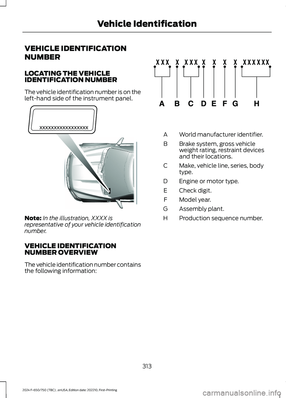
LOCATING THE VEHICLEIDENTIFICATION NUMBER
The vehicle identification number is on theleft-hand side of the instrument panel.
Note:In the illustration, XXXX isrepresentative of your vehicle identificationnumber.
VEHICLE IDENTIFICATIONNUMBER OVERVIEW
The vehicle identification number containsthe following information:
World manufacturer identifier.A
Brake system, gross vehicleweight rating, restraint devicesand their locations.
B
Make, vehicle line, series, bodytype.C
Engine or motor type.D
Check digit.E
Model year.F
Assembly plant.G
Production sequence number.H
313
2024 F-650/750 (TBC) , enUSA, Edition date: 202210, First-PrintingVehicle IdentificationE311767 E142477
Page 328 of 386
Less Cost to Properly Maintain YourVehicle
Ford Protect extended service plan alsooffers a Premium Maintenance Plan thatcovers all scheduled maintenance, andselected wear items. The coverage isprepaid, so you never have to worry aboutthe cost of your vehicle’s maintenance.
Covered maintenance includes:
•Windshield wiper blades.
•Spark plugs.
•The clutch disc (if equipped).
•Brake pads and linings.
•Shock absorbers.
•Struts.
•Engine belts.
•Engine coolant hoses, clamps andO-rings.
•Diesel exhaust fluid replenishment (ifequipped).
•Cabin air filter replacement every20,000 mi (32,000 km) (electricvehicles only).
Interest Free Finance Options
Just a 5% down payment will provide youwith an affordable, no interest, no feepayment program allowing you all thesecurity and benefits Ford Protectextended service plan has to offer whilepaying over time. You are pre-approvedwith no credit check or hassles. To learnmore, call our Ford Protect extendedservice plan specialists at 800-367-3377.
Ford Protect Extended Service PlanP.O. Box 321067Detroit, MI 48232
Ford Protect Extended ServicePlan (CANADA ONLY)
You can get more protection for yourvehicle by purchasing a Ford Protectextended service plan. Ford Protectextended service plan is the only servicecontract backed by Ford Motor Companyof Canada, Limited. Depending on the planyou purchase, Ford Protect extendedservice plan provides benefits such as:
•Rental reimbursement.
•Coverage for certain maintenance andwear items.
•Protection against repair costs afteryour New Vehicle Limited WarrantyCoverage expires.
•Roadside Assistance benefits.
There are several Ford Protect extendedservice plans available in various time,distance and deductible combinations.Each plan is tailored to fit your own drivingneeds, including reimbursement for towingand rental. When you purchase FordProtect extended service plan, you receiveadded peace-of-mind protectionthroughout Canada, the United States andMexico, provided by a network ofparticipating authorized Ford MotorCompany dealers.
Note:Repairs performed outside of Canadaand the United States are not eligible forFord Protect extended service plancoverage.
This information is subject to change. Formore information; visit your local Ford ofCanada dealer or www.ford.ca to find theFord Protect extended service plan that isright for you.
324
2024 F-650/750 (TBC) , enUSA, Edition date: 202210, First-PrintingFord Protect
Page 331 of 386
Scheduled Maintenance Services
Maintenance service adjustments mustconform to specifications contained in thismanual, and those shown on the ImportantEngine Information decal. Perform thefollowing services at scheduled intervalsbecause they essential to the life andperformance of your vehicle. Fordrecommends that you performmaintenance on all designated items toachieve best vehicle operation.
There are three types of maintenanceintervals for general vehicle environments:On-Highway, City and Severe Service. Inall applications, monitoring miles(kilometers) and time and when the engineis due for an oil change determine theactual interval. When the engine oil changeis required before the truck lubricationinterval, perform the lubrication at thesame time in order to reduce your vehicle’stime out of service.
Air Brake Adjustment
WARNING: Failure to maintainproper air brake adjustment can resultin reduction or loss of braking ability.
A qualified service technician, keeping tothe instructions in the service manual,should perform air brake inspection andadjustment or repairs.
Cam Brakes - Automatic SlackAdjusters
WARNING: Do not manually adjustthe automatic slack adjusters to correctexcessive push rod stroke as it may resultin reduced brake effectiveness and avehicle crash. Excessive push rod strokeindicates that a problem exists with theautomatic adjuster, with the installationof the adjuster, or with foundation brakecomponents that manual adjustmentdoes not remedy. Seek service from aqualified facility for excessive push rodstroke.
Inspect standard air brakes equipped withautomatic slack adjusters for proper brakeadjustment as listed in the maintenanceschedule charts.
However, inspect the brakes morefrequently when subjecting them to heavyuse or adverse operating conditions suchas:
•Frequent brake applications while fullyloaded.
•Operation on hilly or mountainousterrain.
•Frequent operation on dirt, gravel ormud.
Some aftermarket brake linings alsorequire more frequent inspections.
Owner Checks and Services
Make sure you perform the following basicmaintenance checks and inspections everymonth or at six-month intervals.
327
2024 F-650/750 (TBC) , enUSA, Edition date: 202210, First-PrintingScheduled Maintenance