bulb FORD F650/750 2024 Owners Manual
[x] Cancel search | Manufacturer: FORD, Model Year: 2024, Model line: F650/750, Model: FORD F650/750 2024Pages: 386, PDF Size: 8.7 MB
Page 8 of 386
Jump Starting the Vehicle........................190
Transporting the Vehicle...........................192
Towing Points...............................................193
Crash and BreakdownInformation
Roadside Assistance..................................194
Automatic Crash Shutoff.........................195
Customer Assistance
Getting the Services You Need..............196
In California (U.S. Only).............................197
The Better Business Bureau (BBB) AutoLine Program (U.S. Only).....................198
Getting Assistance Outside the U.S. andCanada.......................................................199
Ordering Additional Owner's Literature.......................................................................200
Reporting Safety Defects (U.S. Only).......................................................................200
Reporting Safety Defects (Canada Only).........................................................................201
Fuses
Fuse Specification Chart.........................202
Changing a Fuse............................................211
Vehicle Inspection Guide
Vehicle Inspection Information..............213
Maintenance
General Information...................................222
Opening and Closing the Hood.............223
Under Hood Overview - 6.7L Diesel......225
Under Hood Overview - 7.3L...................226
Engine Oil Dipstick - 6.7L Diesel............227
Engine Oil Dipstick - 7.3L..........................227
Engine Oil Check..........................................227
Changing the Engine Oil and Oil Filter........................................................................228
Oil Change Indicator Reset.....................229
Changing the Engine Air Filter - 6.7LDiesel..........................................................230
Changing the Engine Air Filter - 7.3L.....232
Draining the Fuel Filter Water Trap - 6.7LDiesel...........................................................234
Engine Coolant Check - 6.7L Diesel......235
Engine Coolant Check - 7.3L...................238
Automatic Transmission Fluid Check........................................................................243
Brake Fluid Check.......................................245
Power Steering Fluid Check...................246
Changing the 12V Battery........................246
Adjusting the Headlamps.......................248
Washer Fluid Check...................................249
Fuel Filter - 7.3L...........................................249
Checking the Wiper Blades....................249
Changing the Wiper Blades....................250
Removing a Headlamp............................250
Changing a Bulb.........................................250
Changing the Engine-Mounted andDiesel Fuel Conditioner Module FuelFilters - 6.7L Diesel..................................251
Electrical System Inspection..................254
Air Induction System Inspection...........255
Exhaust System Inspection....................255
Brake System Inspection.........................256
Axle Inspection............................................259
Steering System Inspection...................259
Suspension System Inspection............260
Frame and Tow Hook Inspection.........260
Rear Axle Fluid Check...............................260
Spring U-Bolt Check...................................261
Vehicle Care
General Information..................................262
Cleaning Products......................................262
Cleaning the Exterior.................................263
Waxing............................................................264
Cleaning the Engine..................................264
Cleaning the Windows and Wiper Blades........................................................................265
4
2024 F-650/750 (TBC) , enUSA, Edition date: 202210, First-PrintingTable of Contents
Page 9 of 386
Cleaning the Interior..................................265
Cleaning the Instrument Panel andInstrument Cluster Lens......................266
Repairing Minor Paint Damage.............266
Cleaning the Wheels.................................266
Vehicle Storage............................................267
Wheels and Tires
Tire Care.........................................................269
Using Snow Chains....................................287
Changing a Road Wheel..........................287
Technical Specifications.........................289
Capacities and Specifications
Engine Specifications - 6.7L Diesel.......291
Engine Specifications - 7.3L....................292
Motorcraft Parts - 6.7L Diesel................293
Motorcraft Parts - 7.3L..............................295
Bulb Specification Chart.........................296
Engine Oil Capacity and Specification -6.7L Diesel.................................................296
Engine Oil Capacity and Specification -7.3L...............................................................299
Cooling System Capacity andSpecification - 6.7L Diesel...................301
Cooling System Capacity andSpecification - 7.3L................................302
Fuel Tank Capacity - Diesel....................303
Fuel Tank Capacity - Gasoline..............304
Air Conditioning System Capacity andSpecification - 6.7L Diesel..................305
Air Conditioning System Capacity andSpecification - 7.3L................................306
Washer Fluid Specification....................306
Diesel Exhaust Fluid Capacity andSpecification............................................307
Automatic Transmission Fluid Capacityand Specification - Diesel...................307
Automatic Transmission Fluid Capacityand Specification - Gasoline.............308
Brake Fluid Specification........................309
Rear Axle Fluid Capacity andSpecification - Diesel...........................309
Rear Axle Fluid Capacity andSpecification - Gasoline.........................311
Hydraulic Power Steering Fluid Capacityand Specification.....................................312
Vehicle Identification
Vehicle Identification Number................313
Connected Vehicle
Connected Vehicle Requirements.........314
Connected Vehicle Limitations..............314
Connecting the Vehicle to a MobileNetwork.......................................................314
Connected Vehicle – Troubleshooting.........................................................................314
Audio System
General Information...................................315
Audio Unit.......................................................315
Connecting a Bluetooth® Device..........318
Streaming Bluetooth Audio.....................318
Playing Media From a USB Device........318
Audio Input Jack...........................................319
USB Port........................................................320
Using Voice Recognition..........................320
Accessories
Auxiliary Switches.......................................321
Ford Protect
Ford Protect..................................................323
Scheduled Maintenance
General Maintenance Information.......325
Normal Scheduled Maintenance.........330
Special Operating Conditions ScheduledMaintenance............................................335
5
2024 F-650/750 (TBC) , enUSA, Edition date: 202210, First-PrintingTable of Contents
Page 71 of 386
Diesel Exhaust Fluid Gauge
Indicates the fluid level in the dieselexhaust fluid (DEF) tank.
Voltmeter
Displays electrical system voltage.
WARNING LAMPS AND
INDICATORS
The following warning lamps andindicators alert you to a vehicle conditionthat may become serious. Some lampsilluminate when you start your vehicle tomake sure they work. If any lamps remainon after starting your vehicle, refer to therespective system warning lamp for furtherinformation.
Note:Some warning indicators appear inthe information display and operate thesame as a warning lamp but do notilluminate when you start your vehicle.
Anti-Lock Braking System
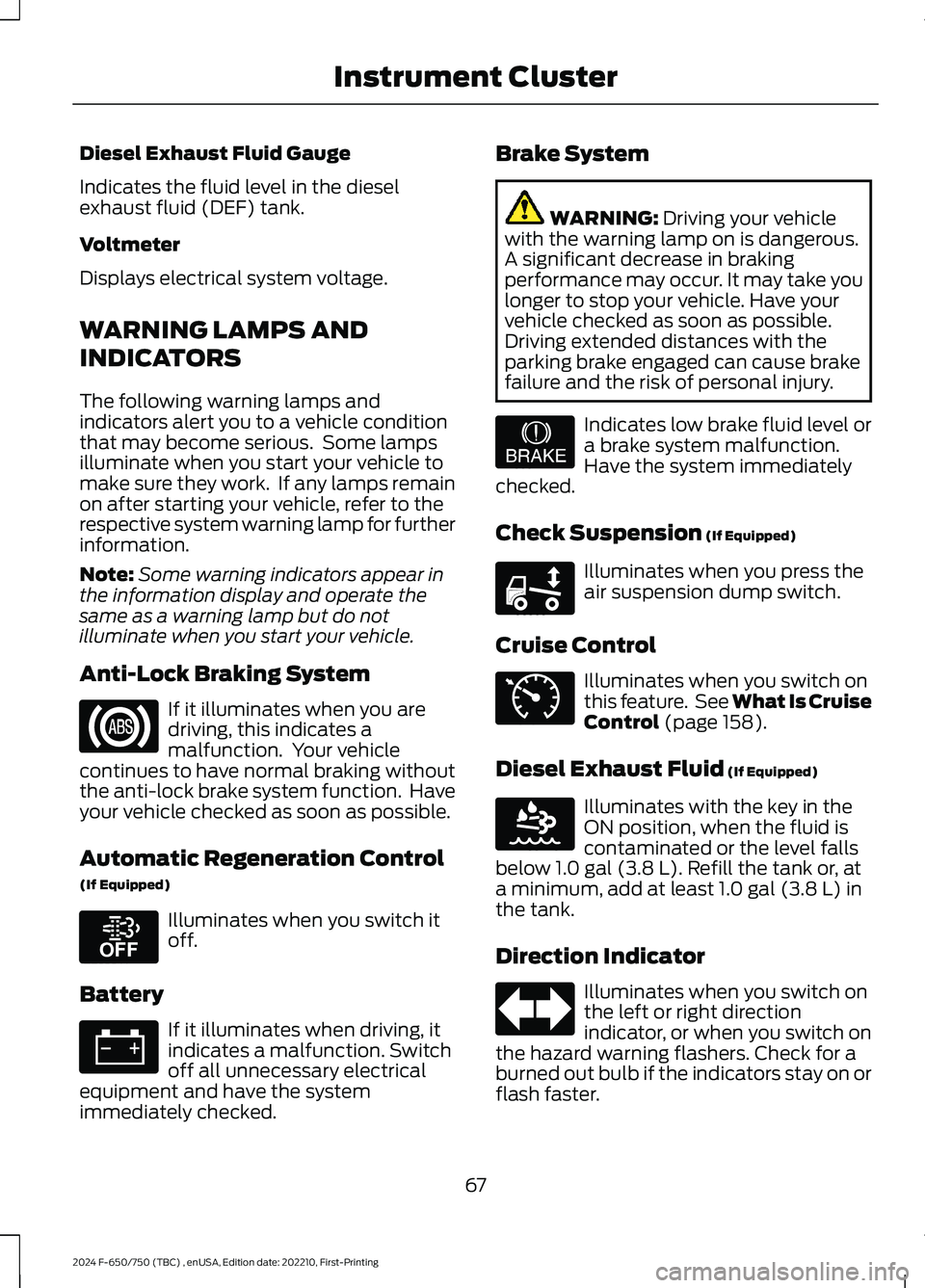
If it illuminates when you aredriving, this indicates amalfunction. Your vehiclecontinues to have normal braking withoutthe anti-lock brake system function. Haveyour vehicle checked as soon as possible.
Automatic Regeneration Control
(If Equipped)
Illuminates when you switch itoff.
Battery
If it illuminates when driving, itindicates a malfunction. Switchoff all unnecessary electricalequipment and have the systemimmediately checked.
Brake System
WARNING: Driving your vehiclewith the warning lamp on is dangerous.A significant decrease in brakingperformance may occur. It may take youlonger to stop your vehicle. Have yourvehicle checked as soon as possible.Driving extended distances with theparking brake engaged can cause brakefailure and the risk of personal injury.
Indicates low brake fluid level ora brake system malfunction.Have the system immediatelychecked.
Check Suspension (If Equipped)
Illuminates when you press theair suspension dump switch.
Cruise Control
Illuminates when you switch onthis feature. See What Is CruiseControl (page 158).
Diesel Exhaust Fluid (If Equipped)
Illuminates with the key in theON position, when the fluid iscontaminated or the level fallsbelow 1.0 gal (3.8 L). Refill the tank or, ata minimum, add at least 1.0 gal (3.8 L) inthe tank.
Direction Indicator
Illuminates when you switch onthe left or right directionindicator, or when you switch onthe hazard warning flashers. Check for aburned out bulb if the indicators stay on orflash faster.
67
2024 F-650/750 (TBC) , enUSA, Edition date: 202210, First-PrintingInstrument ClusterE67020 E208811 E67021 E209041 E208808 E71340 E163176 E67018
Page 73 of 386
Powertrain Malfunction/ReducedPower/Electronic Throttle Control
(If Equipped)
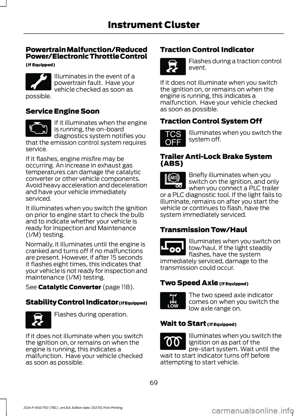
Illuminates in the event of apowertrain fault. Have yourvehicle checked as soon aspossible.
Service Engine Soon
If it illuminates when the engineis running, the on-boarddiagnostics system notifies youthat the emission control system requiresservice.
If it flashes, engine misfire may beoccurring. An increase in exhaust gastemperatures can damage the catalyticconverter or other vehicle components.Avoid heavy acceleration and decelerationand have your vehicle immediatelyserviced.
It illuminates when you switch the ignitionon prior to engine start to check the bulband to indicate whether your vehicle isready for Inspection and Maintenance(I/M) testing.
Normally, it illuminates until the engine iscranked and turns off if no malfunctionsare present. However, if after 15 secondsit flashes eight times, this indicates thatyour vehicle is not ready for inspection andmaintenance (I/M) testing.
See Catalytic Converter (page 118).
Stability Control Indicator (If Equipped)
Flashes during operation.
If it does not illuminate when you switchthe ignition on, or remains on when theengine is running, this indicates amalfunction. Have your vehicle checkedas soon as possible.
Traction Control Indicator
Flashes during a traction controlevent.
If it does not illuminate when you switchthe ignition on, or remains on when theengine is running, this indicates amalfunction. Have your vehicle checkedas soon as possible.
Traction Control System Off
Illuminates when you switch thesystem off.
Trailer Anti-Lock Brake System(ABS)
Briefly illuminates when youswitch on the ignition, and onlywhen you connect a PLC traileror a PLC diagnostic tool. If the light fails toilluminate, remains on after you start thevehicle or continues to flash, have thesystem immediately serviced.
Transmission Tow/Haul
Illuminates when you switch ontow/haul. If the light steadilyflashes, have the systemimmediately serviced, damage to thetransmission could occur.
Two Speed Axle (If Equipped)
The two speed axle indicatorcomes on when you switch thelow axle range on.
Wait to Start (If Equipped)
Illuminates when you switch theignition on as part of thepre-start system. Wait until thewait to start indicator turns off beforeattempting to start vehicle.
69
2024 F-650/750 (TBC) , enUSA, Edition date: 202210, First-PrintingInstrument Cluster E67028 E138639 E138639 E194301 E209040 E246592 E208809
Page 123 of 386
Illumination of the service engine soonindicator, charging system warning light orthe temperature warning light, fluid leaks,strange odors, smoke or loss of enginepower could indicate that the emissioncontrol system is not working properly.
An improperly operating or damagedexhaust system may allow exhaust toenter the vehicle. Have a damaged orimproperly operating exhaust systeminspected and repaired immediately.
Do not make any unauthorized changes toyour vehicle or engine. By law, vehicleowners and anyone who manufactures,repairs, services, sells, leases, tradesvehicles, or supervises a fleet of vehiclesare not permitted to intentionally removean emission control device or prevent itfrom working. Information about yourvehicle’s emission system is on the VehicleEmission Control Information Decallocated on or near the engine. This decalalso lists engine displacement.
Please consult your warranty informationfor complete details.
On-Board Diagnostics (OBD-II)
Your vehicle has a computer known as theon-board diagnostics system (OBD-II) thatmonitors the engine’s emission controlsystem. The system protects theenvironment by making sure that yourvehicle continues to meet governmentemission standards. The OBD-II systemalso assists a service technician in properlyservicing your vehicle.
When the service engine soonindicator illuminates, the OBD-IIsystem has detected amalfunction. Temporary malfunctions maycause the service engine soon indicator toilluminate. Examples are:
1.Your vehicle has run out of fuel—theengine may misfire or run poorly.
2.Poor fuel quality or water in thefuel—the engine may misfire or runpoorly.
3.The fuel fill inlet may not have closedproperly. See Refueling (page 112).
4.Driving through deep water—theelectrical system may be wet.
You can correct these temporarymalfunctions by filling the fuel tank withgood quality fuel, properly closing the fuelfill inlet or letting the electrical system dryout. After three driving cycles without theseor any other temporary malfunctionspresent, the service engine soon indicatorshould stay off the next time you start theengine. A driving cycle consists of a coldengine startup followed by mixed city andhighway driving. No additional vehicleservice is required.
If the service engine soon indicator remainson, have your vehicle serviced at the firstavailable opportunity. Although somemalfunctions detected by the OBD-II maynot have symptoms that are apparent,continued driving with the service enginesoon indicator on can result in increasedemissions, lower fuel economy, reducedengine and transmission smoothness andlead to more costly repairs.
Readiness for Inspection andMaintenance (I/M) Testing
Some state and provincial and localgovernments may haveInspection/Maintenance (I/M) programsto inspect the emission control equipmenton your vehicle. Failure to pass thisinspection could prevent you from gettinga vehicle registration.
If the service engine soonindicator is on or the bulb doesnot work, your vehicle may needservice. See On-Board Diagnostics.
119
2024 F-650/750 (TBC) , enUSA, Edition date: 202210, First-PrintingEngine Emission ControlE67028 E67028
Page 124 of 386
Your vehicle may not pass the I/M test ifthe service engine soon indicator is on ornot working properly (bulb is burned out),or if the OBD-II system has determinedthat some of the emission control systemshave not been properly checked. In thiscase, the vehicle is not ready for I/Mtesting.
If the vehicle’s engine or transmission hasjust been serviced, or the battery hasrecently run down or been replaced, theOBD-II system may indicate that thevehicle is not ready for I/M testing. Todetermine if the vehicle is ready for I/Mtesting, turn the ignition key to the onposition for 15 seconds without crankingthe engine. If the service engine soonindicator blinks eight times, it means thatthe vehicle is not ready for I/M testing; ifthe service engine soon indicator stays onsolid, it means that your vehicle is readyfor I/M testing.
The OBD-II system checks the emissioncontrol system during normal driving. Acomplete check may take several days.
If the vehicle is not ready for I/M testing,you can perform the following driving cycleconsisting of mixed city and highwaydriving:
1.15 minutes of steady driving on anexpressway or highway followed by 20minutes of stop-and-go driving with atleast four 30-second idle periods.
2.Allow your vehicle to sit for at leasteight hours with the ignition off. Then,start the vehicle and complete theabove driving cycle. The vehicle mustwarm up to its normal operatingtemperature. Once started, do not turnoff the vehicle until the above drivingcycle is complete.
If the vehicle is still not ready for I/Mtesting, you need to repeat the abovedriving cycle.
SELECTIVE CATALYTIC
REDUCTANT SYSTEM - DIESEL
Your vehicle may have a selective catalyticreduction system. This system helpsreduce emission levels of oxides ofnitrogen from the exhaust system. Thesystem automatically injects dieselexhaust fluid into the exhaust system toenable correct selective catalytic reductionsystem function.
Note:Selective catalytic reduction systemsare not fitted to vehicles in markets whereonly high-sulfur diesel fuel is available.
Diesel Exhaust Fluid Level
In order for the system to operate correctlyyou must maintain the diesel exhaust fluidlevel.
The system has a sensor to monitor fluidlevel and quality/concentration. A warningmessage appears in the informationdisplay when the diesel exhaust fluid levelis low. If a warning message appears, refillthe diesel exhaust fluid tank as soon aspossible. See Information Messages(page 75).
Filling the Diesel Exhaust FluidTank
WARNING: Keep diesel exhaustfluid out of reach of children. Avoidcontact with skin, eyes or clothing. Incase of contact with your eyes, flushimmediately with water and get promptmedical attention. In case of contactwith your skin, clean immediately withsoap and water. If you swallow anydiesel exhaust fluid, drink plenty ofwater, call a physician immediately.
120
2024 F-650/750 (TBC) , enUSA, Edition date: 202210, First-PrintingEngine Emission Control
Page 252 of 386
the driver that battery protection actionsare active. These messages are only fornotification that an action is taking place,and not intended to indicate an electricalproblem or that the battery requiresreplacement.
Electrical accessory installation
To ensure proper operation of the BMS,any electrical devices that are added tothe vehicle should not have their groundconnection made directly at the negativebattery post. A connection at the negativebattery post can cause inaccuratemeasurements of the battery conditionand potential incorrect system operation.
Note:Electrical or electronic accessoriesadded to the vehicle by the dealer or theowner may adversely affect batteryperformance and durability, and may alsoaffect the performance of other electricalsystems in the vehicle.
When a battery replacement is required,the battery should only be replaced witha Ford recommended replacement batterywhich matches the electrical requirementsof the vehicle. After battery replacement,or in some cases after charging the batterywith the external charger, the BMS requireseight hours of vehicle sleep time (key offwith doors closed) to relearn the newbattery state of charge. Prior to relearningthe state of charge, the BMS may disableelectrical features (to protect the battery)earlier than normal.
ADJUSTING THE HEADLAMPS
Vertical Aim Adjustment
The headlamps on your vehicle areproperly aimed at the assembly plant. Ifyour vehicle has been in an accident, thealignment of your headlamps should bechecked by your authorized dealer.
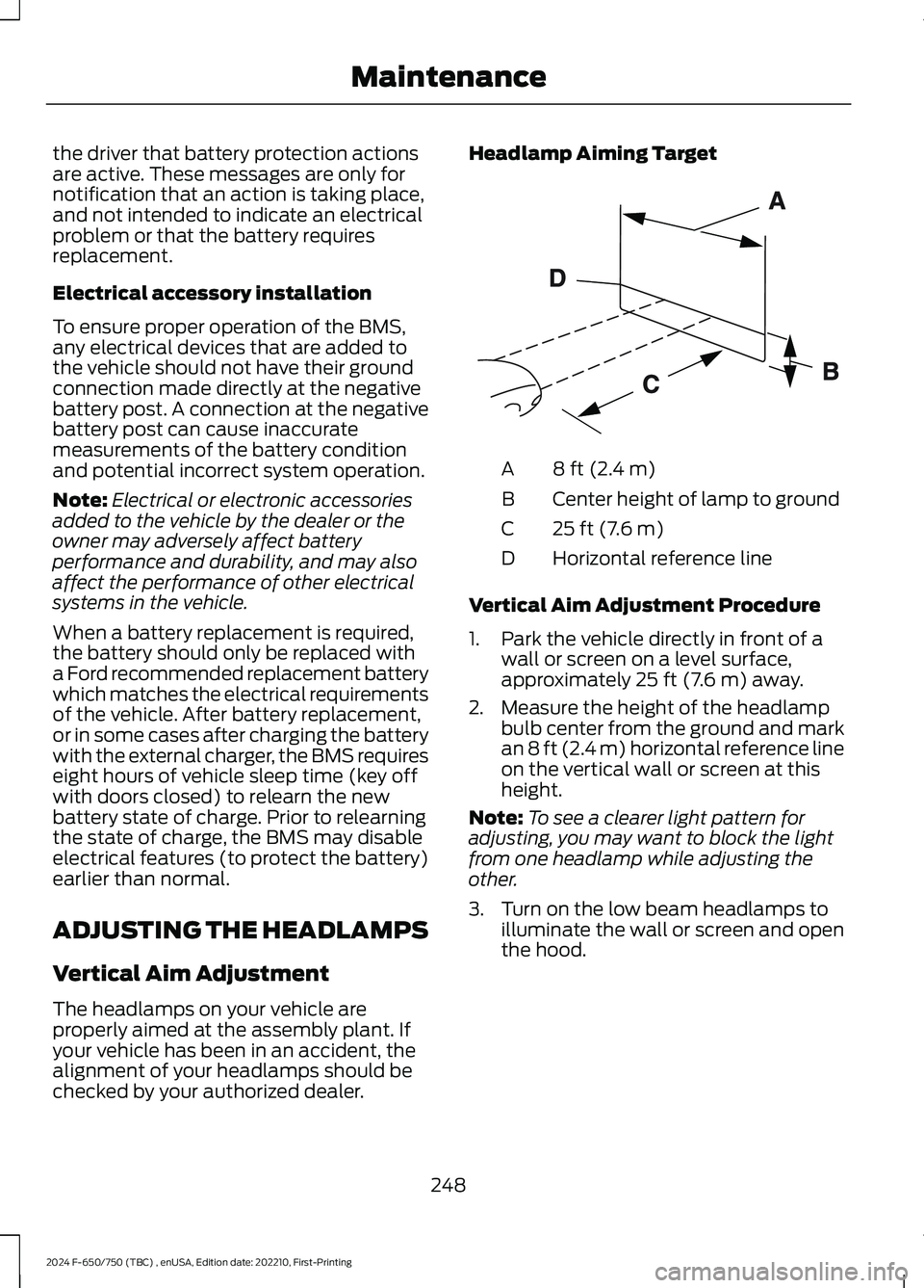
Headlamp Aiming Target
8 ft (2.4 m)A
Center height of lamp to groundB
25 ft (7.6 m)C
Horizontal reference lineD
Vertical Aim Adjustment Procedure
1.Park the vehicle directly in front of awall or screen on a level surface,approximately 25 ft (7.6 m) away.
2.Measure the height of the headlampbulb center from the ground and markan 8 ft (2.4 m) horizontal reference lineon the vertical wall or screen at thisheight.
Note:To see a clearer light pattern foradjusting, you may want to block the lightfrom one headlamp while adjusting theother.
3.Turn on the low beam headlamps toilluminate the wall or screen and openthe hood.
248
2024 F-650/750 (TBC) , enUSA, Edition date: 202210, First-PrintingMaintenanceE142592
Page 254 of 386
Run the tip of your fingers over the edge ofthe blade to check for roughness.
Clean the wiper blades with washer fluidor water applied with a soft sponge orcloth.
CHANGING THE WIPER
BLADES
You can manually move the wiper armswhen the ignition is off. This allows for easeof blade replacement and cleaning underthe blades.
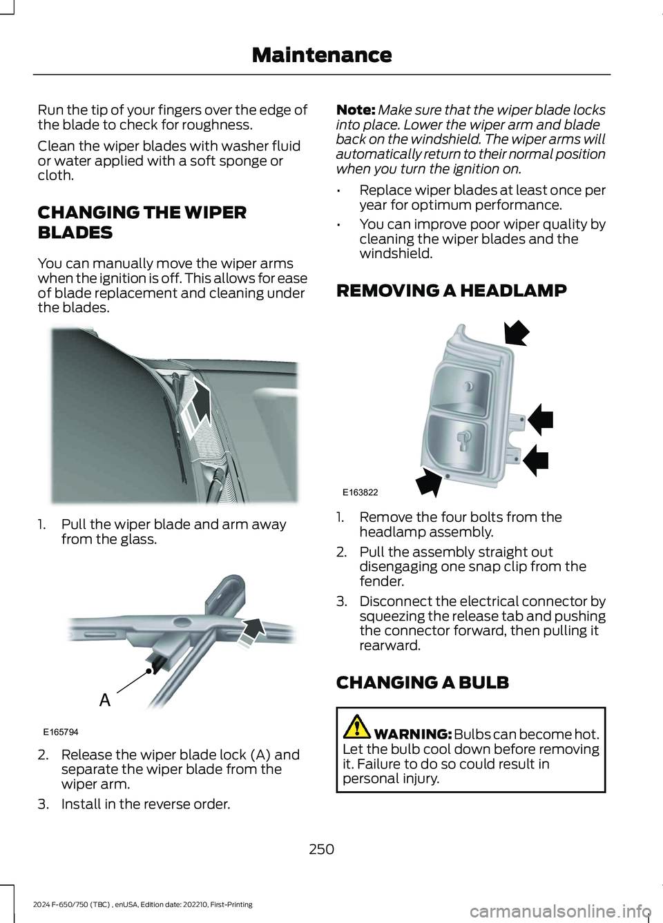
1.Pull the wiper blade and arm awayfrom the glass.
2.Release the wiper blade lock (A) andseparate the wiper blade from thewiper arm.
3.Install in the reverse order.
Note:Make sure that the wiper blade locksinto place. Lower the wiper arm and bladeback on the windshield. The wiper arms willautomatically return to their normal positionwhen you turn the ignition on.
•Replace wiper blades at least once peryear for optimum performance.
•You can improve poor wiper quality bycleaning the wiper blades and thewindshield.
REMOVING A HEADLAMP
1.Remove the four bolts from theheadlamp assembly.
2.Pull the assembly straight outdisengaging one snap clip from thefender.
3.Disconnect the electrical connector bysqueezing the release tab and pushingthe connector forward, then pulling itrearward.
CHANGING A BULB
WARNING: Bulbs can become hot.Let the bulb cool down before removingit. Failure to do so could result inpersonal injury.
250
2024 F-650/750 (TBC) , enUSA, Edition date: 202210, First-PrintingMaintenanceE165804 AE165794 E163822
Page 255 of 386
Headlamp bulbs must be marked with anauthorized D.O.T. marking for NorthAmerica to make sure they have the properlamp performance, light brightness, lightpattern and safe visibility.
Install in the reverse order unless otherwisestated.
Headlamp Bulbs
1.Switch all of the lamps and the ignitionoff.
2.Remove the headlamp. SeeRemoving a Headlamp (page 250).
3.Release the clip and remove the bulb.
Note:Do not touch the bulb glass.
Note:If the bulb is accidentally touched, itshould be cleaned with rubbing alcoholbefore being used.
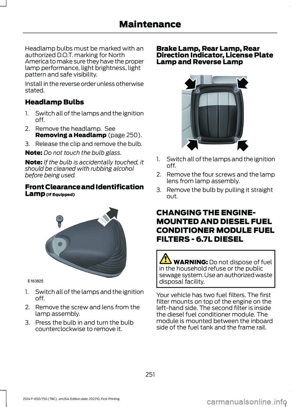
Front Clearance and IdentificationLamp (If Equipped)
1.Switch all of the lamps and the ignitionoff.
2.Remove the screw and lens from thelamp assembly.
3.Press the bulb in and turn the bulbcounterclockwise to remove it.
Brake Lamp, Rear Lamp, RearDirection Indicator, License PlateLamp and Reverse Lamp
1.Switch all of the lamps and the ignitionoff.
2.Remove the four screws and the lamplens from lamp assembly.
3.Remove the bulb by pulling it straightout.
CHANGING THE ENGINE-
MOUNTED AND DIESEL FUEL
CONDITIONER MODULE FUEL
FILTERS - 6.7L DIESEL
WARNING: Do not dispose of fuelin the household refuse or the publicsewage system. Use an authorized wastedisposal facility.
Your vehicle has two fuel filters. The firstfilter mounts on top of the engine on theleft-hand side. The second filter is insidethe diesel fuel conditioner module. Themodule is mounted between the inboardside of the fuel tank and the frame rail.
251
2024 F-650/750 (TBC) , enUSA, Edition date: 202210, First-PrintingMaintenanceE163825 E163828
Page 300 of 386
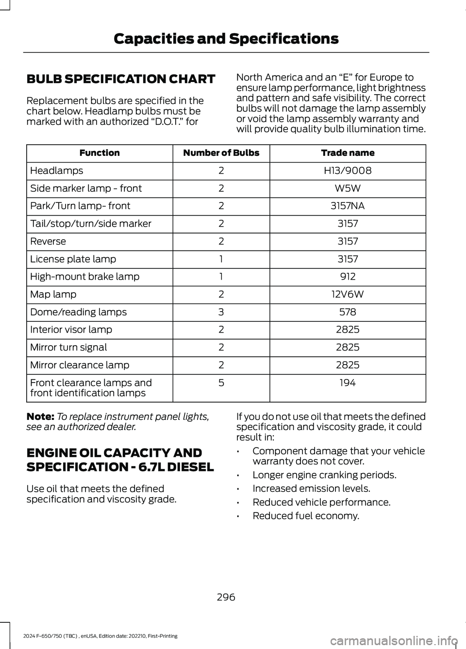
BULB SPECIFICATION CHART
Replacement bulbs are specified in thechart below. Headlamp bulbs must bemarked with an authorized “D.O.T.” for
North America and an “E” for Europe toensure lamp performance, light brightnessand pattern and safe visibility. The correctbulbs will not damage the lamp assemblyor void the lamp assembly warranty andwill provide quality bulb illumination time.
Trade nameNumber of BulbsFunction
H13/90082Headlamps
W5W2Side marker lamp - front
3157NA2Park/Turn lamp- front
31572Tail/stop/turn/side marker
31572Reverse
31571License plate lamp
9121High-mount brake lamp
12V6W2Map lamp
5783Dome/reading lamps
28252Interior visor lamp
28252Mirror turn signal
28252Mirror clearance lamp
1945Front clearance lamps andfront identification lamps
Note:To replace instrument panel lights,see an authorized dealer.
ENGINE OIL CAPACITY AND
SPECIFICATION - 6.7L DIESEL
Use oil that meets the definedspecification and viscosity grade.
If you do not use oil that meets the definedspecification and viscosity grade, it couldresult in:
•Component damage that your vehiclewarranty does not cover.
•Longer engine cranking periods.
•Increased emission levels.
•Reduced vehicle performance.
•Reduced fuel economy.
296
2024 F-650/750 (TBC) , enUSA, Edition date: 202210, First-PrintingCapacities and Specifications