FORD F750 2002 10.G Owners Manual
Manufacturer: FORD, Model Year: 2002, Model line: F750, Model: FORD F750 2002 10.GPages: 256, PDF Size: 1.75 MB
Page 211 of 256
5. The lubricant level should be up to the bottom of the filler plug
opening.
6. If necessary, add enough lubricant through the filler plug opening so
that the lubricant level is at the bottom of the opening.
7. Clean and install the filler plug securely.
Drain and refill your rear axle lubricant using the following procedure:
1. Drain the rear axle while the lubricant is warm.
2. Park the vehicle on level ground.
3. Set the parking brake and shift into N (Neutral) (automatic
transmission) or 1 (First) (manual transmission) and turn the engine off.
4. Clean any dirt from around the rear axle filler and drain plugs.
5. Remove the filler and drain plugs and drain the lubricant into a
suitable container. Dispose all used automotive fluids in a responsible
manner following your local authorized standards.
6. Clean and install the drain plug securely.
7. Add enough lubricant through the filler plug opening so that the
lubricant level is up to the bottom of the opening.
8. Clean and install the filler plug securely.
AIR FILTER
When to service
Your vehicle is equipped with an air filter restriction gauge to determine
when to replace the air filter element. It is not possible to determine the
need for service by visually inspecting the air filter.
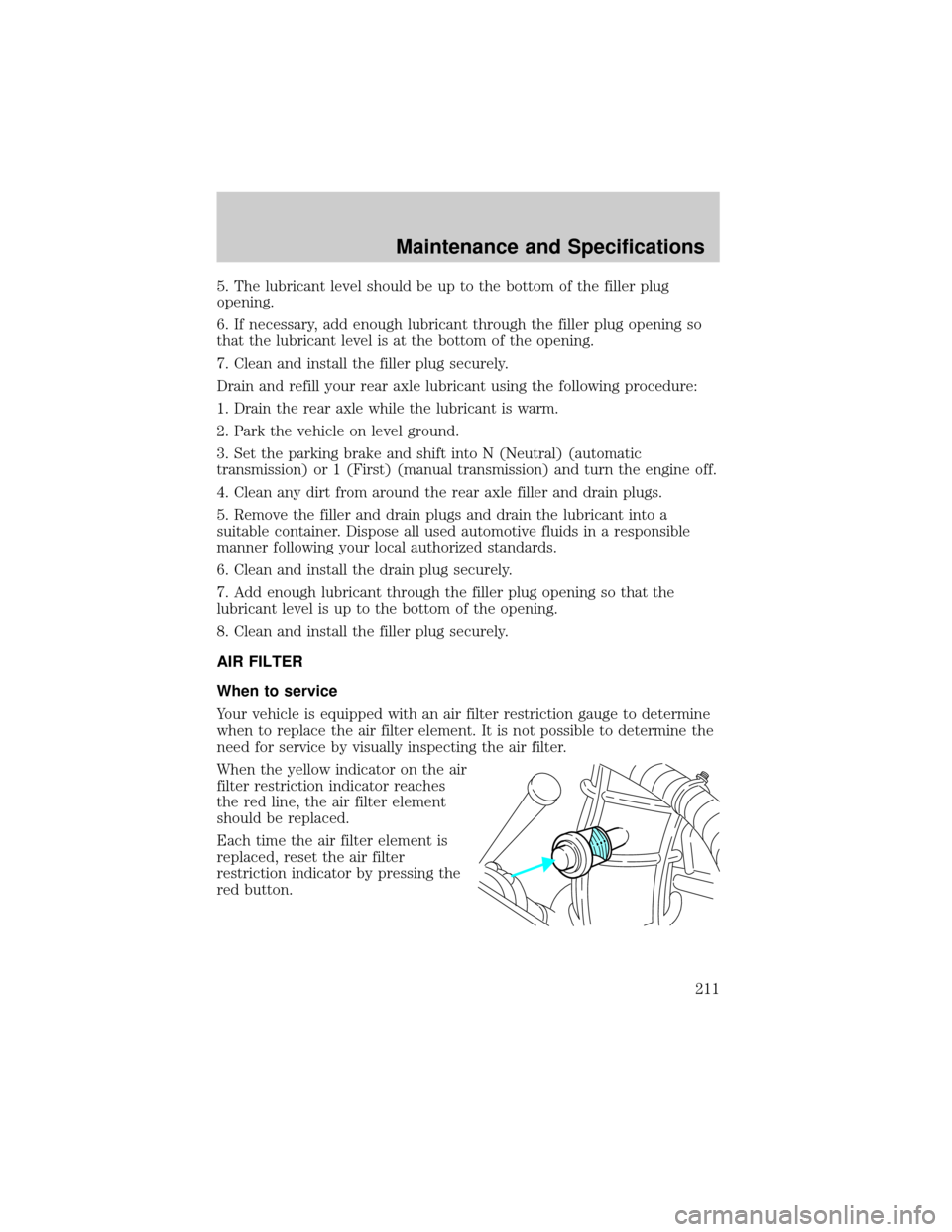
When the yellow indicator on the air
filter restriction indicator reaches
the red line, the air filter element
should be replaced.
Each time the air filter element is
replaced, reset the air filter
restriction indicator by pressing the
red button.
Maintenance and Specifications
211
Page 212 of 256
Servicing the air filter
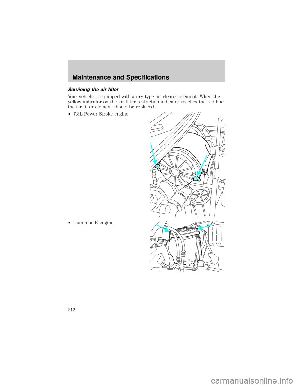
Your vehicle is equipped with a dry-type air cleaner element. When the
yellow indicator on the air filter restriction indicator reaches the red line
the air filter element should be replaced.
²7.3L Power Stroke engine
²Cummins B engine
Maintenance and Specifications
212
Page 213 of 256
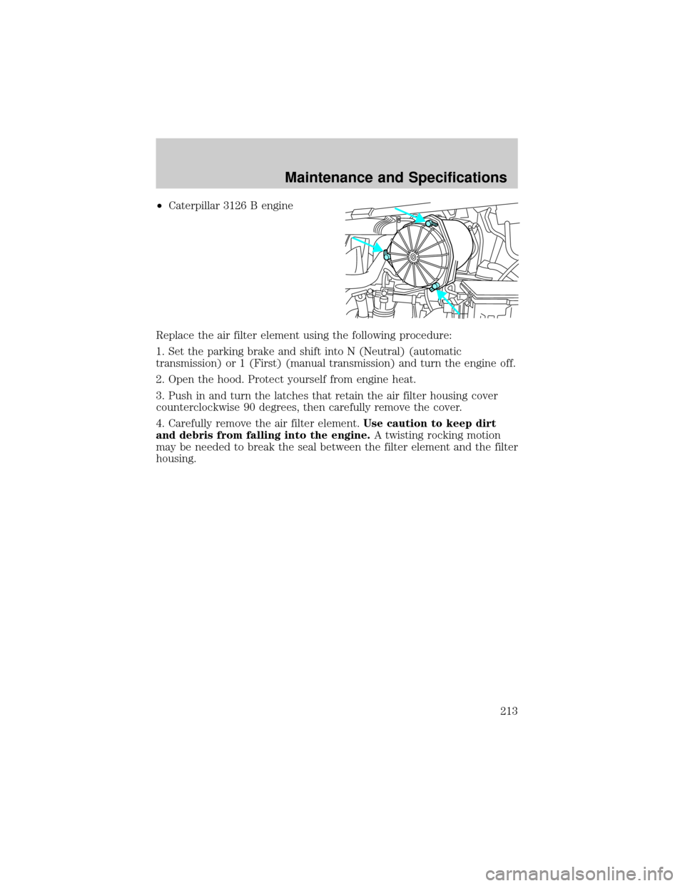
²Caterpillar 3126 B engine
Replace the air filter element using the following procedure:
1. Set the parking brake and shift into N (Neutral) (automatic
transmission) or 1 (First) (manual transmission) and turn the engine off.
2. Open the hood. Protect yourself from engine heat.
3. Push in and turn the latches that retain the air filter housing cover
counterclockwise 90 degrees, then carefully remove the cover.
4. Carefully remove the air filter element.Use caution to keep dirt
and debris from falling into the engine.A twisting rocking motion
may be needed to break the seal between the filter element and the filter
housing.
Maintenance and Specifications
213
Page 214 of 256
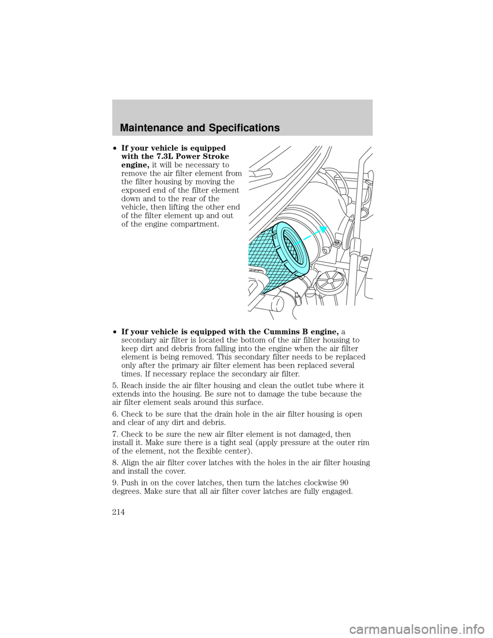
²If your vehicle is equipped
with the 7.3L Power Stroke
engine,it will be necessary to
remove the air filter element from
the filter housing by moving the
exposed end of the filter element
down and to the rear of the
vehicle, then lifting the other end
of the filter element up and out
of the engine compartment.
²If your vehicle is equipped with the Cummins B engine,a
secondary air filter is located the bottom of the air filter housing to
keep dirt and debris from falling into the engine when the air filter
element is being removed. This secondary filter needs to be replaced
only after the primary air filter element has been replaced several
times. If necessary replace the secondary air filter.
5. Reach inside the air filter housing and clean the outlet tube where it
extends into the housing. Be sure not to damage the tube because the
air filter element seals around this surface.
6. Check to be sure that the drain hole in the air filter housing is open
and clear of any dirt and debris.
7. Check to be sure the new air filter element is not damaged, then
install it. Make sure there is a tight seal (apply pressure at the outer rim
of the element, not the flexible center).
8. Align the air filter cover latches with the holes in the air filter housing
and install the cover.
9. Push in on the cover latches, then turn the latches clockwise 90
degrees. Make sure that all air filter cover latches are fully engaged.
Maintenance and Specifications
214
Page 215 of 256
10. Reset the air filter restriction indicator.
11. Inspect the air induction system for loose fitting, damaged or missing
components and repair as necessary.
SERVICING YOUR WHEELS AND TIRES
Wheel assembly
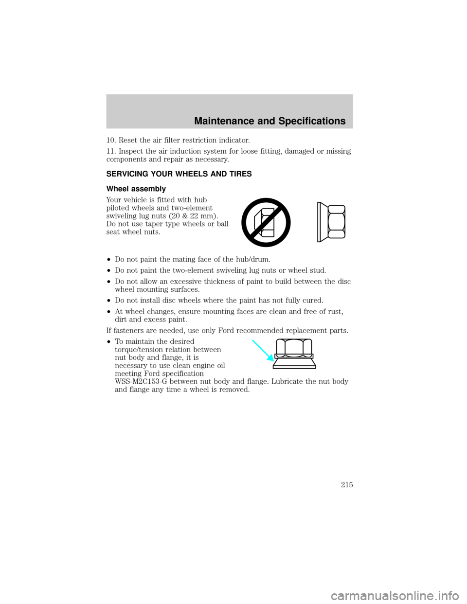
Your vehicle is fitted with hub
piloted wheels and two-element
swiveling lug nuts (20 & 22 mm).
Do not use taper type wheels or ball
seat wheel nuts.
²Do not paint the mating face of the hub/drum.
²Do not paint the two-element swiveling lug nuts or wheel stud.
²Do not allow an excessive thickness of paint to build between the disc
wheel mounting surfaces.
²Do not install disc wheels where the paint has not fully cured.
²At wheel changes, ensure mounting faces are clean and free of rust,
dirt and excess paint.
If fasteners are needed, use only Ford recommended replacement parts.
²To maintain the desired
torque/tension relation between
nut body and flange, it is
necessary to use clean engine oil
meeting Ford specification
WSS-M2C153-G between nut body and flange. Lubricate the nut body
and flange any time a wheel is removed.
Maintenance and Specifications
215
Page 216 of 256
The M20 & M22 wheel nuts are right-hand threads. Refer to the
following chart for approved wheel lug nut torque.
Wheel type Bolt size Wheel nut torque
10-hole disc 285.75
mm bolt circleM22 (22 by 1.5 mm) 610-677 Nm (450-500
lb-ft)
8-hole disc 19.5x6.75
mm bolt circleM20 (20 by 1.5 mm) 610-677 Nm (450-500
lb-ft)
The disc wheel nuts on your vehicle were tightened before delivery.
Recheck torque of nuts at 160 km (100 miles) and 800 km (500 miles) of
new vehicle operation or any time a wheel is removed. Reset to
recommended torque levels.
Tires are one of the weaker weight carrying components of the
vehicle. Do not overload the vehicle beyond safe load carrying
capacity.
Avoid hammering rim with steel hammers.
Never run the engine with one wheel off the ground.
Failure to retighten wheel lug nuts as required could allow the
wheel to come off while the vehicle is in motion, possibly causing
loss of vehicle control and collision. Loose wheel studs may also cause
shimmy and vibration.
Use of aftermarket wheel assemblies is not recommended; they
may be incompatible with your vehicle and may result in
equipment failure and possible injury. Replacement with used wheels is
not advised; they may have been treated harshly or have high mileage
and could fail without warning.
Maintenance and Specifications
216
Page 217 of 256
A wheel or tire of the wrong size or type may adversely affect
such things as load carrying capacity, wheel and bearing life,
brake cooling, speedometer/odometer calibration, stopping ability,
headlight aim, bumper height, vehicle ground clearance and tire or tire
chain clearance to the body and chassis.
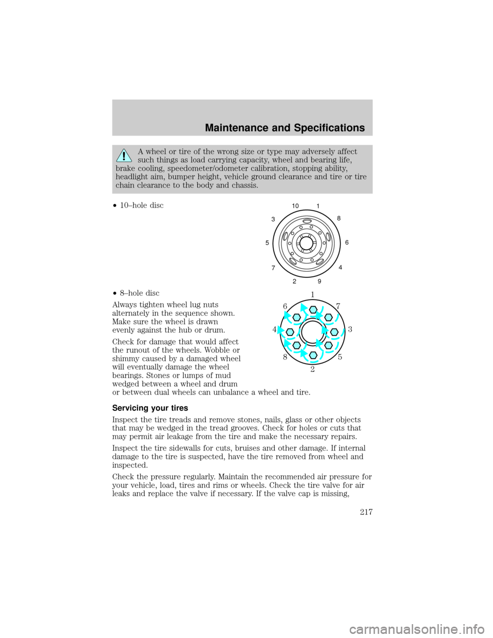
²10±hole disc
²8±hole disc
Always tighten wheel lug nuts
alternately in the sequence shown.
Make sure the wheel is drawn
evenly against the hub or drum.
Check for damage that would affect
the runout of the wheels. Wobble or
shimmy caused by a damaged wheel
will eventually damage the wheel
bearings. Stones or lumps of mud
wedged between a wheel and drum
or between dual wheels can unbalance a wheel and tire.
Servicing your tires
Inspect the tire treads and remove stones, nails, glass or other objects
that may be wedged in the tread grooves. Check for holes or cuts that
may permit air leakage from the tire and make the necessary repairs.
Inspect the tire sidewalls for cuts, bruises and other damage. If internal
damage to the tire is suspected, have the tire removed from wheel and
inspected.
Check the pressure regularly. Maintain the recommended air pressure for
your vehicle, load, tires and rims or wheels. Check the tire valve for air
leaks and replace the valve if necessary. If the valve cap is missing,
5310
1
8
6
4
9 2 7
1
3 4
27 6
5 8
Maintenance and Specifications
217
Page 218 of 256
install a new cap. Refer toTire/Wheel Rim Selection and Inflation
Pressuresor theVehicle Certification Labelin this chapter.
An inflated tire and rim can be very dangerous if improperly
used, serviced or maintained. To avoid serious injury, never
attempt to re-inflate a tire which has been run flat or seriously
under-inflated without first removing the tire from the wheel assembly
for inspection. Do not attempt to add air to tires or replace tires or
wheels without first taking precautions to protect persons and
property.
Refer to the Ford Service Manual or the regulations of the Occupational
Safety and Health Administration (OSHA) for appropriate procedures
and cautions.
Tire inflation pressure must not exceed the recommendations of
the axle, tire and/or wheel rim manufacturer for the specific
load, speed and application. The inflation pressures on the tire sidewall
do not take the wheel rim capabilities into consideration.
Never use a rim of different manufacture or any different size or
type than original rims.
Try to replace tires in pairs on the same axle shaft. Tires larger or
smaller than originally installed may affect the accuracy of the
speedometer. Consult your dealer about the need to change the switch
setting on the back of the speedometer.
Front wheel alignment
If abnormal tire wear or ride and handling characteristics such as vehicle
lead or wander are experienced with properly inflated tires, the front
end alignment should be checked.
Wheel bearing care
Front and rear wheel bearings are adjustable to correct for bearing and
spindle wear. Long bearing life depends upon proper adjustment and
correct lubrication. If bearings are adjusted too tightly (preloaded) they
will overheat and wear rapidly. Loose adjustment will cause pounding
and will contribute to uneven tire wear, steering difficulties and
inefficient brake operation.
Maintenance and Specifications
218
Page 219 of 256
Refer to the Ford Service Manual applicable to your vehicle for proper
tightening procedures and torque specifications.
Periodically check the oil level on oil filled front bearing hubs. If
necessary, add oil through the filler plug so the oil level is between the
ADD and FULL marks indicated on the hub. Do not overfill. Overfilling
can result in oil on brake linings.
Refer to your Scheduled Maintenance Guide for fluid level checks and
change intervals for the front hubs.
Your front hubs may be filled with an optional synthetic fluid which
allows use of the extended service intervals. A green colored filler plug
identifies use of the synthetic fluid.
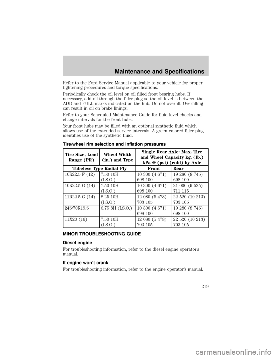
Tire/wheel rim selection and inflation pressures
Tire Size, Load
Range (PR)Wheel Width
(in.) and TypeSingle Rear Axle: Max. Tire
and Wheel Capacity kg. (lb.)
kPa @ (psi) (cold) by Axle
Tubeless Type Radial Ply Front Rear
10R22.5 F (12) 7.50 10H
(I.S.O.)10 300 (4 671)
698 10019 280 (8 745)
698 100
10R22.5 G (14) 7.50 10H
(I.S.O.)10 300 (4 671)
698 10021 000 (9 525)
711 115
11R22.5 G (14) 8.25 10H
(I.S.O.)12 080 (5 478)
703 10522 520 (10 213)
703 105
245/70R19.5 6.75 8H (I.S.O.) 10 300 (4 671)
698 10019 280 (8 745)
698 100
11X20 (16) 7.50 10H
(I.S.O.)12 080 (5 478)
703 10522 520 (10 213)
703 105
MINOR TROUBLESHOOTING GUIDE
Diesel engine
For troubleshooting information, refer to the diesel engine operator's
manual.
If engine won't crank
For troubleshooting information, refer to the engine operator's manual.
Maintenance and Specifications
219
Page 220 of 256
If engine cranks but won't start
For troubleshooting information, refer to the engine operator's manual.
If engine runs hot
For troubleshooting information, refer to the engine operator's manual.
If fuses burn out
Burned-out or ªblown-outº fuses or circuit breaker tripping (if equipped)
usually indicate an electrical short circuit, although a fuse may
occasionally fail from vibration. Insert a second fuse or reset the breaker
(if equipped). If this fuse immediately burns out or the breaker (if
equipped) trips and you cannot locate the fuse, return your vehicle to
your dealer for a circuit check.
If lamp bulbs burn out
Repeated lamp burn-out usually indicates a loose connection, either at
the lamp socket, the system ground or a malfunctioning voltage
regulator. If examination does not indicate the cause of the trouble,
return your vehicle to your dealer for inspection.
If headlamps flash on and off
If headlamps flash on and off at regular intervals, the system circuit
breaker (if equipped) is operating, indicating a short circuit or overload.
Take your vehicle to your dealer for a circuit check.
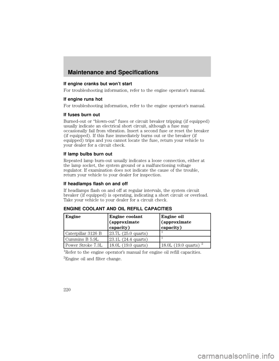
ENGINE COOLANT AND OIL REFILL CAPACITIES
Engine Engine coolant
(approximate
capacity)Engine oil
(approximate
capacity)
Caterpillar 3126 B 23.7L (25.0 quarts)
1
Cummins B 5.9L 23.1L (24.4 quarts)1
Power Stroke 7.3L 18.0L (19.0 quarts) 18.0L (19.0 quarts)2
1
Refer to the engine operator's manual for engine oil refill capacities.
2Engine oil and filter change.
Maintenance and Specifications
220