engine FORD F750 2004 11.G Workshop Manual
[x] Cancel search | Manufacturer: FORD, Model Year: 2004, Model line: F750, Model: FORD F750 2004 11.GPages: 264, PDF Size: 1.47 MB
Page 135 of 264
•After you have traveled 80 km (50 miles), thoroughly check your
hitch, electrical connections and trailer wheel lug nuts.
•To aid in engine/transmission cooling and A/C efficiency during hot
weather while stopped in traffic, place the gearshift lever in P (Park)
(if available on your automatic transmission) or N (Neutral) (manual
transmissions and automatic transmissions without a P [Park]
position).
•Vehicles with trailers should not be parked on a grade. If you must
park on a grade, place wheel chocks under the trailer’s wheels.
2004 F650/750(f67)
Supplement
USA English(fus)
Driving
135
Page 138 of 264
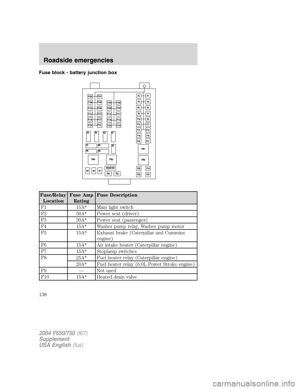
Fuse block - battery junction box
Fuse/Relay
LocationFuse Amp
RatingFuse Description
F1 15A* Main light switch
F2 30A* Power seat (driver)
F3 30A* Power seat (passenger)
F4 15A* Washer pump relay, Washer pump motor
F5 15A* Exhaust brake (Caterpillar and Cummins
engine)
F6 15A* Air intake heater (Caterpillar engine)
F7 15A* Stoplamp switches
F8 25A* Fuel heater relay (Caterpillar engine)
20A* Fuel heater relay (6.0L Power Stroke engine)
F9—Not used
F10 15A* Heated drain valve
2004 F650/750(f67)
Supplement
USA English(fus)
Roadside emergencies
138
Page 139 of 264
Fuse/Relay
LocationFuse Amp
RatingFuse Description
F11—Not used
F12—Not used
F13 10A* Parking brake
F14—Not used
F15 7.5A* Body builder - trailer adapter stoplamps
F16 5A* WABCO hydraulic ABS
F17—Not used
F18 10A* Fuel transfer pump
F19—Not used
F20 10A* Engine ECM power relay (6.0L Power Stroke
engine)
F21 10A* Control for Hydro-max motor
F22 10A* V8 engine IDM2 logic power
F23—Not used
F24—Not used
F101 30A** Air ABS relay, Hydraulic modulator relay
F102 20A** Ignition switch to customer access
F103 50A** Ignition switch, Central Junction Box (CJB)
fuses 8, 9, 10, 11, 19, 20, 23, 24, 25, 29, 30,
31
F104 20A** Power point
F105 20A** Door lock switches
F106 30A** Main light switch, Multifunction switch, CJB
fuses 16, 26 and 28, Headlamps, DRL relays
F107 50A** CJB fuses 1, 2, 3, 4, 12, 13, 14, 15
F108 40A** Fuel heater relay (Cummins engine)
F109 40A** Power window relay
F110—Not used
F111 30A** Park lamps relay, Park lamps
F112 40A** Blower motor relay, Blower motor
F113 30A** Heated seats
F114 25A** Hydraulic ABS ECU power
2004 F650/750(f67)
Supplement
USA English(fus)
Roadside emergencies
139
Page 140 of 264
Fuse/Relay
LocationFuse Amp
RatingFuse Description
F115 40A** Ignition switch, CJB fuse 21
F116 30A** Turn relays and back-up lamp relay
F117 20A** Stoplamp relay (Caterpillar and Cummins
engine)
F118 60A** Trailer tow left, right and ABS fuse block
(Hydraulic brake vehicles)
F119/F120 60A** Trailer tow fuse block, Stop/Tail/Marker
lamps
F121/F122 60A** Trailer tow fuse block (Air brake vehicles),
Left, right and ABS, Hydraulic HydroMax
pump motor fuse relay
R1–201—Washer pump relay
R2–202—Wiper speed relay
R3–203—Wiper run-park relay
R4–204—Crank inhibit relay (6.0L Power Stroke
engine)/Exhaust brake relay (Caterpillar and
Cummins engine)
R5–207—Drain valve heater relay
R6–205—RH stop/turn relay
R7–206—LH stop/turn relay
R8–208—Back-up lamps relay
R9–209—ECM ISO relay (6.0L Power Stroke engine)
or Stoplamp relay (Caterpillar and Cummins
engine)
FIR1–301—Fuel heater, Fuel heater-fuel transfer pump
FIR2–302—Park lamp relay
FIR3–303—Blower motor relay
FIR4–304—Air ABS relay, Hydraulic modulator relay
* Mini fuse **Maxi fuse
2004 F650/750(f67)
Supplement
USA English(fus)
Roadside emergencies
140
Page 142 of 264
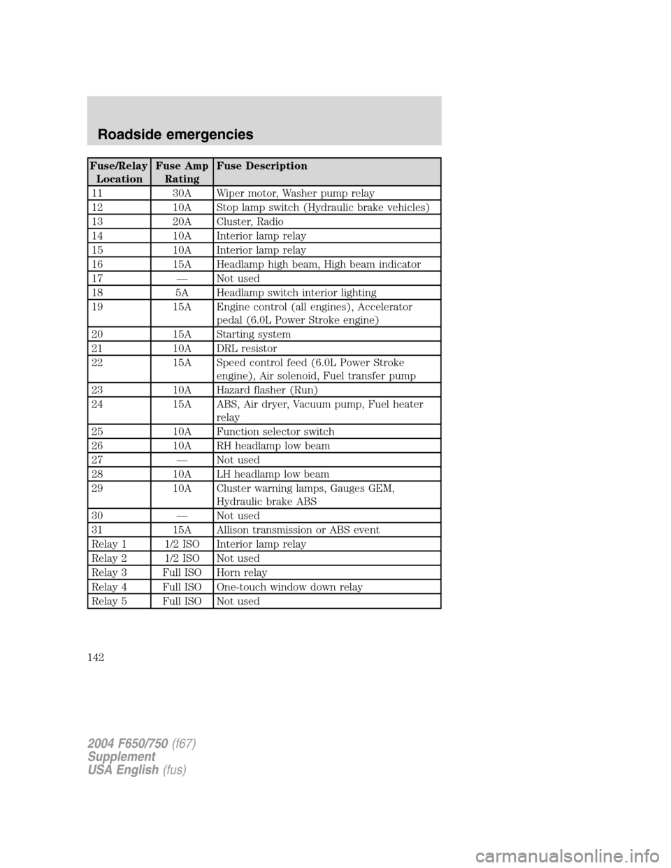
Fuse/Relay
LocationFuse Amp
RatingFuse Description
11 30A Wiper motor, Washer pump relay
12 10A Stop lamp switch (Hydraulic brake vehicles)
13 20A Cluster, Radio
14 10A Interior lamp relay
15 10A Interior lamp relay
16 15A Headlamp high beam, High beam indicator
17—Not used
18 5A Headlamp switch interior lighting
19 15A Engine control (all engines), Accelerator
pedal (6.0L Power Stroke engine)
20 15A Starting system
21 10A DRL resistor
22 15A Speed control feed (6.0L Power Stroke
engine), Air solenoid, Fuel transfer pump
23 10A Hazard flasher (Run)
24 15A ABS, Air dryer, Vacuum pump, Fuel heater
relay
25 10A Function selector switch
26 10A RH headlamp low beam
27—Not used
28 10A LH headlamp low beam
29 10A Cluster warning lamps, Gauges GEM,
Hydraulic brake ABS
30—Not used
31 15A Allison transmission or ABS event
Relay 1 1/2 ISO Interior lamp relay
Relay 2 1/2 ISO Not used
Relay 3 Full ISO Horn relay
Relay 4 Full ISO One-touch window down relay
Relay 5 Full ISO Not used
2004 F650/750(f67)
Supplement
USA English(fus)
Roadside emergencies
142
Page 144 of 264
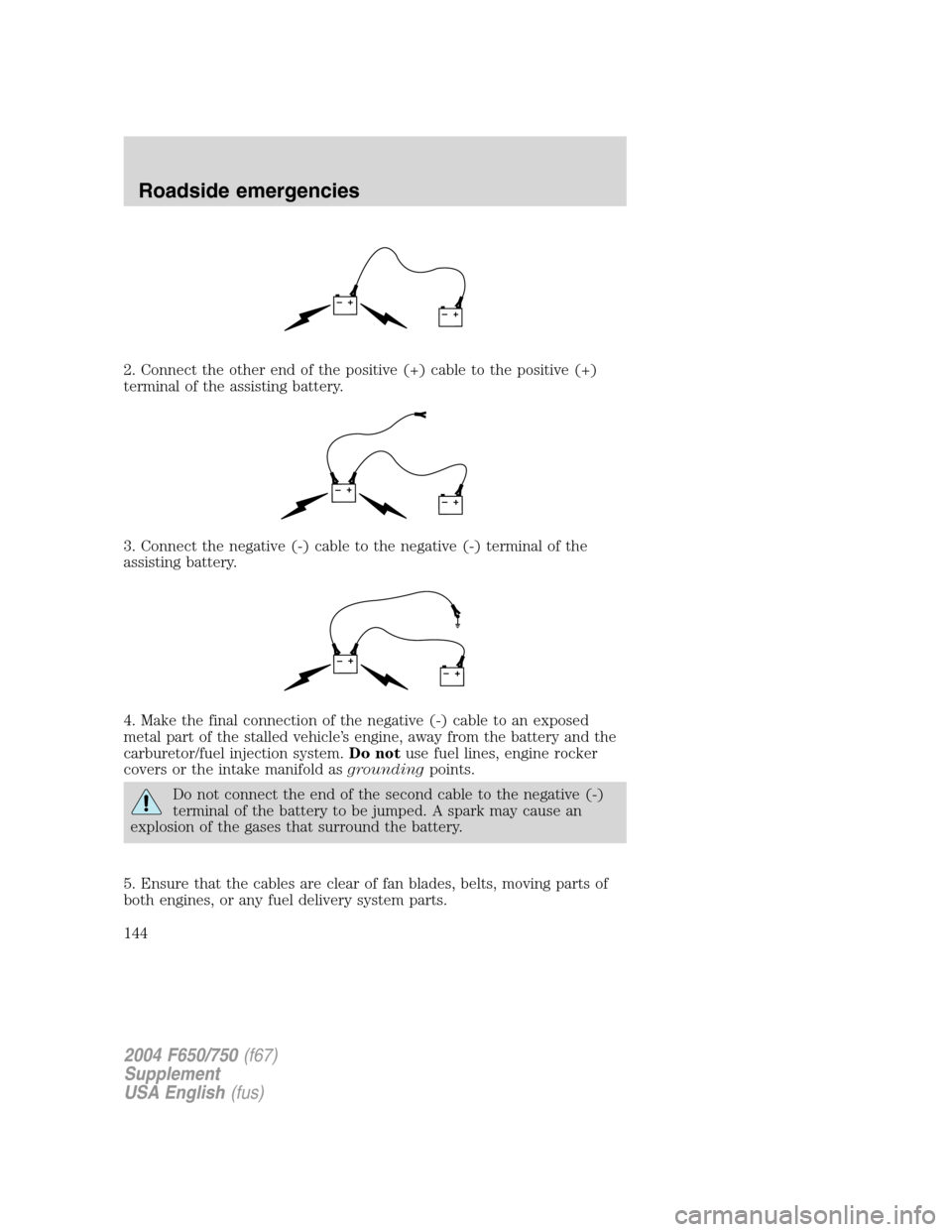
2. Connect the other end of the positive (+) cable to the positive (+)
terminal of the assisting battery.
3. Connect the negative (-) cable to the negative (-) terminal of the
assisting battery.
4. Make the final connection of the negative (-) cable to an exposed
metal part of the stalled vehicle’s engine, away from the battery and the
carburetor/fuel injection system.Do notuse fuel lines, engine rocker
covers or the intake manifold asgroundingpoints.
Do not connect the end of the second cable to the negative (-)
terminal of the battery to be jumped. A spark may cause an
explosion of the gases that surround the battery.
5. Ensure that the cables are clear of fan blades, belts, moving parts of
both engines, or any fuel delivery system parts.
+–+–
+–+–
+–+–
2004 F650/750(f67)
Supplement
USA English(fus)
Roadside emergencies
144
Page 145 of 264
Jump starting
1. Start the engine of the booster vehicle and run the engine at
moderately increased speed.
2. Start the engine of the disabled vehicle.
3. Once the disabled vehicle has been started, run both engines for an
additional three minutes before disconnecting the jumper cables.
Removing the jumper cables
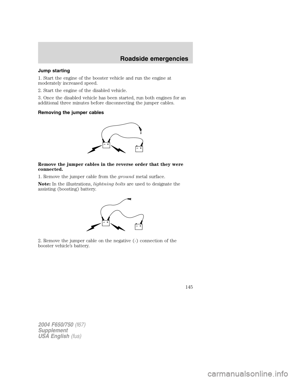
Remove the jumper cables in the reverse order that they were
connected.
1. Remove the jumper cable from thegroundmetal surface.
Note:In the illustrations,lightning boltsare used to designate the
assisting (boosting) battery.
2. Remove the jumper cable on the negative (-) connection of the
booster vehicle’s battery.
+–+–
+–+–
2004 F650/750(f67)
Supplement
USA English(fus)
Roadside emergencies
145
Page 146 of 264
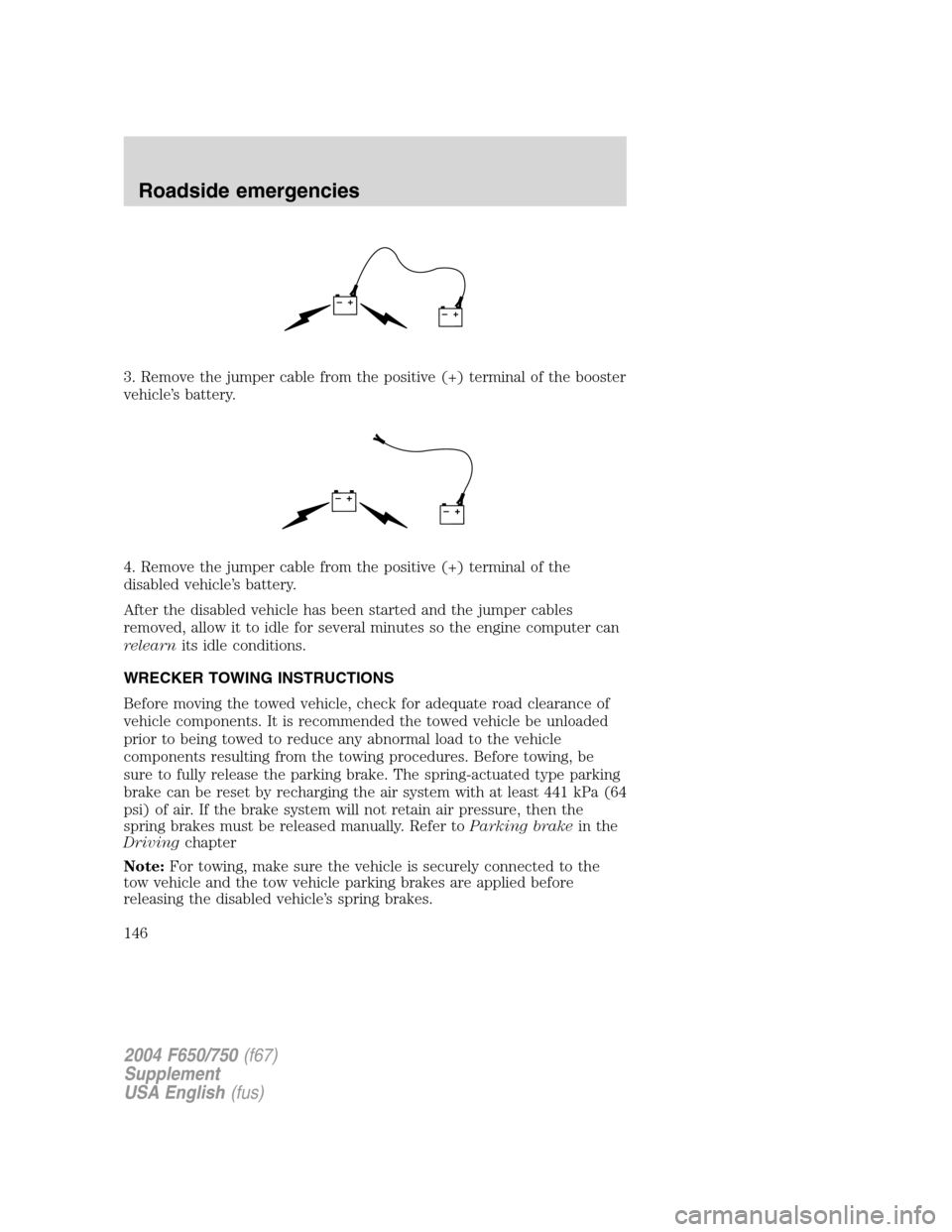
3. Remove the jumper cable from the positive (+) terminal of the booster
vehicle’s battery.
4. Remove the jumper cable from the positive (+) terminal of the
disabled vehicle’s battery.
After the disabled vehicle has been started and the jumper cables
removed, allow it to idle for several minutes so the engine computer can
relearnits idle conditions.
WRECKER TOWING INSTRUCTIONS
Before moving the towed vehicle, check for adequate road clearance of
vehicle components. It is recommended the towed vehicle be unloaded
prior to being towed to reduce any abnormal load to the vehicle
components resulting from the towing procedures. Before towing, be
sure to fully release the parking brake. The spring-actuated type parking
brake can be reset by recharging the air system with at least 441 kPa (64
psi) of air. If the brake system will not retain air pressure, then the
spring brakes must be released manually. Refer toParking brakein the
Drivingchapter
Note:For towing, make sure the vehicle is securely connected to the
tow vehicle and the tow vehicle parking brakes are applied before
releasing the disabled vehicle’s spring brakes.
+–+–
+–+–
2004 F650/750(f67)
Supplement
USA English(fus)
Roadside emergencies
146
Page 151 of 264
In order to help you service your Ford vehicle, please have the following
information available when contacting the Commercial Vehicle Hotline:
•Your telephone number (home and business)
•The name of the dealer and the city where the dealership is located
•The year and make of your vehicle
•The date of vehicle purchase
•The current odometer reading
•The vehicle identification number (VIN)
If you still have a complaint involving a warranty dispute, you must
directly notify Ford in writing before pursuing remedies under your
state’s warranty laws. Ford is also allowed a final repair attempt in some
states.
GETTING ASSISTANCE OUTSIDE THE U.S AND CANADA
Before exporting your vehicle to a foreign country, contact the
appropriate foreign embassy or consulate. These officials can inform you
of local vehicle registration regulations and where to find unleaded fuel.
If you cannot find unleaded fuel or can only get fuel with an anti-knock
index lower than is recommended for your vehicle, contact a district or
owner relations/customer relationship office.
The use of leaded fuel in your vehicle without proper conversion may
damage the effectiveness of your emission control system and may cause
engine knocking or serious engine damage. Ford Motor Company/Ford of
Canada is not responsible for any damage caused by use of improper
fuel.
In the United States, using leaded fuel may also result in difficulty
importing your vehicle back into the U.S.
If your vehicle must be serviced while you are traveling or living in
Central or South America, the Caribbean, or the Middle East, contact the
nearest Ford dealership. If the dealership cannot help you, write or call:
FORD MOTOR COMPANY
WORLDWIDE DIRECT MARKET OPERATIONS
1555 Fairlane Drive
Fairlane Business Park #3
Allen Park, Michigan 48101
U.S.A.
Telephone: (313) 594-4857
FAX: (313) 390-0804
2004 F650/750(f67)
Supplement
USA English(fus)
Customer assistance
151
Page 155 of 264
PAINT CHIPS
Your dealer has touch-up paint and sprays to match your vehicle’s color.
Take your color code (printed on a sticker in the driver’s door jam) to
your dealer to ensure you get the correct color.
•Remove particles such as bird droppings, tree sap, insect deposits, tar
spots, road salt and industrial fallout before repairing paint chips.
•Always read the instructions before using the products.
ALUMINUM WHEELS AND COVERS
Aluminum wheel rims or covers are coated with a clearcoat paint finish.
In order to maintain their shine:
•Clean with Motorcraft Wheel and Tire Cleaner (ZC-37–A), which is
available from your dealer.
•Never apply any cleaning chemical to hot or warm wheel rims or
covers.
•Some automatic car washes may cause damage to the finish on your
wheel rims or covers. Chemical-strength cleaners, or cleaning
chemicals, in combination with brush agitation to remove brake dust
and dirt, could wear away the clearcoat finish over time.
•Do not use hydrofluoric acid-based or high caustic-based wheel
cleaners, steel wool, fuels or strong household detergent.
•To remove tar and grease, use Ford Extra Strength Tar and Road Oil
Removal (B7A-19520–AA), available from your dealer.
ENGINE
Engines are more efficient when they are clean because grease and dirt
buildup keep the engine warmer than normal. When washing:
•Take care when using a power washer to clean the engine. The
high-pressure fluid could penetrate the sealed parts and cause
damage.
•Do not spray a hot engine with cold water to avoid cracking the
engine block or other engine components.
•Spray Motorcraft Engine Shampoo and Degreaser (ZC-20) on all parts
that require cleaning and pressure rinse clean.
•Never wash or rinse the engine while it is running; water in the
running engine may cause internal damage.
2004 F650/750(f67)
Supplement
USA English(fus)
Cleaning
155