transmission FORD F750 2006 11.G Service Manual
[x] Cancel search | Manufacturer: FORD, Model Year: 2006, Model line: F750, Model: FORD F750 2006 11.GPages: 272, PDF Size: 1.86 MB
Page 156 of 272
To reduce the risk of personal injury or property damage when
manually releasing the spring brakes, be sure to block the wheels
so the vehicle cannot move once the brakes are released.
Towing the vehicle with the front wheels suspended
When it is necessary to tow a vehicle with the front wheels suspended,
extra precautions must be taken to avoid transmission or differential
damage. Proceed as follows:
•Remove the axle shafts from the axle assembly to prevent the wheels
from driving the differential and the transmission.
•The wheel hub ends must be covered to prevent loss of axle lubricant
and entrance of other contaminants. If the axle shafts are not
removed, removal of the propeller shaft is required.
Note:To avoid transmission damage, vehicles should not be towed even
a short distance without suspending rear wheels or removing the axle
shaft or propeller shaft.
Note:In the event the chassis is equipped with a tandem axle and the
vehicle is to be towed from the front, the forward rear axle may be
raised to clear the road surface and secured to the frame by chains or
U-bolts, allowing only the rear rear axle to contact the road surface. Axle
shafts must be removed from the rear rear axle assembly. The wheel hub
ends must be covered to prevent loss of axle lubricant and entrance of
contaminants. Use extreme care in securing the chains or U-bolts to
avoid possible damage to the brake lines, hoses or other components.
Towing vehicles equipped with a driver-controlled differential lock
Note:If the vehicle must be towed to a service facility with the drive
axle wheels on the ground, it is necessary to remove the axle shafts
before the vehicle is towed.
2006 F-650/750(f67)
Supplement
USA(fus)
Roadside Emergencies
156
Page 158 of 272
Installing the axle shafts
1. Remove the covers from the wheel ends
2. Shift the differential lock to the unlocked position (disengaged)
position.
3. Install the axle shafts
•Place the gaskets on the wheel hub studs.
•Push the right-hand axle shaft and gasket into the wheel end and
housing until the shaft stops against the differential shift collar.
•Push down and in on the axle shaft flange and rotate the shaft until
the splines of the shaft and shift collar are engaged.
•Push the axle shaft further into the housing until the shaft stops
against the differential side gear.
•Push down on the axle shaft flange and rotate the shaft until the
splines of the shaft and side gear are engaged.
•Push the axle shaft completely into the housing until the axle shaft
flange and the gasket are flush against the wheel hub.
•Install the left-hand axle shaft and gasket into the wheel end.
4. If tapered dowels are required, install them at each stud and into the
flange of the axle shaft. Use a punch or drift and hammer, if needed.
5. Install the fasteners and tighten to correct torque value. Refer to the
Service Manual section.
Towing the vehicle with the rear wheels suspended
Note:To avoid damage to the cab roof or air deflector when towing the
vehicle backward (rear wheels suspended) the air deflector must be
removed.
Whenever possible, it is preferable to tow a disabled vehicle from the
rear by raising the rear of the chassis. When towing a vehicle with the
rear of the chassis suspended the front wheels must be locked in the
straight-ahead position.
Vehicles equipped with a manual-shift transmission must have at least
1.0 pint (0.5L) of transmission fluid drained from the case. This will
prevent the transmission fluid from entering the clutch housing and fluid
saturating the clutch discs. Make sure that the transmission fluid is
replaced before the vehicle is returned to service.
2006 F-650/750(f67)
Supplement
USA(fus)
Roadside Emergencies
158
Page 176 of 272
If you must leave the engine running while checking under the
hood, do not allow any loose clothing, jewelry, hair or other
items to get near moving engine components or possible personal
injury may occur.
To open the hood:
1. Set the parking brake, shift into N (Neutral) (automatic transmission)
or 1 (First) (manual transmission) and turn the engine off.
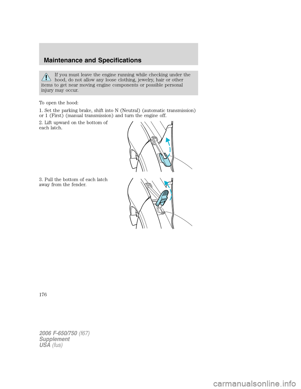
2. Lift upward on the bottom of
each latch.
3. Pull the bottom of each latch
away from the fender.
2006 F-650/750(f67)
Supplement
USA(fus)
Maintenance and Specifications
176
Page 177 of 272
4. Tilt the hood forward until
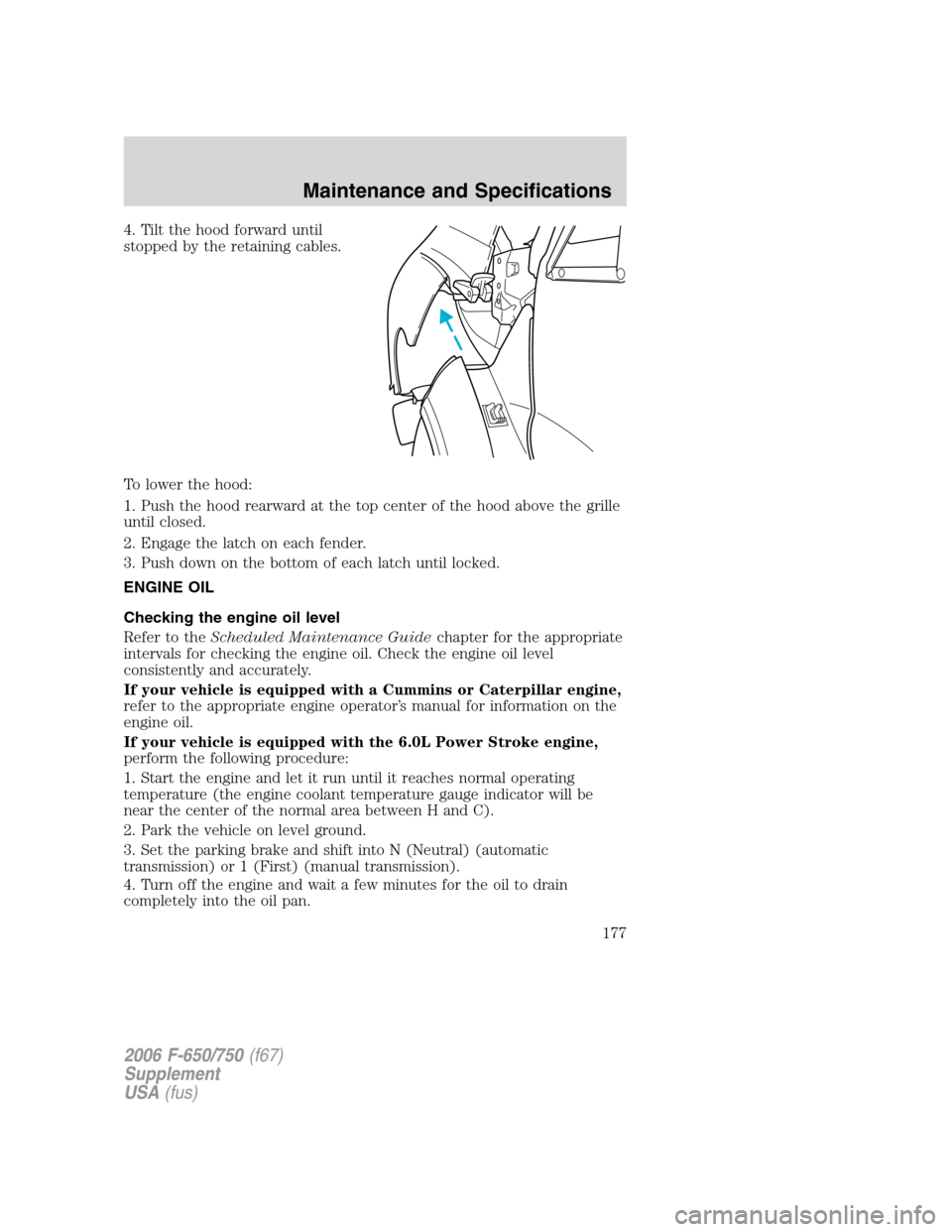
stopped by the retaining cables.
To lower the hood:
1. Push the hood rearward at the top center of the hood above the grille
until closed.
2. Engage the latch on each fender.
3. Push down on the bottom of each latch until locked.
ENGINE OIL
Checking the engine oil level
Refer to theScheduled Maintenance Guidechapter for the appropriate
intervals for checking the engine oil. Check the engine oil level
consistently and accurately.
If your vehicle is equipped with a Cummins or Caterpillar engine,
refer to the appropriate engine operator’s manual for information on the
engine oil.
If your vehicle is equipped with the 6.0L Power Stroke engine,
perform the following procedure:
1. Start the engine and let it run until it reaches normal operating
temperature (the engine coolant temperature gauge indicator will be
near the center of the normal area between H and C).
2. Park the vehicle on level ground.
3. Set the parking brake and shift into N (Neutral) (automatic
transmission) or 1 (First) (manual transmission).
4. Turn off the engine and wait a few minutes for the oil to drain
completely into the oil pan.
2006 F-650/750(f67)
Supplement
USA(fus)
Maintenance and Specifications
177
Page 189 of 272
•Check tie rod, drag link end clamp bolts and ball joints. They must be
tight.
•Check for installation and spread of cotter pins and tightness of nuts
at both ends of the tie rod and drag link.
•Check that pitman arm (steering arm at steering gear) mounting is
tight and locked. Check system for leaks or hose chafing. Repair at
once.
•Maintain proper steering gear and power steering pump lubricant
levels.
•Regularly inspect steering column joint bolts and steering linkage,
particularly for body-to-chassis clearance.
Note:Have any steering problems corrected at once by a qualified
service technician.
Failure to maintain the steering system in proper condition can
cause reduced steering ability resulting in property damage,
personal injury or death.
Tightening steering column joint bolts
As a good maintenance practice, it is recommended that steering column
joint bolts be checked for tightness every 60,000 miles (96,000 km) or
annually, whichever occurs first. DO NOT OVERTIGHTEN.
Power steering
Whenever the power steering’s hydraulic system has been drained and
refilled for any reason, air must be bled from the system before returning
the vehicle to service. Failure to properly bleed the hydraulic system can
result in degradation of power system performance.
Consult your dealer who is aware of the proper procedures for filling and
bleeding the system.
Power steering fluid
Check the power steering fluid level using the following procedure. If
adding fluid is necessary, refer toLubricant Specificationsin this
chapter for the proper fluid type. Refer to theScheduled Maintenance
Guidechapter for the recommended service intervals.
1. Set the parking brake, shift into N (Neutral) (automatic transmission)
or 1 (First) (manual transmission) and turn the engine off.
2006 F-650/750(f67)
Supplement
USA(fus)
Maintenance and Specifications
189
Page 191 of 272
During normal operation, the fluid level in the clutch reservoir should
remain constant. If the fluid level drops, maintain the fluid level at the
step in the reservoir.
Use only a DOT 3 brake fluid designed to meet manufacturer
specifications. Refer toLubricant specificationsin this chapter.
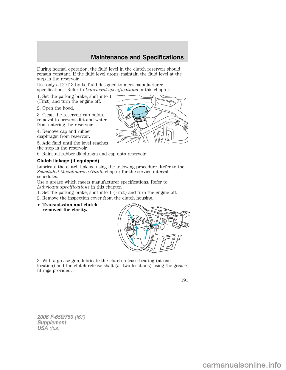
1. Set the parking brake, shift into 1
(First) and turn the engine off.
2. Open the hood.
3. Clean the reservoir cap before
removal to prevent dirt and water
from entering the reservoir.
4. Remove cap and rubber
diaphragm from reservoir.
5. Add fluid until the level reaches
the step in the reservoir.
6. Reinstall rubber diaphragm and cap onto reservoir.
Clutch linkage (if equipped)
Lubricate the clutch linkage using the following procedure. Refer to the
Scheduled Maintenance Guidechapter for the service interval
schedules.
Use a grease which meets manufacturer specifications. Refer to
Lubricant specificationsin this chapter.
1. Set the parking brake, shift into 1 (First) and turn the engine off.
2. Remove the inspection cover from the clutch housing.
•Transmission and clutch
removed for clarity.
3. With a grease gun, lubricate the clutch release bearing (at one
location) and the clutch release shaft (at two locations) using the grease
fittings provided.
2006 F-650/750(f67)
Supplement
USA(fus)
Maintenance and Specifications
191
Page 192 of 272
4. Lubricate clutch release wear pads at the two locations where they
contact the clutch release bearing using a brush or similar tool.
5. Install the inspection cover onto the clutch housing.
TRANSMISSION FLUID
Always dispose of used automotive fluids in a responsible manner.
Follow your community’s standards for disposing of these types of fluids.
Call your recycling center to find out about recycling automotive fluids.
Automatic transmission fluid
Refer to your Allison Automatic Transmission Operator’s Manual for
scheduled intervals for transmission fluid checks and changes. Your
transmission does not consume fluid. However, the fluid level should be
checked if the transmission is not working properly, i.e., if the
transmission slips or shifts slowly or if you notice some sign of fluid
leakage.
Automatic transmission fluid expands when warmed. To obtain an
accurate fluid check, drive the vehicle until it is warmed up
(approximately 20 miles [30 km]). If your vehicle has been operated for
an extended period at high speeds, in city traffic or during hot weather,
the vehicle should be turned off for about 30 minutes to allow fluid to
cool before checking.
1. Drive the vehicle 20 miles (30 km) or until it reaches normal operating
temperature.
2. Park the vehicle on a level surface and engage the parking brake.
3. With the parking brake engaged and your foot on the brake pedal,
start the engine and move the gearshift lever through all of the gear
ranges. Allow sufficient time for each gear to engage.
4. Place the gearshift lever in N (Neutral) or P (Park) and leave the
engine running.
5. Remove the dipstick, wiping it clean with a clean, dry lint free rag.
6. Install the dipstick making sure it is fully seated in the filler tube.
7. Remove the dipstick and inspect the fluid level.
If you must add transmission fluid, make sure the correct type of fluid is
being used. The type of fluid used is indicated in your Allison Automatic
Transmission Operator’s Manual.
Fluid levels above the safe range may result in transmission failure; an
overfill condition of transmission fluid may cause shift and/or
engagement concerns and/or possible damage.
2006 F-650/750(f67)
Supplement
USA(fus)
Maintenance and Specifications
192
Page 193 of 272
Use of a non-approved automatic transmission fluid may cause
internal transmission component damage.
Manual transmission fluid
Refer to theScheduled Maintenance Guidechapter for transmission
fluid level checks and fluid change intervals.
Your manual transmission may be filled with an optional synthetic fluid
which allows the use of extended service intervals. A tag on the filler
plug will identify the use of the synthetic fluid.
Use only fluid that meets manufacturer specifications (refer to
Lubricant specificationsin this chapter.
Use of a non-approved transmission fluid may cause internal
transmission component damage.
Check your transmission fluid level using the following procedure:
1. Park the vehicle on level ground.
2. Set the parking brake and shift into 1 (First) and turn the engine off.
3. Clean any dirt from around the filler plug.
4. Remove the filler plug and inspect the fluid level.
5. The fluid level should be up to the bottom of the filler plug opening.
6. If necessary, add enough fluid through the filler plug opening so that
the fluid level is at the bottom of the opening.
7. Clean and install the filler plug securely.
Drain and refill your transmission fluid using the following procedure:
1. Drain the transmission while the fluid is warm.
2. Park the vehicle on level ground.
3. Set the parking brake and shift into 1 (First) and turn the engine off.
4. Clean any dirt from around the filler and drain plugs.
5. Remove the filler and drain plugs and drain the fluid into a suitable
container. Dispose all used automotive fluids in a responsible manner
following your local authorized standards.
6. Clean and install the drain plug securely.
7. Add enough fluid through the filler plug opening so that the fluid level
is up to the bottom of the opening.
8. Clean and install the filler plug securely.
2006 F-650/750(f67)
Supplement
USA(fus)
Maintenance and Specifications
193
Page 202 of 272
•Multiply liters used by 100, then divide by total kilometers traveled.
Keep a record for at least one month and record the type of driving (city
or highway). This will provide an accurate estimate of the vehicle’s fuel
economy under current driving conditions. Additionally, keeping records
during summer and winter will show how temperature impacts fuel
economy. In general, lower temperatures give lower fuel economy.
Driving style - good driving and fuel economy habits
Give consideration to the lists that follow and you may be able to change
a number of variables and improve your fuel economy.
Habits
•Smooth, moderate operation can yield up to 10% savings in fuel.
•Steady speeds without stopping will usually give the best fuel
economy.
•Anticipate stopping; slowing down may eliminate the need to stop.
•Sudden or hard accelerations may reduce fuel economy.
•Slow down gradually.
•Driving at reasonable speeds (traveling at 55 mph [88 km/h] uses 15%
less fuel than traveling at 65 mph [105 km/h]).
•Using the air conditioner or defroster may reduce fuel economy.
•Resting your foot on the brake pedal while driving may reduce fuel
economy.
Conditions
•Carrying unnecessary weight may reduce fuel economy.
•Fuel economy may decrease with lower temperatures during the first
8–10 miles (12–16 km) of driving.
•Flat terrain driving improves fuel economy over hilly roads.
•Transmissions give their best fuel economy when operated in the top
cruise gear and with steady pressure on the accelerator.
•Close windows for highway driving.
NOISE EMISSIONS – EXTERIOR
In order to comply with the federal exterior noise regulations, your
vehicle may be equipped with noise emission items. Depending on the
vehicle configuration, it may have all or some of the following items:
2006 F-650/750(f67)
Supplement
USA(fus)
Maintenance and Specifications
202
Page 203 of 272
Air Intake System
•Air Cleaner:should be inspected and its location should not be
altered. Do not alter inlet and outlet piping.
Body
•Wheel Well:splash shields, cab shields and under-hood insulation
should be inspected for deterioration, dislocation, and orientation.
Cooling System
•Check the fan for damage to blades; replace, if damaged, with the
recommended parts. Inspect for fan to shroud interference, and any
damage to shroud such as cracks and holes.
•The fan ratio should not be changed and the fan spacer dimensions
and positions should not be altered.
•Inspect the fan clutch for proper operation, make sure that the fan is
disengaged when cooling of the engine is not required.
•Check for proper operation of radiator shutters, if equipped. The
shutters should be open during normal operating temperatures.
Engine and Driveline System
•Transmission Enclosure:inspect for cracks, holes, and tears. Clean
any deposits such as oil, dirt, and stones.
•Engine valve covers and block covers are made to damp out engine
mechanical noise and, if needed, should be replaced with
recommended parts. Check for mechanical isolations.
Exhaust System
•Inspect the exhaust system for leaks at various joint connections and
tighten the clamps.
•Do a visual inspection for cracks or holes in the muffler and tail pipe.
•Always use the recommended parts when items need to be replaced.
•The tail pipe elbow or offset tail pipe orientation must not be changed
from the standard position as originally received.
•To avoid abnormal changes in vehicle sound levels, it is necessary for
the owner to perform inspections and necessary maintenance at the
intervals shown in theScheduled Maintenance Guidechapter.
CHASSIS-MOUNTED CHARGE AIR COOLER
Inspect charge air cooler daily
With the engine off, visually inspect the charge air cooler core assembly
for debris and clogging of external fins. Prior to engine operation,
remove any debris blocking the core.
2006 F-650/750(f67)
Supplement
USA(fus)
Maintenance and Specifications
203