catalytic converter FORD FESTIVA 1991 Service Manual
[x] Cancel search | Manufacturer: FORD, Model Year: 1991, Model line: FESTIVA, Model: FORD FESTIVA 1991Pages: 454, PDF Size: 9.53 MB
Page 51 of 454
CATALYTIC CONVERTER
Continued operation of vehicle with a severe malfunction could cause converter to overheat, resulting in possible damage to converter and
ve h ic l e .
Any modification to the exhaust system on turbo models, which reduces exhaust backpressure, will lead to lean fuel mixtures and excessive
spark advance. This could cause serious engine damage.
ELECTROSTATIC DISCHARGE SENSITIVE (ESD) PARTS
ENGINE OIL
FUEL PUMP SHUTOFF SWITCH
This switch stops flow of fuel to engine after a collision. The impact does not have to be great for switch to be triggered. Switch must be reset
after collision. Switch is located under left rear speaker in luggage compartment. Press button to reset switch.
FUEL SYSTEM SERVICE
HALOGEN BULBS
PASSIVE RESTRAINTS
RADIATOR CAP
RADIATOR FAN WARNING:Many solid state electrical com ponents can be dam aged by static electricity (ESD). Som e will display a
warning label, but m any will not. Discharge personal static electricity by touching a m etal ground point
on the vehicle prior to servicing any ESD sensitive com ponent.
CAUT ION: Never use non-detergent or straight m ineral oil.
WARNING:Relieve fuel system pressure prior to servicing any fuel system com ponent (fuel injection m odels).
WARNING:Halogen bulbs contain pressurized gas which m ay explode if overheated. DO NOT touch glass portion
of bulb with bare hands. Eye protection should be worn when handling or working around halogen
bulbs.
CAUT ION: Before operating vehicle, securely fasten passive shoulder restraints to the em ergency release buckles.
T he buckle fits in only one way. Ensure to position it properly.
CAUT ION: Always disconnect the fan m otor when working near the radiator fan. T he fan is tem perature controlled
and could start at any tim e even when the ignition key is in the OFF position. DO NOT loosen or rem ove
radiator cap when cooling system is hot.
WARNING:Keep hands away from radiator fan. Fan is controlled by a therm ostatic switch which m ay com e on or
run for up to 15 m inutes even after engine is turned off.
Copyr ight 2009 Mitchell Repair Information Company, LLC. All Rights Reserved.
Article GUID: A00058075
Page 3 of 3 MITCHELL 1 ARTICLE - FUSES & CIRCUIT BREAKERS Fuses & Circuit Breakers 1988-93 Festiva
3/10/2009 http://www.eautorepair.net/app/PrintItems.asp?S0=2097152&S1=0&SG=%7B7DD6473C%2DB5BB%2D4F20%2D9D70%2D
...
Page 101 of 454
Back To Article
ENGINE OVERHAUL
1991-92 FORD MOT OR CO. ENGINES 1.3L & 1.6L 4-Cylinder
ENGINE IDENTIFICATION
Engine can be identified by Vehicle Identification Number (VIN) on metal tab attached to instrument panel. Tab is close to windshield on
driver's side and is visible through windshield. VIN has 17 characters. The 8th character identifies engine.
ENGINE IDENTIFICATION CODES
ADJUSTMENTS
VALVE ARRANGEMENT
Firewall Side
In t ake val ves.
Radiator Side
Exhaust valves.
VALVE CLEARANCE ADJUSTMENT
Hydraulic lifters are used. Adjustment is NOT possible nor necessary.
REMOVAL & INSTALLATION
FUEL PRESSURE RELEASE
Remove rear seat. Remove fuel pump access panel. Disconnect fuel pump electrical connector. Start engine and allow to idle until engine dies.
ENGINE
Removal (1.3L)
1. Remove battery and battery tray. Index hood-to-hinge and remove hood. Drain coolant. Drain engine oil and transaxle fluid. Disconnect
vane airflow meter connector, vane airflow meter and hose.
2. Remove oil dipstick, cooling fan and radiator assembly. Disconnect accelerator cable from mounting bracket and throttle lever.
Disconnect speedometer cable at transaxle. Mark and disconnect fuel lines at fuel pump. Plug fuel lines. Remove heater hoses. Remove
brake booster vacuum hose. Disconnect transaxle vacuum hose.
3. Remove charcoal canister hoses from engine. Disconnect engine wiring harness. Remove alternator and brackets. Remove engine ground
strap. Raise vehicle and remove catalytic converter.
4. Disconnect A/C compressor without removing hoses, and set compressor aside. Disconnect distributor wiring at coil. On automatic
transaxle models, remove shift lever-to-manual shaft assembly nut. Remove shift cable from transaxle. Loosen front wheel bolts. Raise
vehicle and remove wheel assemblies.
5. Remove stabilizer mounting nuts and brackets. Remove lower arm clamp bolts and nuts. Pull lower arms downward, separating lower
arms from knuckles. Separate halfshafts and install Differential Plugs (T87C-7025-C) between differential side gears. See FWD AXLE
SHAFTS article in DRIVE AXLES Section.
6. On manual transaxle vehicles, disconnect clutch control cable and shift control cable rod. Remove stabilizer bar from transaxle. Remove
catalytic converter inlet pipe. Support engine assembly with hoist. Remove rear crossmember mount bolts. Remove front and rear engine
mount nuts.
7. Remove crossmember. Lower vehicle and attach engine lift hooks. Remove right engine mount bolt. Remove engine/transaxle assembly.
Remove gusset plates. Remove starter and flywheel cover. Remove torque converter bolts on automatic transaxle. Remove engine-to-
transaxle bolts. Separate transaxle from engine.
Installation (1.3L)
1. Install transaxle to engine in reverse order of removal. Attach hoist to engine/transaxle assembly and position in vehicle. Support engine
in chassis and install engine mount bolts. Raise vehicle and install front engine mount nut. Tighten nuts to specification. See TORQUE
SPECIFICATIONS table at end of article.
2. Position crossmember onto mounts and chassis. Tighten rear nut. Install mount-to-crossmember nuts and tighten. Remove differential
plugs and install halfshafts. To complete installation, reverse removal procedure. Tighten all bolts/nuts to specifications. Fill all fluid NOTE:For engine repair procedures not covered in this article, see ENGINE OVERHAUL PROCEDURES
-
GENERAL INFORMATION
article in the GENERAL INFORMAT ION section.
ApplicationVIN Code
Festiva
1.3L SOHC PFIH
Capri
1.6L DOHC PFIZ
1.6L DOHC PFI TURBO6
NOTE:When rem oving engine m ounts, m ark and note location and position to ensure proper installation.
Engine and transaxle are rem oved as an assem bly.
Page 1 of 19 MITCHELL 1 ARTICLE - ENGINE OVERHAUL 1991-92 FORD MOTOR CO. ENGINES 1.3L & 1.6L 4-Cylinder
3/10/2009 http://www.eautorepair.net/app/PrintItems.asp?S0=2097152&S1=0&SG=%7B959286D2%2D3A85%2D4BFC%2D9C5C%2D
...
Page 102 of 454
levels to proper level.
Removal (1.6L & 1.6L Turbo)
1. Relieve fuel pressure and discharge air conditioning system (if equipped). See FUEL PRESSURE RELEASE under REMOVAL &
INSTALLATION. Disconnect and remove battery, battery tray and battery tray support bracket.
2. Release wiring harness retaining straps from battery support tray. Disconnect windshield washer supply hose between fluid reservoir and
hood. Mark hinge locations and remove hood.
3. Disconnect intake air tube and wiring to ignition coil and vane airflow meter. Remove air cleaner/vane airflow meter assembly. Remove
air cleaner assembly support brackets. Disconnect intercooler hoses from turbocharger (if equipped).
4. Drain engine coolant and remove radiator. Disconnect accelerator cable, and remove retaining bracket from cam cover. Position cable to
one side.
5. Disconnect and plug fuel lines at fuel filter and pressure regulator. Disconnect power brake booster manifold vacuum hose from
manifold. Disconnect heater hoses at heater core tubes. Label and remove vacuum hoses located at throttle body.
6. For manual transaxle turbocharged vehicles, disconnect clutch cable and remove support bracket and cable from transmission. On non-
turbo vehicles, disconnect clutch slave hydraulic line. For automatic transaxle, remove transaxle cooler lines.
7. Disconnect starter wiring at starter. Remove harness from locating strap on bracket. Disconnect alternator wiring. Disconnect wiring
from engine coolant sensors located on rear of engine block. Remove ground connection at bracket on thermostat cover. Disconnect O2
sensor wire, main wiring harness connector, TPS connector (turbocharged only), knock sensor connector, distributor wiring and
transaxle wiring. Disconnect ground wire and strap at front of engine, and reinstall lifting eye.
8. Remove engine oil dipstick and retaining clip. Remove power steering pump from mounting bracket. Remove power steering pump
mounting bracket. With hoses attached, position pump aside. Remove upper air conditioning compressor retaining bolts (if equipped).
9. Raise vehicle on hoist. Drain engine oil and cooling system. On vehicles with air conditioning, remove lower air conditioning
compressor mounting bolts, and position compressor out of way.
10. Remove front wheels and tires. Remove front ball joints-to-ste e r in g kn u c kl e s r e t a in in g b o l t s. R e mo ve sp l a sh gu a r d s. Dr a in t ransmission
oil and remove half shafts from differential. Remove front exhaust pipe bracket located on lower side of engine. Disconnect front
exhaust pipe from exhaust manifold, or turbocharger (if equipped).
11. Remove frame support bar-to-engine support bolt. Loosen right control arm bolt and, pivot support bar downward. Disengage rubber
exhaust hangers located directly behind catalytic converter. Allow exhaust system to hang down 6 inches, and support system with
mechanic's wire. Unbolt shift linkage and stabilizer bar at transaxle. Remove nuts from front and rear engine mounts, and lower vehicle.
12. Attach chains onto lift eyes at ends of cylinder head, and support engine with hoist. Remove RH engine mount through bolt. Raise
engine off mounts and slightly pivot engine/transaxle assembly. Disconnect oil pressure sensor and route starter/alternator wiring
harness from engine. Carefully lift engine/transaxle assembly, turn assembly while raising to clear brake master cylinder, shift linkage
universal joint, radiator support and air conditioning lines (if equipped).
13. Remove intake manifold support bracket. Remove gusset plate(s) (if equipped). Remove starter. Remove transaxle-to-engine retaining
bolts. Identify bolts to ensure correct installation. Separate transaxle from engine. On manual transaxle, remove pressure plate, clutch
disc and flywheel. On automatic transaxle, remove flexplate.
Installation (1.6L & 1.6L Turbo)
1. Install transaxle to engine in reverse order of removal. Attach hoist to engine/transaxle assembly and position assembly in vehicle.
Before engine contacts mounts, route starter, alternator and oil pressure sensor wiring, and connect oil pressure sensor. Lower engine
until front mount seats on crossmember. Install through bolt on RH engine mount. DO NOT tighten bolt.
2. Remove hoist. Raise vehicle and support with jackstands. Align rear engine mount to crossmember, and install retaining nuts to front
and rear engine mounts. Tighten nuts to specification. See TORQUE SPECIFICATIONS
table at end of article.
3. On manual transaxles, connect shift coupling and stabilizer. Tighten to specification. On automatic transaxles, connect shift linkage and
oil cooler lines. Tighten linkage retaining bolt, shift cable pivot and oil cooler hose clamps to specification. Connect front exhaust pipe
to manifold (or turbocharger). Install exhaust pipe to support bracket. Tighten bolts to specification. Tighten manifold (or turbocharger)
to specification. Attach rubber exhaust hangers. Position cross brace. Tighten retaining nut and bolt and right control arm front bolt.
4. Install drive axles. Install ball joint retaining bolts and tighten to specification. Mount A/C Compressor to engine (if equipped). Tighten
lower retaining bolts to specification. Install splash guards. Install tire and wheel assemblies. Tighten retaining nuts to specification.
5. Lower vehicle. Install upper A/C compressor retaining bolts (if equipped). Tighten bolts to specification. Tighten RH engine mo u n t
through bolt to specification. Connect alternator wiring.
6. Position power steering pump bracket on stud. Lower pump into engine compartment. Install power steering pump bracket retaining
bolts and nut. Tighten to specification. Install power steering pump and belt. Tighten adjustment nut and pivot bolt to specification.
7. Install engine oil dipstick and retaining clip. Install ground strap and ground wire to cylinder head. Install clutch cable (if equipped).
Connect clutch hydraulic line if equipped with manual transaxle or naturally aspirated. Connect transmission electrical connectors.
Connect fuel lines to fuel filter and pressure regulator. Install intake air tube to throttle body.
8. Install intercooler hoses on turbocharged models. Install air cleaner assembly brackets. Install air cleaner assembly with airflow meter
attached. Install intake air tube. Install coil and airflow meter connectors. Connect coolant crankcase and air bypass hoses. Install
vacuum hoses as noted in disassembly.
9. Connect accelerator cable. Install retaining bracket. Install power brake booster hose. Remove speedometer cable from transaxle. Fill
transaxle to specification. See CAPACITIES in SERVICE & ADJUSTMENT SPECIFICATIONS article. Install speedometer cable.
Connect speedometer cable connector. Fill engine oil to capacity.
10. Install radiator/fan assembly. Tighten bracket retaining bolts to specification. Connect coolant hoses and fan electrical connector. Fill
coolant to specification.
11. Install hood and connect washer hose. Install battery tray support, battery tray, battery and battery hold-down. Connect battery
terminal. Evacuate and charge air conditioning system (if equipped). Road test vehicle and inspect for leaks.
INTAKE MANIFOLD
Removal (1.3L)
CAUT ION: DO NOT allow com pressor to hang by hoses. T ie up com pressor with m echanic's wire.
Page 2 of 19 MITCHELL 1 ARTICLE - ENGINE OVERHAUL 1991-92 FORD MOTOR CO. ENGINES 1.3L & 1.6L 4-Cylinder
3/10/2009 http://www.eautorepair.net/app/PrintItems.asp?S0=2097152&S1=0&SG=%7B959286D2%2D3A85%2D4BFC%2D9C5C%2D
...
Page 103 of 454
Disconnect negative battery cable. Drain cooling system. Remove air cleaner. Remove intake manifold bracket. Disconnect throttle cable.
Mark and disconnect vacuum hoses, fuel hoses and wiring. Remove intake manifold bolts. Remove intake manifold and gasket.
Installation (1.3L)
Clean all gasket mating surfaces. Ensure surface is free of burrs, scratches and cracks. Replace all gaskets. Position gasket and manifold to
cylinder head. Install bolts and tighten to specification. To complete installation, reverse removal procedure.
Removal (1.6L)
1. Disconnect negative battery terminal. Relieve fuel pressure. See FUEL PRESSURE RELEASE under REMOVAL &
INSTALLATION. Drain cooling system. Disconnect intercooler tube and/or air intake tube. Disconnect air by-pass hoses. Disconnect
main engine harness electrical connection and TPS connector. Disconnect vacuum hoses from throttle body.
2. Disconnect fuel lines from fuel filter and pressure regulator. Disconnect throttle cable. Disconnect hoses from By-pass Air Control valve
( B AC ) . R e mo ve B AC va l ve r e t a in in g n u t a n d b o l t . R e mo ve in t a ke manifold retaining nuts and bolts from support bracket and cylinder
head. Remove intake manifold and throttle body assembly.
Installation (1.6L)
1. Install new intake manifold gasket, ensuring coolant passage openings align with openings in cylinder head and manifold. Install intake
manifold. Tighten retaining nut and bolts and support bracket bolts to specification. See TORQUE SPECIFICATIONS
table at end of
article.
2. Install BAC valve and connect air hoses. Connect throttle cable. Connect fuel lines to fuel filters and pressure regulator. Connect main
engine harness connector and TPS connector. Connect vacuum lines to throttle body. Install intake air tube. Connect intercooler tube
and/or intake air tube. Connect air by-pass hoses. Fill cooling system. Connect negative battery terminal. Start engine and check for
fluid leaks and correct operation.
EXHAUST MANIFOLD
Removal (1.3L)
1. Raise vehicle. Remove catalytic converter inlet pipe at exhaust manifold. Remove pulse air tube nuts at inlet pipe. Remove inlet pipe
support bracket bolts. Lower vehicle. Remove air intake duct. Remove exhaust manifold heat shroud bolts and remove shroud.
2. Disconnect oxygen sensor connector. Remove exhaust manifold nuts and remove exhaust manifold. Remove gasket from inlet pipe and
cylinder head.
Installation
Position new gasket on cylinder head and inlet pipe. Install exhaust manifold and nuts. Tighten nuts to specification. See, at end of article,
TORQUE SPECIFICATIONS
table. To complete installation, reverse removal procedure. Tighten all bolts and nuts to specification.
Removal (1.6L Non-Turbo)
Remove intake air tube. Remove front exhaust pipe to exhaust manifold retaining nuts. Remove exhaust support bracket (if equipped). Remove
heat shield. Disconnect O2 sensor electrical connector. Remove exhaust manifold.
Installation (1.6L Non-Turbo)
Install exhaust manifold gaskets. Install heavier gasket first. Install exhaust manifold and tighten retaining nuts to specification. See TORQUE
SPECIFICATIONS table at end of article. Connect O2 sensor electrical connector. Install manifold heat shield. Install intake air tube.
Connect front exhaust pipe to intake manifold and tighten retaining nuts to specification. Install exhaust support bracket, if removed, and
tighten engine mount bolt to specification. Start engine and check for leaks.
Removal (1.6L Turbo)
1. Disconnect negative battery cable. Drain cooling system. Remove throttle body air intake tube. Disconnect intercooler hose from
turbocharger assembly and position both intercooler hoses out of the way. Remove O2 sensor connector from its retaining clip, and
disconnect O2 sensor. Remove lower heat shield and then upper heat shield. Remove turbocharger side heat shield.
2. Remove power steering pump (leave hoses attached) and lay aside. Disconnect lower radiator hose from water pump. Position power
steering pump to access mounting bracket retaining bolts and nut. Remove both bolts and one nut, and remove bracket from engine.
Remove 2 screws retaining air cleaner duct tube, loosen clamp at turbocharger and position duct tube out of the way. Disconnect
coolant return hose at turbocharger. Remove bolt and brass sealing washers from oil supply line at engine block.
3. Raise vehicle. Remove retaining nuts and washers from exhaust pipe flange. Remove 2 bolts retaining exhaust hangers to engine block.
Slide off two rubber exhaust hangers at catalytic converter. Pull exhaust pipe downward and to LH side of vehicle. Disconnect oil return
hose at turbocharger. Disconnect coolant return hose at turbocharger. Remove 2 retaining bolts from turbocharger support bracket.
Remove 2 bolts retaining coolant by-pass tube outlet to water pump. Lower vehicle.
4. Loosen retaining clamp bolt on coolant by-pass tube at rear of cylinder head. Remove 11 retaining nuts from exhaust manifold. Pull
coolant by-pass tube bracket from exhaust stud, and position tube out of way. Grasp manifold, pull off studs and move assembly slightly
to RH side of engine compartment to clear cooling fan, and remove assembly from vehicle.
5. Working on bench, remove 4 nuts retaining turbocharger to exhaust manifold, separate assembly and discard gasket.
Installation (1.6L Turbo)
NOTE:Feed O2 sensor wire and guide through upper heat shield.
NOTE:When reinstalling turbocharger, thoroughly rem ove all gaskets and sealant. Use new gaskets. Add .85
oz. (25 cc) of engine oil in the oil passage of the turbocharger.
Page 3 of 19 MITCHELL 1 ARTICLE - ENGINE OVERHAUL 1991-92 FORD MOTOR CO. ENGINES 1.3L & 1.6L 4-Cylinder
3/10/2009 http://www.eautorepair.net/app/PrintItems.asp?S0=2097152&S1=0&SG=%7B959286D2%2D3A85%2D4BFC%2D9C5C%2D
...
Page 104 of 454
1. Position new gasket on exhaust manifold, and install turbocharger onto studs. Install 4 retaining nuts and tighten to specification. See
TORQUE SPECIFICATIONS
table at end of article.
2. Remove oil supply line from turbocharger. Position new (2-piece) exhaust gasket on cylinder head with heavy gasket installed first .
Carefully position turbocharger assembly in engine compartment and slide exhaust manifold on studs. Position heater tube bracket onto
exhaust stud. Install 11 retaining nuts onto exhaust manifold and tighten to specification. See TORQUE SPECIFICATIONS
table at
end of article. Tighten heater tube clamp bolt securely.
3. Raise vehicle. Position new gasket and install 2 retaining bolts on heater tube outlet. Install 2 retaining bolts into turbocharger support
bracket and tighten bolts to specification.
4. Connect coolant return hose. Connect oil return hose and secure with clamp. Position exhaust pipe onto turbocharger, and start nuts
and washers. Install 2 retaining bolts on exhaust hanger at engine. Slide on 2 rubber exhaust hangers at catalytic converter. Tighten
exhaust pipe retaining nuts to specification. Lower vehicle.
5. Install retaining bolt and brass washers on oil supply line, carefully position oil line into vehicle and hand-start bolt into engine block.
Connect and finger tighten oil line to turbocharger. Tighten oil line bolt and oil supply line on turbocharger to specification.
6. Connect coolant supply hose. Position air cleaner duct tube on turbocharger and tighten clamp. Install 2 screws retaining air cleaner
duct tube. Position power steering pump bracket on engine, and install 2 retaining bolts and one retaining nut. Tighten to specification.
Position power steering pump on mounting bracket, and install though bolt and adjuster. Connect lower radiator hose. Install power
steering belt. Position upper heat shield and install 2 retaining bolts finger tight.
7. Position lower heat shield and install three retaining bolts finger tight. Tighten all heat shield bolts to specification. Connect O2 sensor
and install connector into its retaining clip. See TORQUE SPECIFICATIONS
table at end of article. Position intercooler hose on
turbocharger and secure with clamp. Install throttle body air intake tube. Connect negative battery cable. Refill cooling system.
CYLINDER HEAD
Removal (1.3L)
1. Disconnect battery ground cable. Mark and disconnect fuel lines at fuel pump. Remove accessory belts, water pump pulley, crankshaft
pulley, timing belt covers, timing belt tensioner, timing belt, valve cover and exhaust and intake manifolds. Drain cooling system.
2. Mark and remove electrical connectors and vacuum hoses. Remove spark plug wires from spark plugs, and remove spark plugs. Remove
distributor cap. Disconnect vacuum hoses and distributor wiring.
3. Index distributor-to-mount position and remove hold-down bolt. Remove distributor assembly. Remove engine ground strap. Remove
front and rear engine lifting hooks. Remove upper radiator hose, by-pass hose and bracket.
4. Remove bolts retaining rocker arm shaft. Remove rocker arm assemblies. Remove cylinder head bolts. Remove head and gasket.
Inspection (1.3L)
1. Thoroughly clean and check gasket mating surface of cylinder head and block. Check cylinder for cracks, nicks, burrs or damage. Using
a straightedge and feeler gauge, check warpage over entire gasket area. Ensure cylinder head and/or block warpage does not
exceed .006" (.15 mm).
2. If warpage exceeds .006" (.15 mm), machine cylinder head and/or block gasket surface. Maximum machining allowed is .008" (.20 mm).
If more machining is required, replace block and/or cylinder head.
Installation (1.3L)
1. Place new head gasket properly on block. Carefully place cylinder head in position on block. Install head bolts. Tighten bolts in
sequence and in 2 steps. See Fig. 1
.
2. While tightening rocker arm shaft, slide shaft springs away from retaining bolt to prevent pinching springs. Tighten rocker arm shaft bolts
in sequence and to specification. See Fig. 5
. To complete installation, reverse removal procedure. Tighten all bolts/nuts to
specification. Fill all fluids to proper levels. NOTE:T urbocharger-to-exhaust m anifold m ounting nuts are of special quality. Ensure correct nuts are
used.
NOTE:Ensure one brass washer is positioned on each side of oil line fitting.
NOTE:Feed O2 sensor wire through upper heat shield. Install wire retainer under LH bolt.
NOTE:If turbocharger was replaced: Disconnect ignition coil, crank engine for 20 seconds, connect ignition
coil, start engine and run at idle for 30 seconds and check for leaks.
NOTE:If original tim ing belt is being reused, m ark direction of rotation for installation reference.
Page 4 of 19 MITCHELL 1 ARTICLE - ENGINE OVERHAUL 1991-92 FORD MOTOR CO. ENGINES 1.3L & 1.6L 4-Cylinder
3/10/2009 http://www.eautorepair.net/app/PrintItems.asp?S0=2097152&S1=0&SG=%7B959286D2%2D3A85%2D4BFC%2D9C5C%2D
...
Page 111 of 454
bearing oil seal. To complete installation, reverse removal procedure.
WATER PUMP
Removal & Installation (1.3L)
Remove timing belt. Drain cooling system. Remove lower radiator hose and heater return hose from water pump. Remove water pump
retaining bolts and water pump. Clean gasket mounting surface and replace gasket. To install, reverse removal procedure.
Removal (1.6L)
1. Remove timing belt. See TIMING BELT . Drain cooling system. Remove timing belt tensioner and idler pulleys. Remove oil dipstick
bracket retaining bolt.
2. Remove power steering pump from retaining bracket, leaving hoses attached. Remove power steering bracket and position power
steering pump to one side. Remove water pump outlet. Remove water pump retaining bolts and water pump.
Installation (1.6L)
1. Clean all gasket surfaces. Transfer rubber belt cover seal to new water pump (if required). Position water pump with new gasket and
install retaining bolts. Install pump outlet with new gasket and "O" ring. See TORQUE SPECIFICATIONS
table at end of article.
2. Install oil dipstick retaining bolt. Install timing belt tensioner and idler pulleys. Install power steering pump bracket. Install power
steering pump. Tighten all bolts and nuts to specification. See TORQUE SPECIFICATIONS
table at end of article.
3. Install timing belt. Fill cooling system. Start engine and check for leaks and proper system function.
OIL PAN
Removal (1.3L)
Disconnect battery ground cable. Raise vehicle and drain engine oil. Remove flywheel housing dust cover. Remove oil pan retaining bolts,
nuts and stiffeners. Rotate crankshaft while removing oil pan. Remove baffle plate from oil pan. Clean gasket mating surfaces thoroughly.
Installation (1.3L)
Ensure gasket surfaces are clean. Apply oil resistant sealer to front and rear engine covers and across joint line of cylinder block.
Removal (1.6L)
1. Raise vehicle and drain engine oil. Remove frame brace retaining bolt. Loosen RH "A" arm front bolt, and pivot brace downward.
Disconnect front exhaust pipe from exhaust manifold (or turbocharger). Remove exhaust pipe bracket retaining bolts. Loosen rubber
exhaust hangers at catalytic converter.
2. Allow exhaust to hang supported by mechanic's wire. Disconnect turbocharger oil return hose (if equipped). Remove oil pan retaining
bolts. Carefully pry oil pan loose from cylinder block.
Installation (1.6L)
1. Clean pan and block gasket surfaces. Apply Gasket Sealant (E3AZ-19562-A) to new front and rear pan seals. Install seals to cylinder
block. Apply Gasket Sealant (E3AZ-19562-A) to oil pan gasket surface. See Fig. 8
. Install oil pan and tighten pan retaining bolts to
specification. See TORQUE SPECIFICATIONS
table at end of article.
2. Connect turbocharger oil return hose (if equipped). Install rubber exhaust hanger to brackets. Install new gasket and connect fro n t
exhaust pipe to exhaust manifold (or turbocharger). Install front exhaust pipe bracket. Tighten nuts and bolts to specification.
3. Pivot frame brace into position. Tighten retaining bolt to crossmember and RH "A" arm front retaining bolt to specification. Lower
vehicle, fill with oil and start engine. Check for oil leaks and system operation. NOTE:Raise engine slightly with floor jack, if required, to gain clearance for water pum p rem oval.
CAUT ION: DO NOT force a pry tool between cylinder block and oil pan.
Page 11 of 19 MITCHELL 1 ARTICLE - ENGINE OVERHAUL 1991-92 FORD MOTOR CO. ENGINES 1.3L & 1.6L 4-Cylinder
3/10/2009 http://www.eautorepair.net/app/PrintItems.asp?S0=2097152&S1=0&SG=%7B959286D2%2D3A85%2D4BFC%2D9C5C%2D
...
Page 140 of 454
FLV
Fill Limit Valve
FR
Fill Pipe Restrictor
FVV
Fuel Vapor Valve
HO2S
Heated Oxygen Sensor
MFI
Multiport Fuel Injection
MFI-MAF
MFI Mass Airflow Sensor
MIL
Malfunction Indicator Light
OC
Oxidation Catalytic Converter
OHC
Overhead Cam
ORVR
On-Board Refueling Vapor Recovery
ORVR-COV
ORVR Cut-Off Valve
ORVR-CV
ORVR Control Valve
ORVR-FMV
ORVR Flow Management Valve
ORVR-FTVCV
ORVR Fuel Tank Vapor Control Valve
ORVR-FTVRV
ORVR Fuel Tank Vapor Recirculation Valve
ORVR-LV
ORVR Leveling Valve
ORVR-OCKV
ORVR Overfill Check Valve
ORVR-RCV
ORVR Refueling Control Valve
ORVR-VCV
ORVR Vapor Cut Valve
ORVR-VRV
ORVR Vapor Recirculating Valve
Page 8 of 9 MITCHELL 1 ARTICLE - EMISSION CONTROL APPLICATIONS Emission Applications - Ford Motor Co. - Imports (1968-
...
3/10/2009 http://www.eautorepair.net/app/PrintItems.asp?S0=2097152&S1=0&SG=%7B7DD6473C%2DB5BB%2D4F20%2D9D70%2D
...
Page 141 of 454
ORVR-VSV
ORVR Vent Shut Valve
ORVR-VV
ORVR Vent Valve
OVCV
Outer Vent Control Valve
O2S
Oxygen Sensor
PAIR
Pulsed Secondary Air Injection
PCV
Positive Crankcase Ventilation
SFI
Sequential Multiport Fuel Injection
SFI-MAF
SFI Mass Airflow Sensor
SPK
Spark Controls
SPK-AVM
SPK Advance Vacuum Modulator
SPK-BVSV
SPK Bimetal Vacuum Switching Valve
SPK-CC
SPK Computer Controlled
SPK-CKV
SPK Check Valve
TWC
Three-Way Catalytic Converter
Copyr ight 2009 Mitchell Repair Information Company, LLC. All Rights Reserved.
Article GUID: A00157498
Page 9 of 9 MITCHELL 1 ARTICLE - EMISSION CONTROL APPLICATIONS Emission Applications - Ford Motor Co. - Imports (1968-
...
3/10/2009 http://www.eautorepair.net/app/PrintItems.asp?S0=2097152&S1=0&SG=%7B7DD6473C%2DB5BB%2D4F20%2D9D70%2D
...
Page 148 of 454
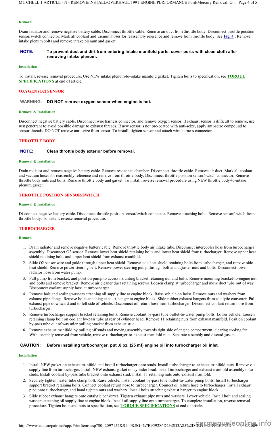
Removal
Drain radiator and remove negative battery cable. Disconnect throttle cable. Remove air duct from throttle body. Disconnect throttle position
sensor/switch connector. Mark all coolant and vacuum hoses for reassembly reference and remove from throttle body. See Fig. 4
. Remove
intake plenum bolts and remove intake plenum and gasket.
Installation
To install, reverse removal procedure. Use NEW intake plenum-to-intake manifold gasket. Tighten bolts to specification, see TORQUE
SPECIFICATIONS at end of article.
OXYGEN (O2) SENSOR
Removal & Installation
Disconnect negative battery cable. Disconnect wire harness connector, and remove oxygen sensor. If exhaust sensor is difficult to remove, use
rust penetrant to avoid possible damage to exhaust threads. If new sensor is not pre-coated with anti-seize, apply anti-seize compound to
sensor threads. DO NOT remove anti-seize from sensor. To install, tighten sensor and attach wire harness connector.
THROTTLE BODY
Removal & Installation
Drain radiator and remove negative battery cable. Remove resonance chamber. Disconnect throttle cable. Remove air duct. Mark all coolant
and vacuum hoses for reassembly reference and remove from throttle body. Disconnect throttle position sensor/switch connector. Remove
throttle body nuts and bolts. Remove throttle body and gasket. To install, reverse removal procedure using NEW throttle body-to-intake
plenum gasket.
THROTTLE POSITION SENSOR/SWITCH
Removal & Installation
Disconnect negative battery cable. Disconnect throttle position sensor/switch connector. Remove attaching bolts. Remove sensor/switch from
throttle body. To install, reverse removal procedure.
TURBOCHARGER
Removal
1. Drain radiator and remove negative battery cable. Remove throttle body air intake tube. Disconnect intercooler hose from turbocharger
assembly. Disconnect O2 sensor. Remove lower heat shield retaining bolts and lower heat shield from turbocharger. Remove upper heat
shield retaining bolts and upper heat shield from exhaust manifold.
2. Slide O2 sensor wire and guide through upper heat shield. Remove side heat shield retaining bolts from turbocharger, and remove sid e
heat shield. Remove power steering belt. Remove power steering pump through bolt and adjuster nuts and bolts. Disconnect lower
radiator hose from water pump.
3. Pull pump from bracket, and position pump to access mounting bracket retaining nut and bolts. Remove mounting bracket-to-engine nut
and bolts and remove bracket. Remove air cleaner duct retaining screws. Loosen clamp at turbocharger and move duct tube out of way.
Disconnect coolant supply hose at turbocharger.
4. Remove bolt and sealing washers attaching oil supply line at engine block. Raise vehicle on hoist. Remove nuts and washers from
exhaust pipe flange. Remove bolts attaching exhaust hanger to engine block. Slide rubber exhaust hangers from catalytic converter. Pull
exhaust pipe downward and to left side of vehicle. Disconnect oil return hose from turbocharger. Disconnect coolant return hose fro m
turbocharger.
5. Remove turbocharger support bracket retaining bolts. Remove coolant by-pass tube outlet-to-water pump bolts. Lower vehicle. Loosen
retaining clamp bolt on coolant by-pass tube at rear of cylinder head. Remove 11 retaining nuts from exhaust manifold. Position coolant
by-pass tube out of way after pulling bracket from exhaust stud.
6. Remove exhaust manifold by pulling off studs and moving assembly towards right side of engine compartment, clearing cooling fan.
With assembly removed from vehicle, remove turbocharger-to-exhaust manifold nuts. Separate assembly and discard gasket.
Installation
1. Install NEW gasket on exhaust manifold and install turbocharger onto studs. Install turbocharger-to-exhaust manifold nuts. Remo ve o il
supply line from turbocharger. Install NEW exhaust gasket on cylinder head. Install turbocharger and exhaust manifold assembly onto
studs. Install coolant by-pass tube bracket onto exhaust stud. Install 11 retaining nuts onto exhaust manifold.
2. Securely tighten heater tube clamp bolt. Raise vehicle. Install coolant by-pass tube outlet-to-water pump bolts. Install turbocharger
support bracket retaining bolts. Connect coolant return hose to turbocharger. Connect oil return hose to turbocharger. Install exhaust
pipe onto turbocharger, and hand tighten nuts and washers. Install bolts attaching exhaust hanger to engine block.
3. Slide rubber exhaust hangers onto catalytic converter. Tighten exhaust pipe nuts and washers. Lower vehicle. Install bolt and sealing
washers attaching oil supply line at engine block. Install oil supply line onto turbocharger. To complete installation, reverse removal
procedure. Tighten bolts and nuts to specification, see TORQUE SPECIFICATIONS
at end of article. NOTE:T o prevent dust and dirt from entering intake m anifold ports, cover ports with clean cloth after
rem oving intake plenum .
WARNING:DO NOT rem ove oxygen sensor when engine is hot.
NOTE:Clean throttle body exterior before rem oval.
CAUT ION: Before installing turbocharger, put .8 oz. (25 m l) engine oil into turbocharger oil inlet.
Page 4 of 5 MITCHELL 1 ARTICLE - N - REMOVE/INSTALL/OVERHAUL 1991 ENGINE PERFORMANCE Ford/Mercury Removal, O
...
3/10/2009 http://www.eautorepair.net/app/PrintItems.asp?S0=2097152&S1=0&SG=%7B959286D2%2D3A85%2D4BFC%2D9C5C%2D
...
Page 156 of 454
Back To Article
F - BASIC TESTING
1991-92 ENGINE PERFORMANCE Ford Motor Co. Basic Diagnostic Procedures
INTRODUCTION
The following diagnostic steps help prevent overlooking simple problems and begin diagnosis for a no-start condition.
The first step in diagnosing any driveability problem is to verify the complaint. Test drive the vehicle under the conditions in which the
problem reportedly occurred.
Before entering self-diagnostics, perform a careful and complete visual inspection. Most engine control problems result from mechanical
breakdowns, poor electrical connections or damaged/misrouted vacuum hoses. Before condemning the computerized system, perform each test
listed in this article.
PRELIMINARY INSPECTION & ADJUSTMENTS
VISUAL INSPECTION
Perform a visual inspection of all electrical wiring. Look for chafed, stretched, cut or pinched wiring. Ensure electrical connections fit tightly
and are not corroded. Ensure vacuum hoses are properly routed and are not cut or pinched. If necessary, see VACUUM DIAGRAMS article in
the ENGINE PERFORMANCE Section to verify routing and connections. Inspect air induction system for possible vacuum leaks.
MECHANICAL INSPECTION
Compression
Engine mechanical condition can be checked using a compression gauge, vacuum gauge or engine analyzer. See engine analyzer instruction
manual for specific instructions. Lowest compression reading must be not less than 75 percent of highest reading.
Exhaust System Backpressure
Exhaust system can be checked with a vacuum gauge or a 0-5 psi pressure gauge. If a pressure gauge is used, remove O2 sensor. Connect gauge
to O2 sensor port. Start engine, and run at 2500 RPM. If exhaust system backpressure is more than 2 psi, exhaust system or catalytic converter
is plugged.
If a vacuum gauge is used, connect it to intake manifold vacuum. Start engine. Observe vacuum gauge. Open throttle part way and hold steady.
If vacuum gauge drops slowly after stabilizing, check exhaust system for a restriction.
FUEL PRESSURE
Fuel Pressure Release
Start engine (if possible), and unplug VAF meter connector. When engine stalls, turn ignition off and reconnect VAF meter wiring. Usin g sh o p
towel, cover fitting to absorb leakage when opening fuel system.
Fuel Pressure Check
1. Connect fuel pressure gauge between fuel filter and fuel rail. Open main valve, and close drain valve. Locate fuel pump check connector
in engine compartment, near left strut. Connect jumper wire between fuel pump test terminals (Black and Green/White wires on Capri
or Black and Green/Red wires on Festiva).
2. Turn ignition on to activate fuel pump. If pump does not run, check fuel pump circuit. If possible, start engine. Measure and record fuel
pressure. For fuel pressure specifications, see FUEL PRESSURE SPECIFICATIONS
article. Disconnect vacuum from pressure
regulator. Turn engine off. Wait 5 minutes and ensure residual pressure is at least 21 psi (1.5 kg/cm
2 ).
3. Operate fuel pump by reconnecting jumper wire at fuel pump check connector. Check fuel pump performance. Pinch hose between
pressure gauge and fuel filter. Do not hold longer than necessary to check pressure.For fuel pressure specifications, see FUEL
PRESSURE SPECIFICATIONS article. If pump does not meet specifications, check fuel pump circuit, fuel pump, fuel tank and fuel
filter or replace fuel pump.
FUEL PUMP PERFORMANCE NOTE:Unless stated otherwise in test procedure, perform all voltage tests with a Digital Volt-Ohm m eter
(DVOM) with a m inim um 10-m egohm input im pedance.
CAUT ION: DO NOT use ignition switch during com pression tests on fuel injected vehicles. Fuel injectors are
triggered by ignition switch during cranking m ode. Use a rem ote starter to crank engine to prevent fire
hazard and catalytic converter and engine oiling system contam ination.
WARNING:ALWAYS relieve fuel pressure before disconnecting any fuel injection system com ponent. DO NOT
allow fuel to contact engine or electrical com ponents.
NOTE:For 1991 fuel pressure specifications, see FUEL PRESSURE SPECIFICAT IONS
article. For 1992 fuel
pressure specifications, see FUEL PRESSURE SPECIFICAT IONS
article.
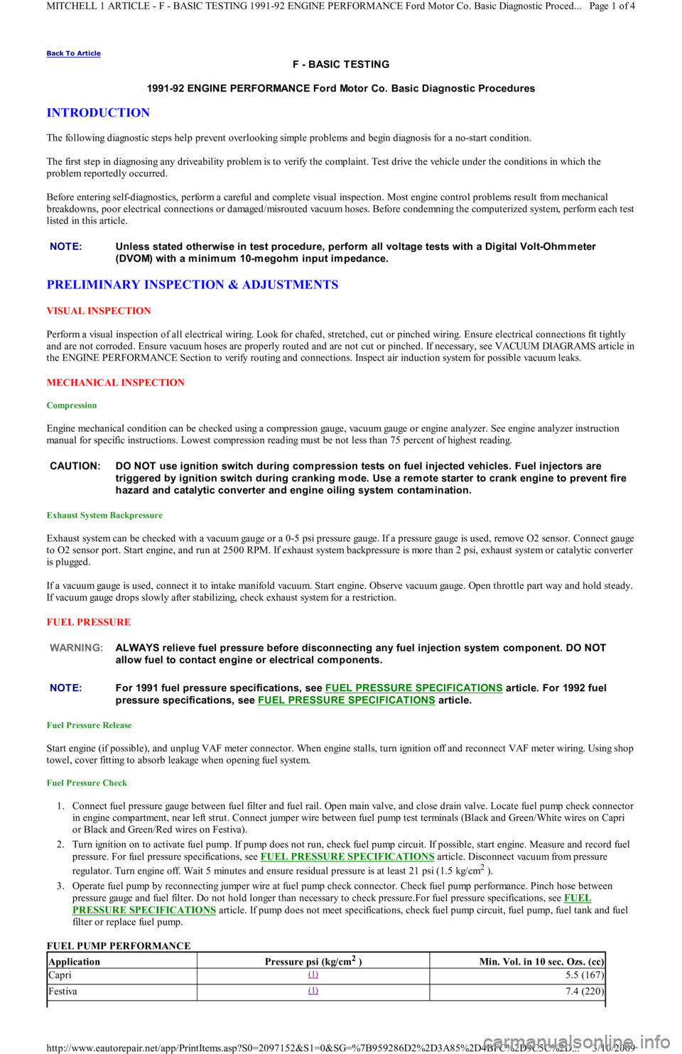
ApplicationPressure psi (kg/cm2 )Min. Vol. in 10 sec. Ozs. (cc)
Capri(1) 5.5 (167)
Festiva(1) 7.4 (220)
Page 1 of 4 MITCHELL 1 ARTICLE - F - BASIC TESTING 1991-92 ENGINE PERFORMANCE Ford Motor Co. Basic Diagnostic Proced
...
3/10/2009 http://www.eautorepair.net/app/PrintItems.asp?S0=2097152&S1=0&SG=%7B959286D2%2D3A85%2D4BFC%2D9C5C%2D
...