charging FORD FESTIVA 1991 Service Manual
[x] Cancel search | Manufacturer: FORD, Model Year: 1991, Model line: FESTIVA, Model: FORD FESTIVA 1991Pages: 454, PDF Size: 9.53 MB
Page 2 of 454
Back To Article
INST RUMENT PANEL
1991 ACCESSORIES & SAFET Y EQUIPMENT Ford Motor Co. Switches & Instrum ent Panels - Standard
DESCRIPTION & OPERATION
Instrument panel on Capri contains a speedometer, tachometer, fuel, water temperature, oil pressure and voltmeter gauges. A boost gauge is
incorporated into the tachometer on turbo models. Instrument panel is equipped with indicator/warning lights for charging system, air b ag,
manual shift, seat belt, turn signals, high beam and brakes. A CHECK ENGINE light, located on instrument panel, illuminates if a
computerized engine control fault occurs with engine running.
Instrument panel on Festiva contains a speedometer, fuel and water temperature gauges. Instrument panel is equipped with indicator/warning
lights for charging system, oil pressure, seat belt, rear defogger, turn signals, high beam and brakes. A CHECK ENGINE light, located on
instrument panel, illuminates if a computerized engine control fault occurs with engine running.
TROUBLE SHOOTING
FUEL GAUGE
Fuel Gauge Always Reads Empty
If fuel gauge always reads empty, check these items:
Check fuel gauge for open or damaged wires.
Check for open ground at fuel gauge sending unit.
Check for defective fuel sending unit.
Check for defective fuel gauge.
Check for defective instrument panel voltage regulator (Festiva).
Check for blown 10-amp METER fuse in fuse panel.
Check for open in Black/Yellow power feed wire from fuse panel instrument panel.
Check for fuel tank float full of fuel (sunk).
Fuel Gauge Always Reads Full
If fuel gauge always reads full, check these items:
Check for fuel gauge Yellow wire shorted to ground.
Check for defective fuel sending unit.
Check for defective fuel gauge.
Check for defective instrument panel voltage regulator (Festiva).
Fuel Gauge Inaccurate
If fuel gauge is inaccurate, check these items:
Check for faulty (loose or corroded) wire connections.
Check for defective fuel sending unit.
Check for defective instrument panel voltage regulator (Festiva).
TEMPERATURE GAUGE
Temperature Gauge Always Reads Cold
If temperature gauge always reads cold, check these items:
Check temperature gauge for open wire.
Check for defective temperature sender.
Check for defective temperature gauge.
Check for defective instrument panel voltage regulator (Festiva).
Check for blown 10-amp METER fuse in fuse panel.
Check for open in Black/Yellow power feed wire from fuse panel to instrument panel.
Temperature Gauge Always Reads Hot
CAUT ION: On m odels with Supplem ental Restraint System (SRS), observe safety precautions. T he air bag system
is powered directly from the battery and back-up power supply. Before any repairs are perform ed,
disconnect and shield battery ground cable. Disconnect the back-up power supply BEFORE servicing
ANY air bag com ponent. Use caution when working near steering colum n. Air bag could accidentally
deploy at any tim e.
NOTE:Ensure continuity exists between chassis ground and Black wire of instrum ent panel connector,
especially if fault exists in m ultiple gauge circuits. See appropriate chassis wiring diagram in the
WIRING DIAGRAMS Section.
Page 1 of 5 MITCHELL 1 ARTICLE - INSTRUMENT PANEL 1991 ACCESSORIES & SAFETY EQUIPMENT Ford Motor Co. Switches
...
3/10/2009 http://www.eautorepair.net/app/PrintItems.asp?S0=2097152&S1=0&SG=%7B959286D2%2D3A85%2D4BFC%2D9C5C%2D
...
Page 43 of 454
Back To Article
ALTERNATOR & REGULATOR
1991 ELECT RICAL Alternators & Regulators
DESCRIPTION
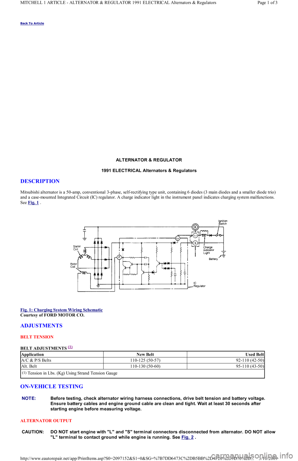
Mitsubishi alternator is a 50-amp, conventional 3-phase, self-rectifying type unit, containing 6 diodes (3 main diodes and a smaller diode trio)
and a case-mounted Integrated Circuit (IC) regulator. A charge indicator light in the instrument panel indicates charging system mal fu n ct io n s.
See Fig. 1
.
Fig. 1: Charging System Wiring Schematic
Courtesy of FORD MOTOR CO.
ADJUSTMENTS
BELT TENSION
BELT ADJUSTMENTS
(1)
ON-VEHICLE TESTING
ALTERNATOR OUTPUT
ApplicationNew BeltUsed Belt
A/C & P/S Belts110-125 (50-57)92-110 (42-50)
Alt. Belt110-130 (50-60)95-110 (43-50)
(1)Tension in Lbs. (Kg) Using Strand Tension Gauge
NOTE:Before testing, check alternator wiring harness connections, drive belt tension and battery voltage.
Ensure battery cables and engine ground cable are clean and tight. Wait at least 30 seconds after
starting engine before m easuring voltage.
CAUT ION: DO NOT start engine with "L" and "S" term inal connectors disconnected from alternator. DO NOT allow
"L" term inal to contact ground while engine is running. See Fig. 2
.
Page 1 of 3 MITCHELL 1 ARTICLE - ALTERNATOR & REGULATOR 1991 ELECTRICAL Alternators & Regulators
3/10/2009 http://www.eautorepair.net/app/PrintItems.asp?S0=2097152&S1=0&SG=%7B7DD6473C%2DB5BB%2D4F20%2D9D70%2D
...
Page 49 of 454
Back To Article
FUSES & CIRCUIT BREAKERS
Fuses & Circuit Breakers 1988-93 Festiva
FUSES & FUSIBLE LINKS
FUSE PANEL & FUSIBLE LINK BLOCK LOCATIONS
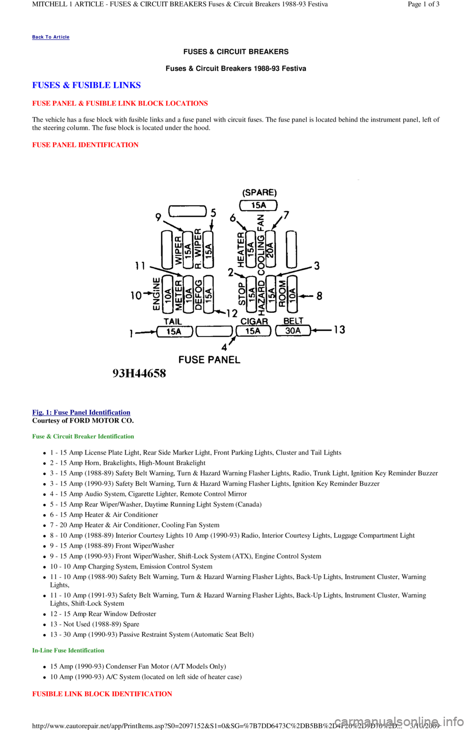
The vehicle has a fuse block with fusible links and a fuse panel with circuit fuses. The fuse panel is located behind the instrument panel, left o
f
the steering column. The fuse block is located under the hood.
FUSE PANEL IDENTIFICATION
Fig. 1: Fuse Panel Identification
Courtesy of FORD MOTOR CO.
Fuse & Circuit Breaker Identification
1 - 15 Amp License Plate Light, Rear Side Marker Ligh t , Fr o n t P a r kin g Ligh t s, C l u st e r a n d Ta il Ligh t s
2 - 15 Amp Horn, Brakelights, High-Mount Brakelight
3 - 15 Amp (1988-89) Safety Belt Warning, Turn & Hazard Warning Flasher Lights, Radio, Trunk Light, Ignition Key Reminder Buzzer
3 - 15 Amp (1990-93) Safety Belt Warning, Turn & Hazard Warning Flasher Lights, Ignition Key Reminder Buzzer
4 - 15 Amp Audio System, Cigarette Lighter, Remote Control Mirror
5 - 15 Amp Rear Wiper/Washer, Daytime Running Light System (Canada)
6 - 15 Amp Heater & Air Conditioner
7 - 20 Amp Heater & Air Conditioner, Cooling Fan System
8 - 10 Amp (1988-89) Interior Courtesy Lights 10 Amp (1990-93) Radio, Interior Courtesy Lights, Luggage Compartment Light
9 - 15 Amp (1988-89) Front Wiper/Washer
9 - 15 Amp (1990-93) Front Wiper/Washer, Shift-Lock System (ATX), Engine Control System
10 - 10 Amp Charging System, Emission Control System
11 - 10 Amp (1988-90) Safety Belt Warning, Turn & Hazard Warning Flasher Lights, Back-Up Lights, Instrument Cluster, Warning
Lights,
11 - 10 Amp (1991-93) Safety Belt Warning, Turn & Hazard Warning Flasher Lights, Back-Up Lights, Instrument Cluster, Warning
Lights, Shift-Lock System
12 - 15 Amp Rear Window Defroster
13 - Not Used (1988-89) Spare
13 - 30 Amp (1990-93) Passive Restraint System (Automatic Seat Belt)
In-Line Fuse Identification
15 Amp (1990-93) Condenser Fan Motor (A/T Models Only)
10 Amp (1990-93) A/C System (located on left side of heater case)
FUSIBLE LINK BLOCK IDENTIFICATION
Page 1 of 3 MITCHELL 1 ARTICLE - FUSES & CIRCUIT BREAKERS Fuses & Circuit Breakers 1988-93 Festiva
3/10/2009 http://www.eautorepair.net/app/PrintItems.asp?S0=2097152&S1=0&SG=%7B7DD6473C%2DB5BB%2D4F20%2D9D70%2D
...
Page 50 of 454
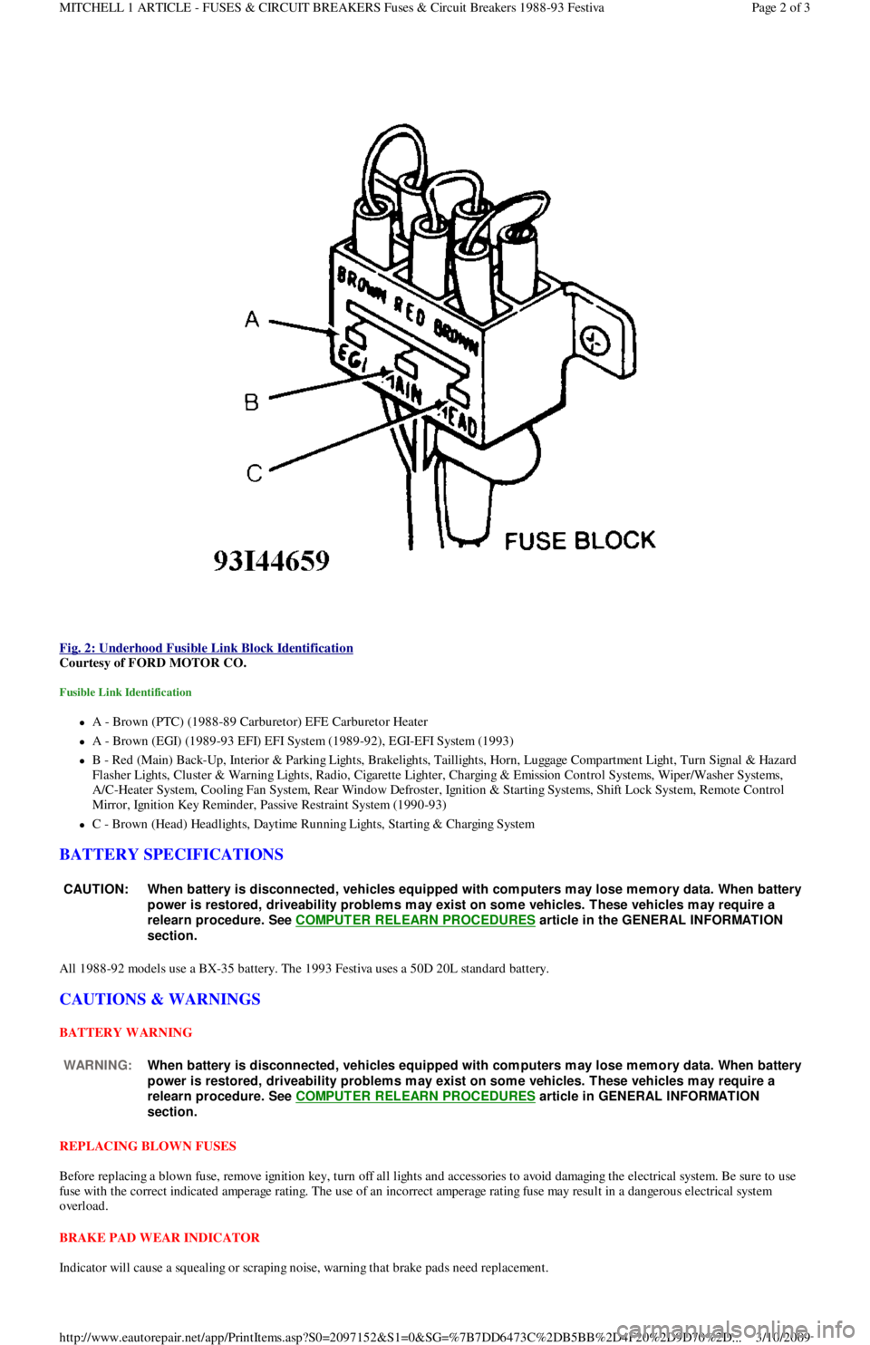
Fig. 2: Underhood Fusible Link Block Identification
Courtesy of FORD MOTOR CO.
Fusible Link Identification
A - Brown (PTC) (1988-89 Carburetor) EFE Carburetor Heater
A - Brown (EGI) (1989-93 EFI) EFI System (1989-92), EGI-EFI System (1993)
B - Red (Main) Back-Up, Interior & Parking Lights, Brakelights, Taillights, Horn, Luggage Compartment Light, Turn Signal & Hazard
F l a sh e r Ligh t s, C l u st e r & Wa r n in g Ligh t s, R a d io , C iga r e t t e Ligh t e r , C h a r gin g & E missio n C o n t r o l S yst e ms, Wip e r / Wa sh e r S yst e ms,
A/C-Heater System, Cooling Fan System, Rear Window Defroster, Ignition & Starting Systems, Shift Lock System, Remote Control
Mirror, Ignition Key Reminder, Passive Restraint System (1990-93)
C - Brown (Head) Headlights, Daytime Running Lights, Starting & Charging System
BATTERY SPECIFICATIONS
All 1988-92 models use a BX-35 battery. The 1993 Festiva uses a 50D 20L standard battery.
CAUTIONS & WARNINGS
BATTERY WARNING
REPLACING BLOWN FUSES
Before replacing a blown fuse, remove ignition key, turn off all lights and accessories to avoid damaging the electrical system. Be sure to use
fuse with the correct indicated amperage rating. The use of an incorrect amperage rating fuse may result in a dangerous electrical system
overload.
BRAKE PAD WEAR INDICATOR
Indicator will cause a squealing or scraping noise, warning that brake pads need replacement.
CAUT ION: When battery is disconnected, vehicles equipped with com puters m ay lose m em ory data. When battery
power is restored, driveability problem s m ay exist on som e vehicles. T hese vehicles m ay require a
relearn procedure. See COMPUTER RELEARN PROCEDURES
article in the GENERAL INFORMAT ION
section.
WARNING:When battery is disconnected, vehicles equipped with com puters m ay lose m em ory data. When battery
power is restored, driveability problem s m ay exist on som e vehicles. T hese vehicles m ay require a
relearn procedure. See COMPUTER RELEARN PROCEDURES
article in GENERAL INFORMAT ION
section.
Page 2 of 3 MITCHELL 1 ARTICLE - FUSES & CIRCUIT BREAKERS Fuses & Circuit Breakers 1988-93 Festiva
3/10/2009 http://www.eautorepair.net/app/PrintItems.asp?S0=2097152&S1=0&SG=%7B7DD6473C%2DB5BB%2D4F20%2D9D70%2D
...
Page 60 of 454
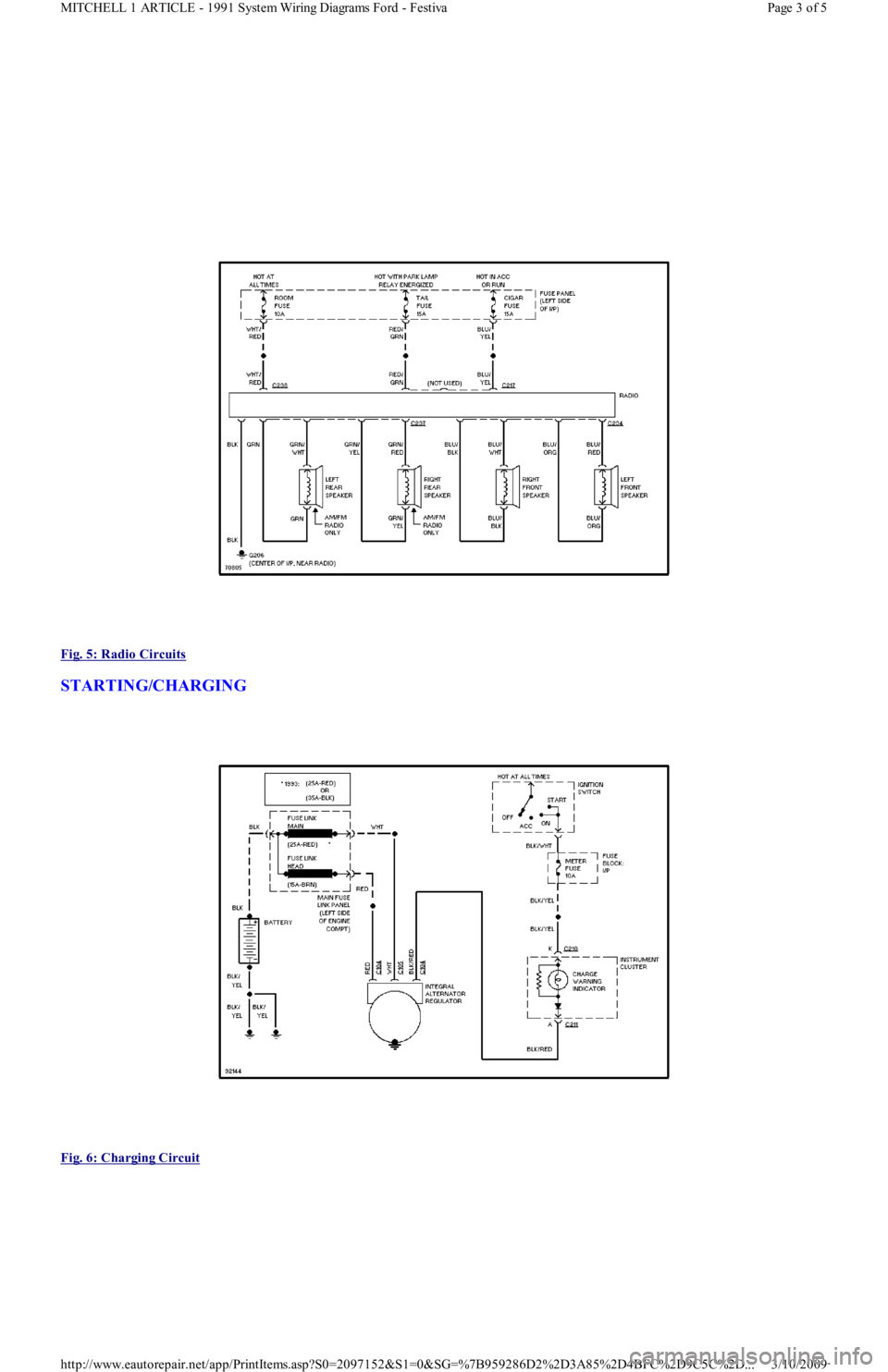
Fig. 5: Radio Circuits
STARTING/CHARGING
Fig. 6: Charging Circuit
Page 3 of 5 MITCHELL 1 ARTICLE - 1991 System Wiring Diagrams Ford - Festiva
3/10/2009 http://www.eautorepair.net/app/PrintItems.asp?S0=2097152&S1=0&SG=%7B959286D2%2D3A85%2D4BFC%2D9C5C%2D
...
Page 63 of 454
Back To Article
GENERAL INFORMATION
Using Mitchell1's Wiring Diagram s
INTRODUCTION
Mitchell1(R) obtains wiring diagrams and technical service bulletins, containing wiring diagram changes, from the domestic and import
manufacturers. These are checked for accuracy and are all redrawn into a consistent format for easy use. All system wiring diagrams are
available in color format and may be viewed and or printed in color or black and white, depending on your program settings and available
printer hardware.
In the past, when cars were simpler, diagrams were simpler. All components were connected by wires, and diagrams seldom exceeded 4 pages
in length. Today, some wiring diagrams require more than 16 pages. It would be impractical to expect a service technician to trace a wire from
page 1 across every page to page 16.
Removing some of the wiring maze reduces eyestrain and time wasted searching across several pages. Today, the majority of Mitchell1(R)
diagrams follow a much improved format, which permits space for internal switch details, and component and ground locations.
Components shown with a dashed line instead of a solid line indicate not all circuits are shown in this particular diagram (circuits shown in
system diagrams are typically applicable to that system only). The remaining circuits connected to that component will be shown in the
appropriate system that they apply to.
Today, the wiring diagram necessary to support a given repair procedure is included within that article or a link is provided to the appropriate
SYSTEM WIRING DIAGRAM article. For example, the wiring diagram for a Ford EEC-IV system may be included in ENGINE
PERFORMANCE and WIRING DIAGRAMS articles for Ford Motor Co. The wiring diagram for a cruise control system may be included in
ACCESSORIES & EQUIPMENT section for the specific vehicle manufacturer, and the wiring diagram for an anti-lock brake system may be
included in BRAKES and WIRING DIAGRAMS for the specific manufacturer.
WIRING DIAGRAMS contains all wiring diagrams not included in STARTING & CHARGING SYSTEMS and ACCESSORIES &
EQUIPMENT. This includes: Data Link Connectors, Ground Distribution, Power Distribution, Engine Performance, Electric Cooling Fans,
Anti-Lock Brakes, Electronic Suspension and Electronic Steering wiring diagrams. The Data Link Connectors wiring diagrams show the
circuits by which the various on-board computers exchange information, and the diagnostic connectors used for diagnosis and their location.
The Ground Distribution wiring diagrams show all vehicle ground points, their location, and the components common to those ground points.
The Power Distribution wiring diagrams show the power feed circuits and the components common to those power feeds.
Wiring diagrams used to support the information in ACCESSORIES & EQUIPMENT are drawn in a "top-down" format. The diagrams are
drawn with the power source at the top of the diagram and the ground point at the bottom of the diagram. Component locations are identified
on the wiring diagrams. Any wires that do not connect directly to a component are identified on the diagram to indicate where they go.
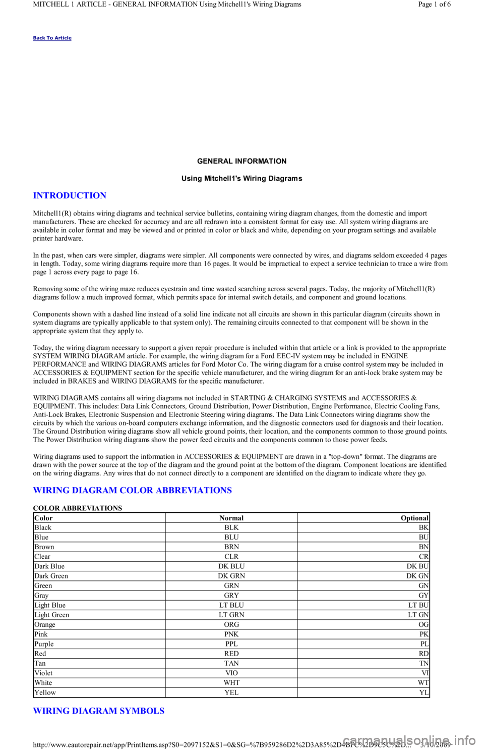
WIRING DIAGRAM COLOR ABBREVIATIONS
COLOR ABBREVIATIONS
WIRING DIAGRAM SYMBOLS
ColorNormalOptional
BlackBLKBK
BlueBLUBU
BrownBRNBN
ClearCLRCR
Dark BlueDK BLUDK BU
Dark GreenDK GRNDK GN
GreenGRNGN
GrayGRYGY
Light BlueLT BLULT BU
Light GreenLT GRNLT GN
OrangeORGOG
PinkPNKPK
PurplePPLPL
RedREDRD
TanTANTN
VioletVIOVI
WhiteWHTWT
YellowYELYL
Page 1 of 6 MITCHELL 1 ARTICLE - GENERAL INFORMATION Using Mitchell1's Wiring Diagrams
3/10/2009 http://www.eautorepair.net/app/PrintItems.asp?S0=2097152&S1=0&SG=%7B959286D2%2D3A85%2D4BFC%2D9C5C%2D
...
Page 142 of 454
Back To Article
J - PIN VOLT AGE CHART S
1991 ENGINE PERFORMANCE Ford/Mercury Pin Voltage Charts
INTRODUCTION
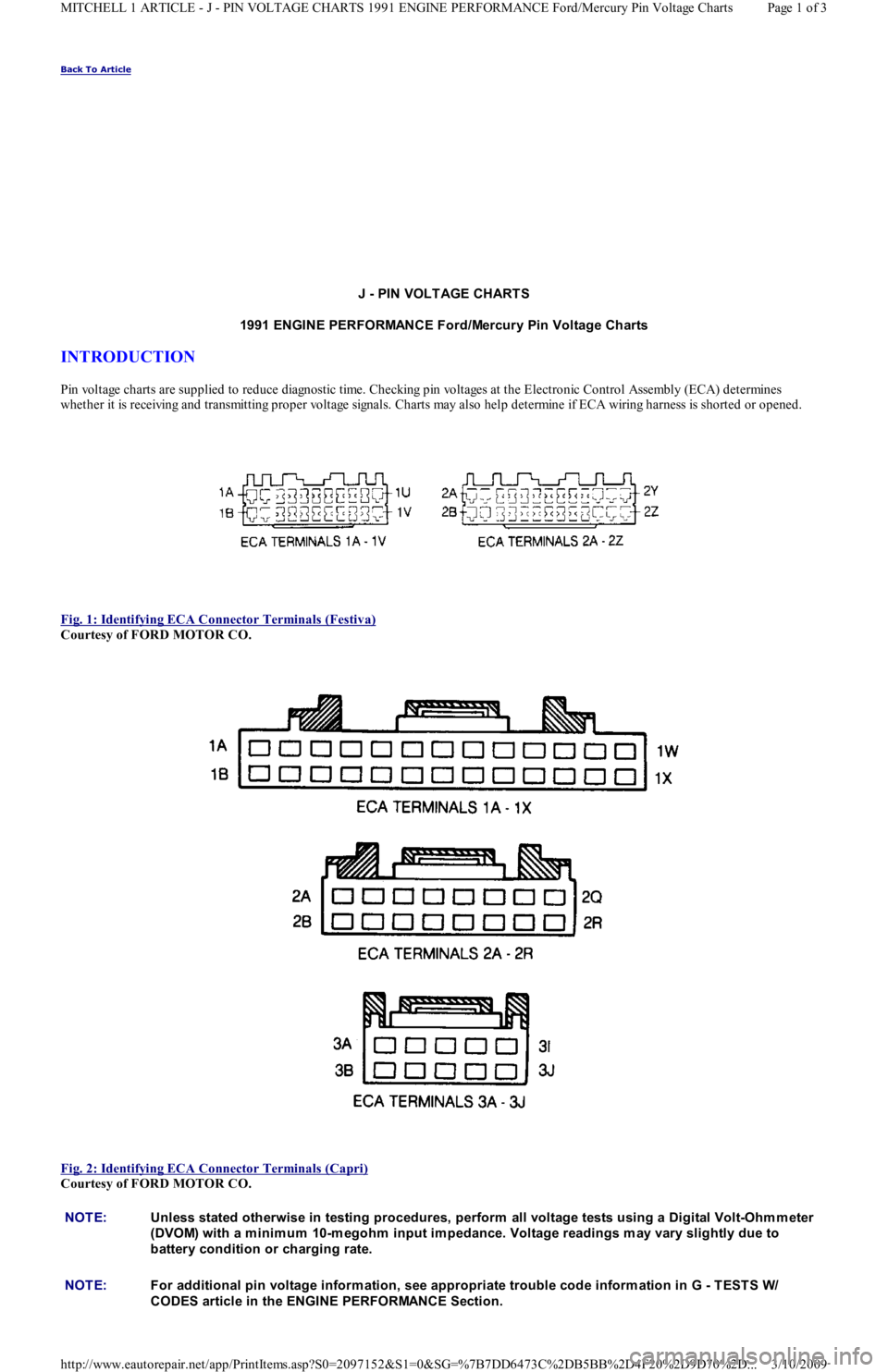
Pin voltage charts are supplied to reduce diagnostic time. Checking pin voltages at the Electronic Control Assembly (ECA) determin es
whether it is receiving and transmitting proper voltage signals. Charts may also help determine if ECA wiring harness is shorted or opened.
Fig. 1: Identifying ECA Connector Terminals (Festiva)
Courtesy of FORD MOTOR CO.
Fig. 2: Identifying ECA Connector Terminals (Capri)
Courtesy of FORD MOTOR CO.
NOTE:Unless stated otherwise in testing procedures, perform all voltage tests using a Digital Volt-Ohm m eter
(DVOM) with a m inim um 10-m egohm input im pedance. Voltage readings m ay vary slightly due to
battery condition or charging rate.
NOTE:For additional pin voltage inform ation, see appropriate trouble code inform ation in G - T EST S W/
CODES article in the ENGINE PERFORMANCE Section.
Page 1 of 3 MITCHELL 1 ARTICLE - J - PIN VOLTAGE CHARTS 1991 ENGINE PERFORMANCE Ford/Mercury Pin Voltage Charts
3/10/2009 http://www.eautorepair.net/app/PrintItems.asp?S0=2097152&S1=0&SG=%7B7DD6473C%2DB5BB%2D4F20%2D9D70%2D
...
Page 214 of 454
Back To Article
GENERAL INFORMATION
T rouble Shooting - Basic Procedures
* PLEASE READ THIS FIRST *
ACCESSORIES & ELECTRICAL
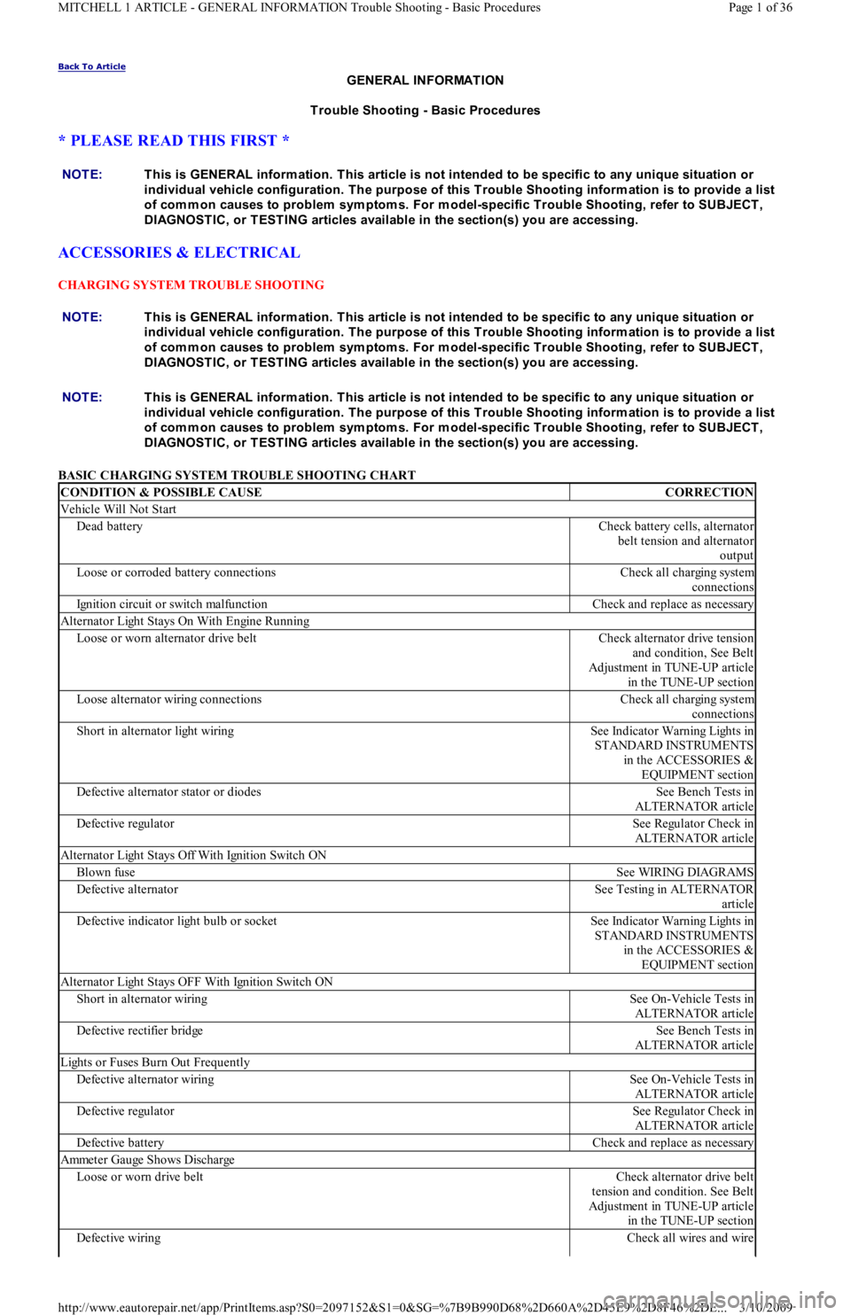
CHARGING SYSTEM TROUBLE SHOOTING
BASIC CHARGING SYSTEM TROUBLE SHOOTING CHART NOTE:This is GENERAL inform ation. This article is not intended to be specific to any unique situation or
individual vehicle configuration. T he purpose of this T rouble Shooting inform ation is to provide a list
of com m on causes to problem sym ptom s. For m odel-specific T rouble Shooting, refer to SUBJECT ,
DIAGNOST IC, or T EST ING articles available in the section(s) you are accessing.
NOTE:This is GENERAL inform ation. This article is not intended to be specific to any unique situation or
individual vehicle configuration. T he purpose of this T rouble Shooting inform ation is to provide a list
of com m on causes to problem sym ptom s. For m odel-specific T rouble Shooting, refer to SUBJECT ,
DIAGNOST IC, or T EST ING articles available in the section(s) you are accessing.
CONDITION & POSSIBLE CAUSECORRECTION
Vehicle Will Not Start
Dead batteryCheck battery cells, alternator
belt tension and alternator
output
Loose or corroded battery connectionsCheck all charging system
connections
Ignition circuit or switch malfunctionCheck and replace as necessary
Alternator Light Stays On With Engine Running
Loose or worn alternator drive beltCheck alternator drive tension
and condition, See Belt
Adjustment in TUNE-UP article
in the TUNE-UP section
Loose alternator wiring connectionsCheck all charging system
connections
Short in alternator light wiringSee Indicator Warning Lights in
STANDARD INSTRUMENTS
in the ACCESSORIES &
EQUIPMENT section
Defective alternator stator or diodesSee Bench Tests in
ALTERNATOR article
Defective regulatorSee Regulator Check in
ALTERNATOR article
Alternator Light Stays Off With Ignition Switch ON
Blown fuseSee WIRING DIAGRAMS
Defective alternatorSee Testing in ALTERNATOR
article
Defective indicator light bulb or socketSee Indicator Warning Lights in
STANDARD INSTRUMENTS
in the ACCESSORIES &
EQUIPMENT section
Alternator Light Stays OFF With Ignition Switch ON
Short in alternator wiringSee On-Vehicle Tests in
ALTERNATOR article
Defective rectifier bridgeSee Bench Tests in
ALTERNATOR article
Lights or Fuses Burn Out Frequently
Defective alternator wiringSee On-Vehicle Tests in
ALTERNATOR article
Defective regulatorSee Regulator Check in
ALTERNATOR article
Defective batteryCheck and replace as necessary
Ammeter Gauge Shows Discharge
Loose or worn drive beltCheck alternator drive belt
tension and condition. See Belt
Adjustment in TUNE-UP article
in the TUNE-UP section
Defective wiringCheck all wires and wire
Page 1 of 36 MITCHELL 1 ARTICLE - GENERAL INFORMATION Trouble Shooting - Basic Procedures
3/10/2009 http://www.eautorepair.net/app/PrintItems.asp?S0=2097152&S1=0&SG=%7B9B990D68%2D660A%2D45E9%2D8F46%2DE
...
Page 215 of 454
IGNITION SYSTEM TROUBLE SHOOTING
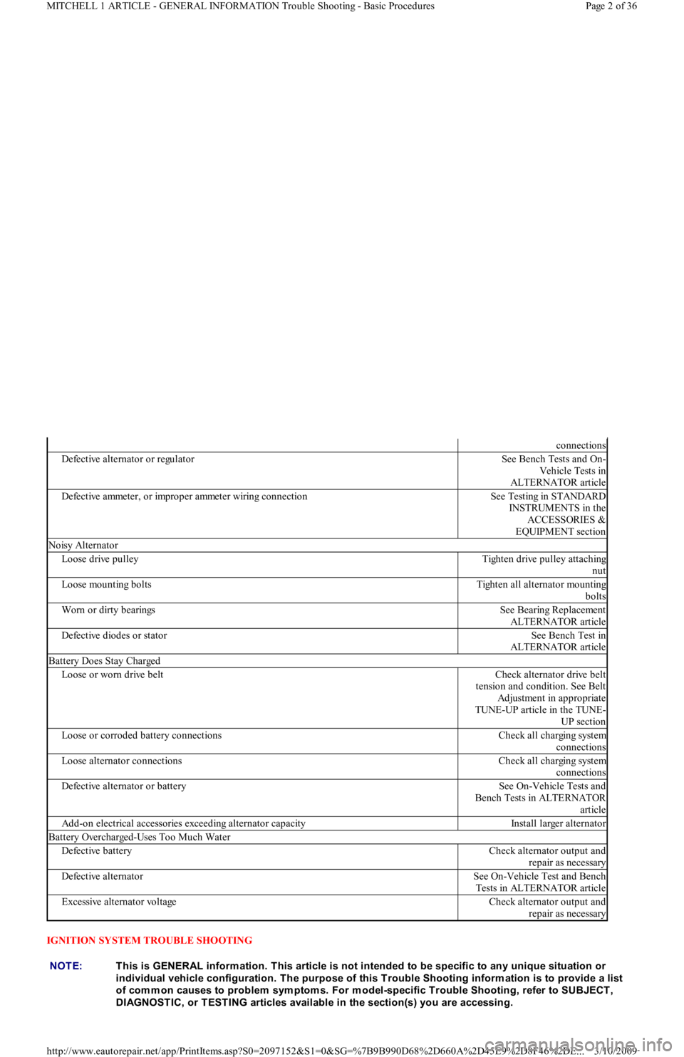
connections
Defective alternator or regulatorSee Bench Tests and On-
Vehicle Tests in
ALTERNATOR article
Defective ammeter, or improper ammeter wiring connectionSee Testing in STANDARD
INSTRUMENTS in the
ACCESSORIES &
EQUIPMENT section
Noisy Alternator
Loose drive pulleyTighten drive pulley attaching
nut
Loose mounting boltsTighten all alternator mounting
bolts
Worn or dirty bearingsSee Bearing Replacement
ALTERNATOR article
Defective diodes or statorSee Bench Test in
ALTERNATOR article
Battery Does Stay Charged
Loose or worn drive beltCheck alternator drive belt
tension and condition. See Belt
Adjustment in appropriate
TUNE-UP article in the TUNE-
UP section
Loose or corroded battery connectionsCheck all charging system
connections
Loose alternator connectionsCheck all charging system
connections
Defective alternator or batterySee On-Vehicle Tests and
Bench Tests in ALTERNATOR
article
Add-on electrical accessories exceeding alternator capacityInstall larger alternator
Battery Overcharged-Uses Too Much Water
Defective batteryCheck alternator output and
repair as necessary
Defective alternatorSee On-Vehicle Test and Bench
Tests in ALTERNATOR article
Excessive alternator voltageCheck alternator output and
repair as necessary
NOTE:This is GENERAL inform ation. This article is not intended to be specific to any unique situation or
individual vehicle configuration. T he purpose of this T rouble Shooting inform ation is to provide a list
of com m on causes to problem sym ptom s. For m odel-specific T rouble Shooting, refer to SUBJECT ,
DIAGNOST IC, or T EST ING articles available in the section(s) you are accessing.
Page 2 of 36 MITCHELL 1 ARTICLE - GENERAL INFORMATION Trouble Shooting - Basic Procedures
3/10/2009 http://www.eautorepair.net/app/PrintItems.asp?S0=2097152&S1=0&SG=%7B9B990D68%2D660A%2D45E9%2D8F46%2DE
...
Page 306 of 454
Back To Article
1991 GENERAL SERVICING
A/C Com pressor Refrigerant Oil Checking
ISOLATING COMPRESSOR
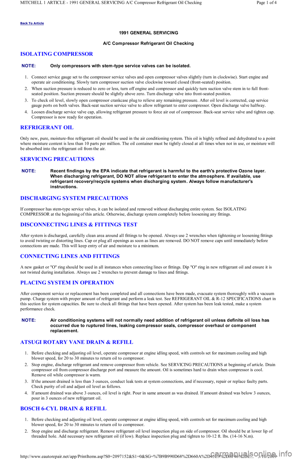
1. Connect service gauge set to the compressor service valves and open compressor valves slightly (turn in clockwise). Start engine and
operate air conditioning. Slowly turn compressor suction valve clockwise toward closed (front-seated) position.
2. When suction pressure is reduced to zero or less, turn off engine and compressor and quickly turn suction valve stem in to full front-
seated position. Suction pressure should be slightly above zero. Turn discharge valve into front-seated position.
3. To check oil level, slowly open compressor crankcase plug to relieve any remaining pressure. After oil level is corrected, cap service
gauge ports on both valves. Back-seat suction service valve to allow refrigerant to enter compressor. Open discharge valve halfway.
4. Loosen discharge service valve cap, allowing refrigerant pressure to force air out of compressor. Back-seat service valve and tighten cap.
Compressor is now ready for operation.
REFRIGERANT OIL
Only new, pure, moisture-free refrigerant oil should be used in the air conditioning system. This oil is highly refined and dehydrated to a point
where moisture content is less than 10 parts per million. The oil container must be tightly closed at all times when not in use, or moisture will
be absorbed into the refrigerant oil from the air.
SERVICING PRECAUTIONS
DISCHARGING SYSTEM PRECAUTIONS
If compressor has stem-type service valves, it can be isolated and removed without discharging entire system. See ISOLATING
COMPRESSOR at the beginning of this article. Otherwise, discharge system completely before loosening any fittings.
DISCONNECTING LINES & FITTINGS TEST
After system is discharged, carefully clean area around all fittings to be opened. Always use 2 wrenches when tightening or loosening fittings
to avoid twisting or distorting lines. Cap or plug all openings as soon as lines are removed. DO NOT remove caps until immediately before
connections are made. This will keep entry of air and moisture to a minimum.
CONNECTING LINES AND FITTINGS
A new gasket or "O" ring should be used in all instances when connecting lines or fittings. Dip "O" ring in new refrigerant oil and ensure it is
not twisted during installation. Always use 2 wrenches to prevent damage to lines and fittings.
PLACING SYSTEM IN OPERATION
After component service or replacement has been completed and all connections have been made, evacuate system thoroughly with a vacuum
pump. Charge system with proper amount of refrigerant and perform a leak test. See REFRIGERANT OIL & R-12 SPECIFICATIONS chart in
this section for system capacities. Be sure to check all fittings that have been opened. After system has been leak tested, make a system
performance check.
ATSUGI ROTARY VANE DRAIN & REFILL
1. Before checking and adjusting oil level, operate compressor at engine idling speed, with controls set for maximum cooling and high
blower speed, for 20 to 30 minutes to return oil to compressor.
2. Stop engine, discharge refrigerant and remove compressor from vehicle. See SERVICING PRECAUTIONS at beginning of article. Drain
compressor oil from compressor discharge port and measure the amount. Oil is sometimes hard to drain when compressor is cool.
Remove oil while compressor is warm.
3. If the amount drained is less than 3 ounces, conduct leak tests at system connections, and if necessary, repair or replace faulty parts.
Check purity of oil and adjust oil level as follows.
4. If amount drained was above 3 ounces, oil level is right. Pour in same amount as was drained. If amount drained was below 3 ounces,
pour in 3 ounces of new refrigerant oil.
BOSCH 6-CYL DRAIN & REFILL
1. Before checking and adjusting oil level, operate compressor at engine idling speed, with controls set for maximum cooling and high
blower speed, for 20 to 30 minutes to return oil to compressor.
2. Stop engine and discharge refrigerant. Remove refrigerant oil level inspection plug on side of compressor. Oil should be at lower lip of
threaded hole. Add necessary new refrigerant oil (if low). Replace inspection plug and tighten to 10-12 ft. lbs. (14-16 N.m). NOTE:Only com pressors with stem -type service valves can be isolated.
NOTE:Recent findings by the EPA indicate that refrigerant is harm ful to the earth's protective Ozone layer.
When discharging refrigerant, DO NOT allow refrigerant to enter the atm osphere. If available, use
refrigerant recovery/recycle system s when discharging system . Always follow m anufacturer's
instructions.
NOTE:Air conditioning system s will not norm ally need addition of refrigerant oil unless definite oil loss has
occurred due to ruptured lines, leaking com pressor seals, com pressor overhaul or com ponent
replacem ent.
Page 1 of 4 MITCHELL 1 ARTICLE - 1991 GENERAL SERVICING A/C Compressor Refrigerant Oil Checking
3/10/2009 http://www.eautorepair.net/app/PrintItems.asp?S0=2097152&S1=0&SG=%7B9B990D68%2D660A%2D45E9%2D8F46%2DE
...