oil temperature FORD FESTIVA 1991 Service Manual
[x] Cancel search | Manufacturer: FORD, Model Year: 1991, Model line: FESTIVA, Model: FORD FESTIVA 1991Pages: 454, PDF Size: 9.53 MB
Page 2 of 454
Back To Article
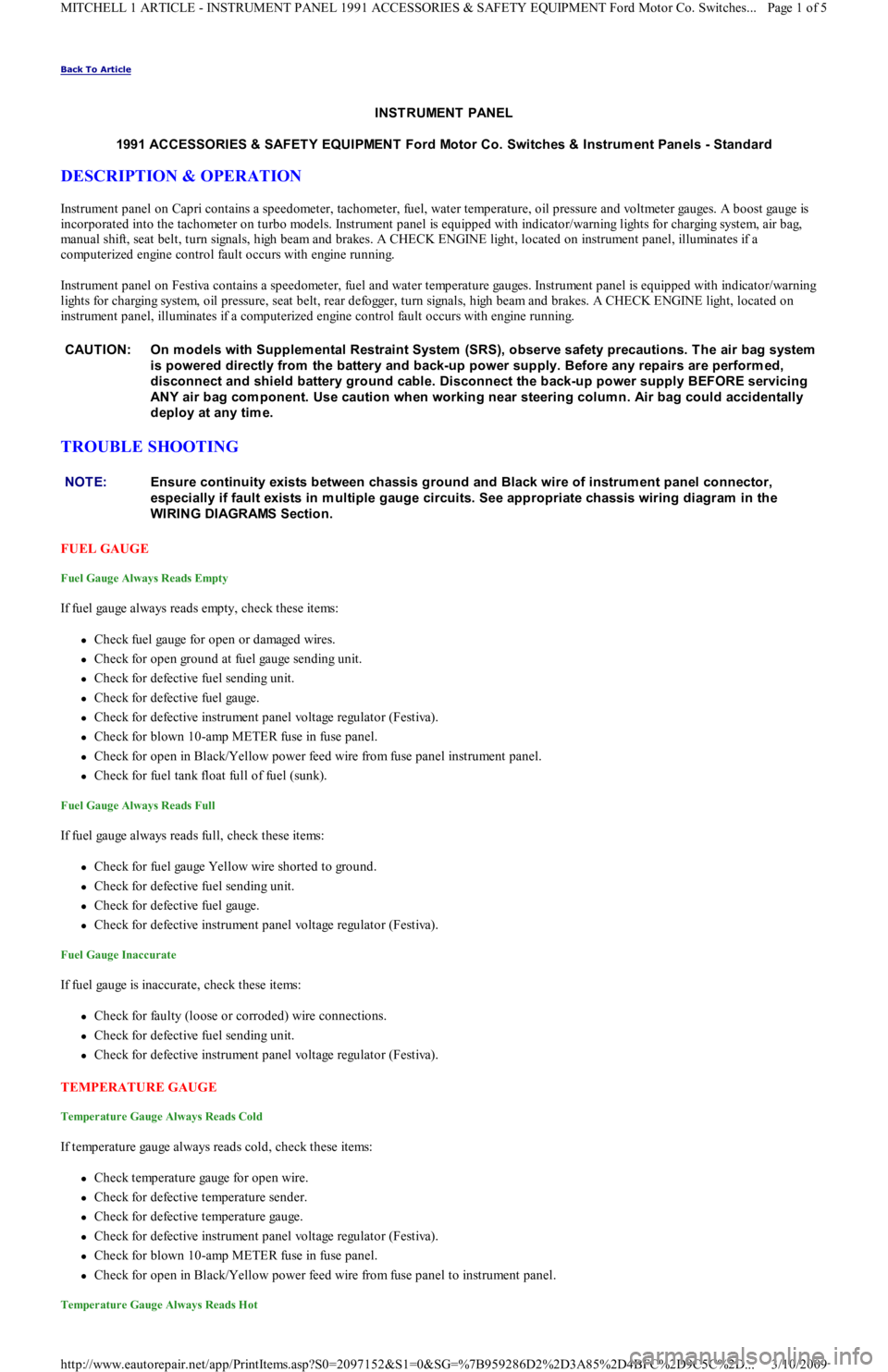
INST RUMENT PANEL
1991 ACCESSORIES & SAFET Y EQUIPMENT Ford Motor Co. Switches & Instrum ent Panels - Standard
DESCRIPTION & OPERATION
Instrument panel on Capri contains a speedometer, tachometer, fuel, water temperature, oil pressure and voltmeter gauges. A boost gauge is
incorporated into the tachometer on turbo models. Instrument panel is equipped with indicator/warning lights for charging system, air b ag,
manual shift, seat belt, turn signals, high beam and brakes. A CHECK ENGINE light, located on instrument panel, illuminates if a
computerized engine control fault occurs with engine running.
Instrument panel on Festiva contains a speedometer, fuel and water temperature gauges. Instrument panel is equipped with indicator/warning
lights for charging system, oil pressure, seat belt, rear defogger, turn signals, high beam and brakes. A CHECK ENGINE light, located on
instrument panel, illuminates if a computerized engine control fault occurs with engine running.
TROUBLE SHOOTING
FUEL GAUGE
Fuel Gauge Always Reads Empty
If fuel gauge always reads empty, check these items:
Check fuel gauge for open or damaged wires.
Check for open ground at fuel gauge sending unit.
Check for defective fuel sending unit.
Check for defective fuel gauge.
Check for defective instrument panel voltage regulator (Festiva).
Check for blown 10-amp METER fuse in fuse panel.
Check for open in Black/Yellow power feed wire from fuse panel instrument panel.
Check for fuel tank float full of fuel (sunk).
Fuel Gauge Always Reads Full
If fuel gauge always reads full, check these items:
Check for fuel gauge Yellow wire shorted to ground.
Check for defective fuel sending unit.
Check for defective fuel gauge.
Check for defective instrument panel voltage regulator (Festiva).
Fuel Gauge Inaccurate
If fuel gauge is inaccurate, check these items:
Check for faulty (loose or corroded) wire connections.
Check for defective fuel sending unit.
Check for defective instrument panel voltage regulator (Festiva).
TEMPERATURE GAUGE
Temperature Gauge Always Reads Cold
If temperature gauge always reads cold, check these items:
Check temperature gauge for open wire.
Check for defective temperature sender.
Check for defective temperature gauge.
Check for defective instrument panel voltage regulator (Festiva).
Check for blown 10-amp METER fuse in fuse panel.
Check for open in Black/Yellow power feed wire from fuse panel to instrument panel.
Temperature Gauge Always Reads Hot
CAUT ION: On m odels with Supplem ental Restraint System (SRS), observe safety precautions. T he air bag system
is powered directly from the battery and back-up power supply. Before any repairs are perform ed,
disconnect and shield battery ground cable. Disconnect the back-up power supply BEFORE servicing
ANY air bag com ponent. Use caution when working near steering colum n. Air bag could accidentally
deploy at any tim e.
NOTE:Ensure continuity exists between chassis ground and Black wire of instrum ent panel connector,
especially if fault exists in m ultiple gauge circuits. See appropriate chassis wiring diagram in the
WIRING DIAGRAMS Section.
Page 1 of 5 MITCHELL 1 ARTICLE - INSTRUMENT PANEL 1991 ACCESSORIES & SAFETY EQUIPMENT Ford Motor Co. Switches
...
3/10/2009 http://www.eautorepair.net/app/PrintItems.asp?S0=2097152&S1=0&SG=%7B959286D2%2D3A85%2D4BFC%2D9C5C%2D
...
Page 3 of 454
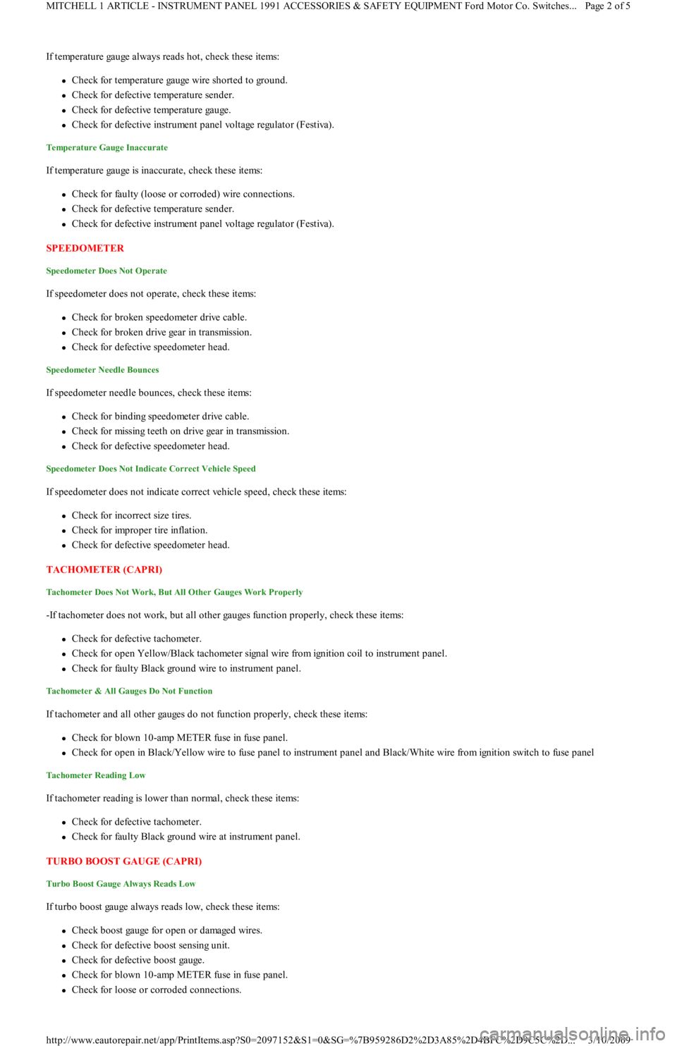
If temperature gauge always reads hot, check these items:
Check for temperature gauge wire shorted to ground.
Check for defective temperature sender.
Check for defective temperature gauge.
Check for defective instrument panel voltage regulator (Festiva).
Temperature Gauge Inaccurate
If temperature gauge is inaccurate, check these items:
Check for faulty (loose or corroded) wire connections.
Check for defective temperature sender.
Check for defective instrument panel voltage regulator (Festiva).
SPEEDOMETER
Speedometer Does Not Operate
If speedometer does not operate, check these items:
Check for broken speedometer drive cable.
Check for broken drive gear in transmission.
Check for defective speedometer head.
Speedometer Needle Bounces
If speedometer needle bounces, check these items:
Check for binding speedometer drive cable.
Check for missing teeth on drive gear in transmission.
Check for defective speedometer head.
Speedometer Does Not Indicate Correct Vehicle Speed
If speedometer does not indicate correct vehicle speed, check these items:
Check for incorrect size tires.
Check for improper tire inflation.
Check for defective speedometer head.
TACHOMETER (CAPRI)
Tachometer Does Not Work, But All Other Gauges Work Properly
-If tachometer does not work, but all other gauges function properly, check these items:
Check for defective tachometer.
Check for open Yellow/Black tachometer signal wire from ignition coil to instrument panel.
Check for faulty Black ground wire to instrument panel.
Tachometer & All Gauges Do Not Function
If tachometer and all other gauges do not function properly, check these items:
Check for blown 10-amp METER fuse in fuse panel.
Check for open in Black/Yellow wire to fuse panel to instrument panel and Black/White wire from ignition switch to fuse panel
Tachometer Reading Low
If tachometer reading is lower than normal, check these items:
Check for defective tachometer.
Check for faulty Black ground wire at instrument panel.
TURBO BOOST GAUGE (CAPRI)
Turbo Boost Gauge Always Reads Low
If turbo boost gauge always reads low, check these items:
Check boost gauge for open or damaged wires.
Check for defective boost sensing unit.
Check for defective boost gauge.
Check for blown 10-amp METER fuse in fuse panel.
Check for loose or corroded connections.
Page 2 of 5 MITCHELL 1 ARTICLE - INSTRUMENT PANEL 1991 ACCESSORIES & SAFETY EQUIPMENT Ford Motor Co. Switches
...
3/10/2009 http://www.eautorepair.net/app/PrintItems.asp?S0=2097152&S1=0&SG=%7B959286D2%2D3A85%2D4BFC%2D9C5C%2D
...
Page 4 of 454
Turbo Boost Gauge Always Reads High
If turbo boost gauge always reads high, check these items:
Check for damaged White/Black signal wire.
Check for defective boost sensing unit.
Check for defective boost gauge.
Turbo Boost Gauge Inaccurate
If turbo boost gauge is inaccurate, check these items:
Check for loose or corroded connections.
Check for defective boost sensing unit.
Check for defective boost gauge.
TESTING
FUEL GAUGE SENDING UNIT
Capri
Remove rear seat cushion. Disconnect fuel pump/fuel gauge sending unit electrical connector at access cover. Turn ignition on. Fuel gauge
should read empty. Using a jumper wire, connect Yellow fuel gauge wire of vehicle harness connector to ground. Fuel gauge should read full.
If fuel gauge operates as specified, replace fuel gauge sending unit.
Festiva
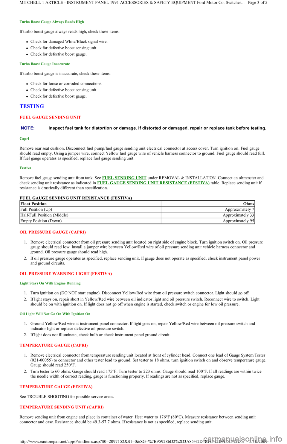
Remove fuel gauge sending unit from tank. See FUEL SENDING UNIT under REMOVAL & INSTALLATION. Connect an ohmmeter and
check sending unit resistance as indicated in FUEL GAUGE SENDING UNIT RESISTANCE (FESTIVA)
table. Replace sending unit if
resistance is drastically different than specification.
FUEL GAUGE SENDING UNIT RESISTANCE (FESTIVA)
OIL PRESSURE GAUGE (CAPRI)
1. Remove electrical connector from oil pressure sending unit located on right side of engine block. Turn ignition switch on. Oil pressure
gauge should read low. Install a jumper wire between Yellow/Red wire of oil pressure sending unit vehicle harness connector and
ground. Oil pressure gauge should read high.
2. If oil pressure gauge operates as specified, replace sending unit. If gauge does not operate as specified, check instrument panel power
and ground circuits.
OIL PRESSURE WARNING LIGHT (FESTIVA)
Light Stays On With Engine Running
1. Turn ignition on (DO NOT start engine). Disconnect Yellow/Red wire from oil pressure switch connector. Light should go off.
2. If light stays on, repair short in Yellow/Red wire between oil indicator light and oil pressure switch. Reconnect wire to switch. Light
should be on with ignition on. If light does not go off when engine is started, check switch or engine for low oil pressure.
Oil Light Will Not Go On With Ignition On
1. Ground Yellow/Red wire at instrument panel connector. If light goes on, repair Yellow/Red wire between oil pressure switch and
indicator light or replace defective oil pressure switch.
2. If light does not illuminate, check bulb or check instrument panel ground circuit.
TEMPERATURE GAUGE (CAPRI)
1. Remove electrical connector from temperature sending unit located at front of cylinder head. Connect one lead of Gauge System Tester
(021-00055) to connector and other tester lead to ground. Set tester to 18 ohms, turn ignition switch on and observe temperature gauge.
Gauge should read 250°F.
2. Turn tester to 60 ohms. Gauge should read 175°F. Turn tester to 223 ohms. Gauge should read 100°F. If all readings are within twice
the needle width of correct reading, gauge is functioning properly. If readings are not as specified, replace gauge.
TEMPERATURE GAUGE (FESTIVA)
See TROUBLE SHOOTING for possible service areas.
TEMPERATURE SENDING UNIT (CAPRI)
Remove sending unit from engine and place in container of water. Heat water to 176°F (80°C). Measure resistance between sending unit
connector and case. Resistance should be 49.3-57.7 ohms. If resistance is not as specified, replace sending unit. NOTE:Inspect fuel tank for distortion or dam age. If distorted or dam aged, repair or replace tank before testing.
Float PositionOhms
Full Position (Up)Approximately 7
Half-Full Position (Middle)Approximately 33
Empty Position (Down)Approximately 95
Page 3 of 5 MITCHELL 1 ARTICLE - INSTRUMENT PANEL 1991 ACCESSORIES & SAFETY EQUIPMENT Ford Motor Co. Switches
...
3/10/2009 http://www.eautorepair.net/app/PrintItems.asp?S0=2097152&S1=0&SG=%7B959286D2%2D3A85%2D4BFC%2D9C5C%2D
...
Page 6 of 454
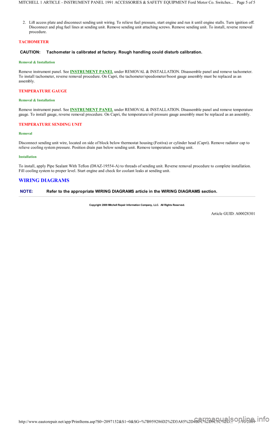
2. Lift access plate and disconnect sending unit wiring. To relieve fuel pressure, start engine and run it until engine stalls. Turn ignition off.
Disconnect and plug fuel lines at sending unit. Remove sending u n it a t t a c h in g sc r e ws. R e mo ve se n d in g u n it . To in st a l l , r e ve r se removal
procedure.
TACHOMETER
Removal & Installation
Remo ve in st ru men t p an el . See INSTRUMENT PANEL under REMOVAL & INSTALLATION. Disassemble panel and remove tachometer.
To install tachometer, reverse removal procedure. On Capri, the tachometer/speedometer/boost gauge assembly must be replaced as an
assembly.
TEMPERATURE GAUGE
Removal & Installation
Remo ve in st ru men t p an el . See INSTRUMENT PANEL under REMOVAL & INSTALLATION. Disassemble panel and remove temperature
gauge. To install gauge, reverse removal procedure. On Capri, the temperature/oil pressure gauge assembly must be replaced as an assembly.
TEMPERATURE SENDING UNIT
Removal
Disconnect sending unit wire, located on side of block below thermostat housing (Festiva) or cylinder head (Capri). Remove radiator cap to
relieve cooling system pressure. Position drain pan below sending unit. Remove temperature sending unit.
Installation
To install, apply Pipe Sealant With Teflon (D8AZ-19554-A) to threads of sending unit. Reverse removal procedure to complete installation.
Fill cooling system to proper level. Start engine and check for coolant leaks at sending unit.
WIRING DIAGRAMS
CAUT ION: T achom eter is calibrated at factory. Rough handling could disturb calibration.
NOTE:Refer to the appropriate WIRING DIAGRAMS article in the WIRING DIAGRAMS section.
Copyr ight 2009 Mitchell Repair Information Company, LLC. All Rights Reserved.
Article GUID: A00028301
Page 5 of 5 MITCHELL 1 ARTICLE - INSTRUMENT PANEL 1991 ACCESSORIES & SAFETY EQUIPMENT Ford Motor Co. Switches
...
3/10/2009 http://www.eautorepair.net/app/PrintItems.asp?S0=2097152&S1=0&SG=%7B959286D2%2D3A85%2D4BFC%2D9C5C%2D
...
Page 67 of 454
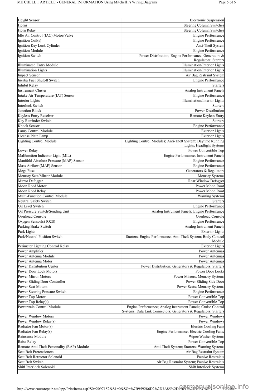
Height SensorElectronic Suspension
HornsSteering Column Switches
Horn RelaySteering Column Switches
Idle Air Control (IAC) Motor/ValveEngine Performance
Ignition Coil(s)Engine Performance
Ignition Key Lock CylinderAnti-Theft System
Ignition ModuleEngine Performance
Ignition SwitchPower Distribution; Engine Performance; Generators &
Regulators; Starters
Illuminated Entry ModuleIllumination/Interior Lights
Illumination LightsIllumination/Interior Lights
Impact SensorAir Bag Restraint System
Inertia Fuel Shutoff SwitchEngine Performance
In h ib it Rel ayStarters
Instrument ClusterAnalog Instrument Panels
Intake Air Temperature (IAT) SensorEngine Performance
Interior LightsIllumination/Interior Lights
In t erl o ck Swit chStarters
Junction BlockPower Distribution
Keyless Entry ReceiverRemote Keyless Entry
Key Reminder SwitchStarters
Knock SensorEngine Performance
Lamp Control ModuleExterior Lights
License Plate LampExterior Lights
Lighting Control ModuleLighting Control Modules; Anti-Theft System; Daytime Running
Lights; Headlight Systems
Lower RelayPower Convertible Top
Malfunction Indicator Light (MIL)Engine Performance; Instrument Panels
Manifold Absolute Pressure (MAP) SensorEngine Performance
Mass Airflow (MAF) SensorEngine Performance
Mega FuseGenerators & Regulators
Memory Seat/Mirror ModuleMemory Systems
M ir r o r De fo gge rRear Window Defogger
Moon Roof MotorPower Moon Roof
Moon Roof RelayPower Moon Roof
Multi-Function Control ModuleWarning Systems
Neutral Safety SwitchStarters
Oil Level SwitchEngine Performance
Oil Pressure Switch/Sending UnitAnalog Instrument Panels; Engine Performance
Overhead ConsoleOverhead Console
Oxygen Sensor(s) (O2S)Engine Performance
Parking Brake SwitchAnalog Instrument Panels
Park LightsExterior Lights
Park/Neutral Position SwitchStarters; Engine Performance; Anti-Theft System; Body Control
Module
Perimeter Lighting Control RelayExterior Lights
Power AmplifierPower Antennas
Power Antenna ModulePower Antennas
Power Antenna MotorPower Antennas
Power Distribution CenterPower Distribution; Generators & Regulators; Starters
Power Door Lock MotorsPower Door Locks
Power Mirror MotorsPower Mirrors; Memory Systems
Power Sliding Door ControllerPower Sliding Side Door
Power Seat MotorsPower Seats; Memory Systems
Power Steering Pressure SwitchEngine Performance
Power Top MotorPower Convertible Top
Power Top Relay(s)Power Convertible Top
Powertrain Control ModuleEngine Performance; Analog Instrument Panels; Cruise Control
Systems; Data Link Connectors; Generators & Regulators; Starters
Power Window MotorsPower Windows
Power Window Relay(s)Power Windows
Radiator Fan Motor(s)Electric Cooling Fans
Radiator Fan Relay(s)Engine Performance; Electric Cooling Fans;
Rainsense ModuleWiper/Washer Systems
Raise RelayPower Convertible Top
Remote Anti-Theft Personality (RAP) ModuleAnti-Theft System; Starters; Warning Systems
Seat Belt PretensionersAir Bag Restraint System
Seat Belt Retractor SolenoidPassive Restraints
Seat Belt SwitchAir Bag Restraint System; Passive Restraints
Shift Interlock SolenoidShift Interlock Systems
Page 5 of 6 MITCHELL 1 ARTICLE - GENERAL INFORMATION Using Mitchell1's Wiring Diagrams
3/10/2009 http://www.eautorepair.net/app/PrintItems.asp?S0=2097152&S1=0&SG=%7B959286D2%2D3A85%2D4BFC%2D9C5C%2D
...
Page 112 of 454
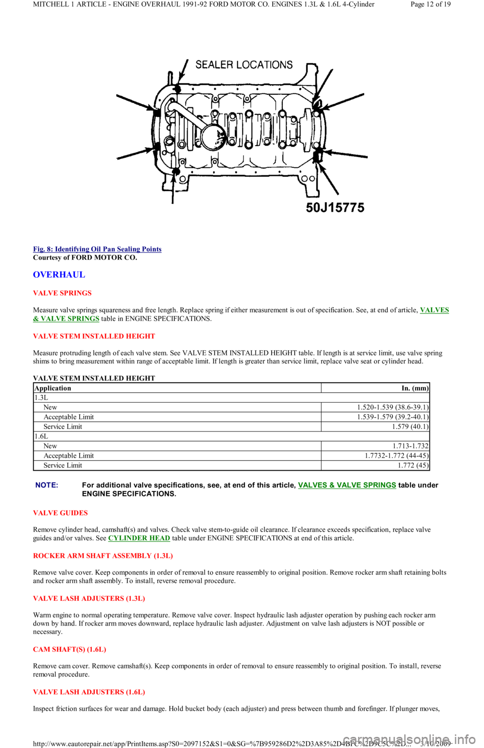
Fig. 8: Identifying Oil Pan Sealing Points
Courtesy of FORD MOTOR CO.
OVERHAUL
VALVE SPRINGS
Measure valve springs squareness and free length. Replace spring if either measurement is out of specification. See, at end of article, VALVES
& VALVE SPRINGS table in ENGINE SPECIFICATIONS.
VALVE STEM INSTALLED HEIGHT
Measure protruding length of each valve stem. See VALVE STEM INSTALLED HEIGHT table. If length is at service limit, use valve spring
shims to bring measurement within range of acceptable limit. If length is greater than service limit, replace valve seat or cylinder head.
VALVE STEM INSTALLED HEIGHT
VALVE GUIDES
Remove cylinder head, camshaft(s) and valves. Check valve stem-to-guide oil clearance. If clearance exceeds specification, replace valve
guides and/or valves. See CYLINDER HEAD
table under ENGINE SPECIFICATIONS at end of this article.
ROCKER ARM SHAFT ASSEMBLY (1.3L)
Remove valve cover. Keep components in order of removal to ensure reassembly to original position. Remove rocker arm shaft retaining bolts
and rocker arm shaft assembly. To install, reverse removal procedure.
VALVE LASH ADJUSTERS (1.3L)
Warm engine to normal operating temperature. Remove valve cover. Inspect hydraulic lash adjuster operation by pushing each rocker arm
down by hand. If rocker arm moves downward, replace hydraulic lash adjuster. Adjustment on valve lash adjusters is NOT possible or
necessary.
CAM SHAFT(S) (1.6L)
Remove cam cover. Remove camshaft(s). Keep components in order of removal to ensure reassembly to original position. To install, reverse
removal procedure.
VALVE LASH ADJUSTERS (1.6L)
Inspect friction surfaces for wear and damage. Hold bucket body (each adjuster) and press between thumb and forefinger. If plunge r mo ve s,
ApplicationIn. (mm)
1.3L
New1.520-1.539 (38.6-39.1)
Acceptable Limit1.539-1.579 (39.2-40.1)
Service Limit1.579 (40.1)
1.6L
New1.713-1.732
Acceptable Limit1.7732-1.772 (44-45)
Service Limit1.772 (45)
NOTE:For additional valve specifications, see, at end of this article, VALVES & VALVE SPRINGS
table under
ENGINE SPECIFICAT IONS.
Page 12 of 19 MITCHELL 1 ARTICLE - ENGINE OVERHAUL 1991-92 FORD MOTOR CO. ENGINES 1.3L & 1.6L 4-Cylinder
3/10/2009 http://www.eautorepair.net/app/PrintItems.asp?S0=2097152&S1=0&SG=%7B959286D2%2D3A85%2D4BFC%2D9C5C%2D
...
Page 116 of 454
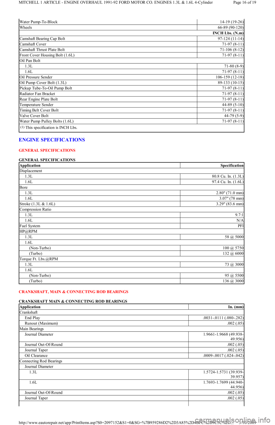
ENGINE SPECIFICATIONS
GENERAL SPECIFICATIONS
GENERAL SPECIFICATIONS
CRANKSHAFT, MAIN & CONNECTING ROD BEARINGS
CRANKSHAFT MAIN & CONNECTING ROD BEARINGS
Water Pump-To-Block14-19 (19-26)
Wheels66-89 (90-120)
INCH Lbs. (N.m)
Camshaft Bearing Cap Bolt97-124 (11-14)
Camshaft Cover71-97 (8-11)
Camshaft Thrust Plate Bolt71-106 (8-12)
Front Cover Housing Bolt (1.6L)71-97 (8-11)
Oil Pan Bolt
1.3L71-80 (8-9)
1.6L71-97 (8-11)
Oil Pressure Sender106-159 (12-18)
Oil Pump Cover Bolt (1.3L)89-133 (10-15)
Pickup Tube-To-Oil Pump Bolt71-97 (8-11)
Radiator Fan Bracket71-97 (8-11)
Rear Engine Plate Bolt71-97 (8-11)
Temperature Sender44-89 (5-10)
Timing Belt Cover Bolt71-97 (8-11)
Valve Cover Bolt44-79 (5-9)
Water Pump Pulley Bolts (1.6L)71-97 (8-11)
(1)This specification is INCH Lbs.
ApplicationSpecification
Displacement
1.3L80.8 Cu. In. (1.3L)
1.6L97.4 Cu. In. (1.6L)
Bore
1.3L2.80" (71.0 mm)
1.6L3.07" (78 mm)
Stroke (1.3L & 1.6L)3.29" (83.6 mm)
Compression Ratio
1.3L9.7:1
1.6LN/A
Fuel SystemPFI
HP@RPM
1.3L58 @ 5000
1.6L
(Non-Turbo)100 @ 5750
(Turbo)132 @ 6000
Torque Ft. Lbs.@RPM
1.3L73 @ 3000
1.6L
(Non-Turbo)95 @ 5500
(Turbo)136 @ 3000
ApplicationIn. (mm)
Crankshaft
End Play.0031-.0111 (.080-.282)
Runout (Maximum).002 (.05)
Main Bearings
Journal Diameter1.9661-1.9668 (49.938-
49.956)
Journal Out-Of-Round.002 (.05)
Journal Taper.002 (.05)
Oil Clearance.0009-.0017 (.024-.042)
Connecting Rod Bearings
Journal Diameter
1.3L1.5724-1.5731 (39.939-
39.957)
1.6L1.7693-1.7699 (44.940-
44.956)
Journal Out-Of-Round.002 (.05)
Journal Taper.002 (.05)
Page 16 of 19 MITCHELL 1 ARTICLE - ENGINE OVERHAUL 1991-92 FORD MOTOR CO. ENGINES 1.3L & 1.6L 4-Cylinder
3/10/2009 http://www.eautorepair.net/app/PrintItems.asp?S0=2097152&S1=0&SG=%7B959286D2%2D3A85%2D4BFC%2D9C5C%2D
...
Page 153 of 454
Back To Article
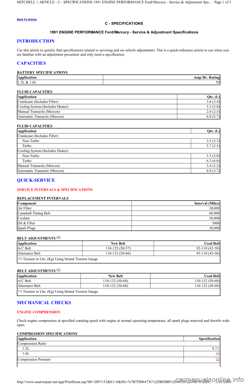
C - SPECIFICATIONS
1991 ENGINE PERFORMANCE Ford/Mercury - Service & Adjustm ent Specifications
INTRODUCTION
Use this article to quickly find specifications related to servicing and on-vehicle adjustments. This is a quick-reference article to use when you
are familiar with an adjustment procedure and only need a specification.
CAPACITIES
BATTERY SPECIFICATIONS
FLUID CAPACITIES
FLUID CAPACITIES
QUICK-SERVICE
SERVICE INTERVALS & SPECIFICATIONS
REPLACEMENT INTERVALS
BELT ADJUSTMENTS
(1)
BELT ADJUSTMENTS
(1)
MECHANICAL CHECKS
ENGINE COMPRESSION
Check engine compression at specified cranking speed with engine at normal operating temperature, all spark plugs removed and throttle wide
open.
COMPRESSION SPECIFICATIONS
ApplicationAmp Hr. Rating
1.3L & 1.6L50
ApplicationQts. (L)
Crankcase (Includes Filter)3.6 (3.4)
Cooling System (Includes Heater)5.3 (5.0)
Manual Transaxle (Mercon)2.6 (2.5)
Automatic Transaxle (Mercon)6.0 (5.7)
ApplicationQts. (L)
Crankcase (Includes Filter)
Non-Turbo3.5 (3.3)
Turbo3.7 (3.5)
Cooling System (Includes Heater)
Non-Turbo5.3 (5.0)
Turbo6.3 (6.0)
Manual Transaxle (Mercon)3.4 (3.2)
Automatic Transaxle (Mercon)6.0 (5.7)
ComponentInterval (Miles)
Air Filter30,000
Camsh aft Timin g Bel t60,000
Coolant30,000
Oil & Filter3000
Spark Plugs30,000
ApplicationNew BeltUsed Belt
A/C Belt110-125 (50-57)92-110 (42-50)
Alternator Belt110-132 (50-60)95-110 (43-50)
(1)Tension in Lbs. (Kg) Using Strand Tension Gauge
ApplicationNew BeltUsed Belt
A/C Belt110-132 (50-60)110-132 (50-60)
Alternator Belt110-132 (50-60)110-132 (50-60)
(1)Tension in Lbs. (Kg) Using Strand Tension Gauge.
ApplicationSpecification
Compression Ratio
1.3L9.7:1
1.6L(1)
Compression Pressure(2)
Page 1 of 3 MITCHELL 1 ARTICLE - C - SPECIFICATIONS 1991 ENGINE PERFORMANCE Ford/Mercury - Service & Adjustment Spe
...
3/10/2009 http://www.eautorepair.net/app/PrintItems.asp?S0=2097152&S1=0&SG=%7B7DD6473C%2DB5BB%2D4F20%2D9D70%2D
...
Page 166 of 454
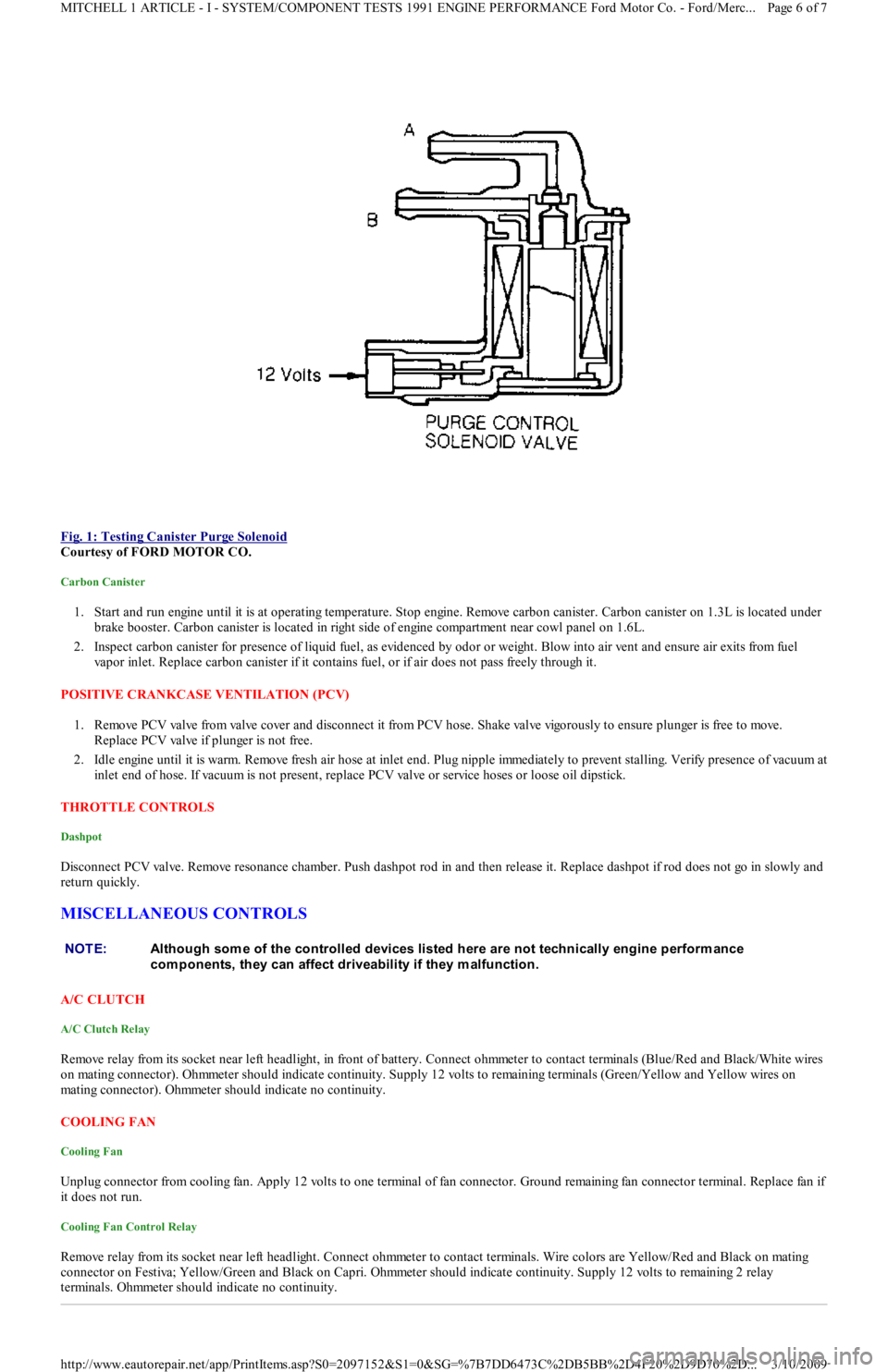
Fig. 1: Testing Canister Purge Solenoid
Courtesy of FORD MOTOR CO.
Carbon Canister
1. Start and run engine until it is at operating temperature. Stop engine. Remove carbon canister. Carbon canister on 1.3L is located under
brake booster. Carbon canister is located in right side of engine compartment near cowl panel on 1.6L.
2. Inspect carbon canister for presence of liquid fuel, as evidenced by odor or weight. Blow into air vent and ensure air exits fro m fu el
vapor inlet. Replace carbon canister if it contains fuel, or if air does not pass freely through it.
POSITIVE CRANKCASE VENTILATION (PCV)
1. Remove PCV valve from valve cover and disconnect it from PCV h o se . S h a ke va l ve vigo r o u sl y t o e n su r e p l u n ge r is fr e e t o mo ve .
Replace PCV valve if plunger is not free.
2. Idle engine until it is warm. Remove fresh air hose at inlet end. Plug nipple immediately to prevent stalling. Verify presence of vacuum at
inlet end of hose. If vacuum is not present, replace PCV valve or service hoses or loose oil dipstick.
THROTTLE CONTROLS
Dashpot
Disconnect PCV valve. Remove resonance chamber. Push dashpot rod in and then release it. Replace dashpot if rod does not go in slowly and
return quickly.
MISCELLANEOUS CONTROLS
A/C CLUTCH
A/C Clutch Relay
Remove relay from its socket near left headlight, in front of battery. Connect ohmmeter to contact terminals (Blue/Red and Black/White wires
on mating connector). Ohmmeter should indicate continuity. Supply 12 volts to remaining terminals (Green/Yellow and Yellow wires on
mating connector). Ohmmeter should indicate no continuity.
COOLING FAN
Cooling Fan
Unplug connector from cooling fan. Apply 12 volts to one terminal of fan connector. Ground remaining fan connector terminal. Replace fan if
it does not run.
Cooling Fan Control Relay
Remove relay from its socket near left headlight. Connect ohmmeter to contact terminals. Wire colors are Yellow/Red and Black on mating
connector on Festiva; Yellow/Green and Black on Capri. Ohmmeter should indicate continuity. Supply 12 volts to remaining 2 relay
terminals. Ohmmeter should indicate no continuity.
NOTE:Although som e of the controlled devices listed here are not technically engine perform ance
com ponents, they can affect driveability if they m alfunction.
Page 6 of 7 MITCHELL 1 ARTICLE - I - SYSTEM/COMPONENT TESTS 1991 ENGINE PERFORMANCE Ford Motor Co. - Ford/Merc
...
3/10/2009 http://www.eautorepair.net/app/PrintItems.asp?S0=2097152&S1=0&SG=%7B7DD6473C%2DB5BB%2D4F20%2D9D70%2D
...
Page 177 of 454
connector while moving vane in VAF meter. Voltage should be as specified in VAF METER VOLTAGE table. If voltage is okay,
repair VAF wire to ECA. If voltage is not okay, go to next step.
VAF METER VOLTAGE
4. Unplug connector from VAF. Using jumper wires, connect VPWR and SIGRTN terminals on VAF connector to corresponding terminals
on VAF meter. Leave VAF and VMREF wires disconnected. Measure voltage between VAF terminal at VAF meter, and SIGRTN pin at
harness connector while moving vane in VAF meter. Voltage should be as specified in VAF METER VOLTAGE
table. If voltage is
okay, repair VMREF wire to ECA. If voltage is not okay, go to next step.
5. Unplug connector from VAF meter. Turn ignition on. Measure voltage between SIGRTN and VPWR wire. If voltage is more than 10
volts, replace VAF meter. If voltage is not more than 10 volts, go to next step.
6. Unplug VAF meter connector. Turn ignition on. Measure voltage between VAF meter VPWR wire and ground. If voltage is more than
10 volts, repair VAF wire to ECA. If voltage is not more than 10 volts, go to PINPOINT TEST VPWR.
PINPOINT TEST ECT - ENGINE COOLANT TEMPERATURE SENSOR
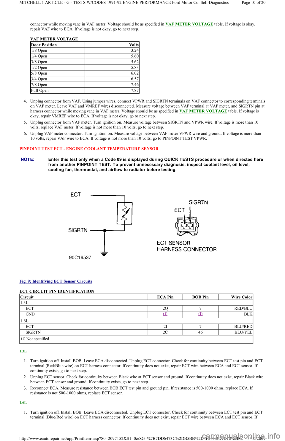
Fig. 9: Identifying ECT Sensor Circuits
ECT CIRCUIT PIN IDENTIFICATION
1.3L
1. Turn ignition off. Install BOB. Leave ECA disconnected. Unplug ECT connector. Check for continuity between ECT test pin and ECT
terminal (Red/Blue wire) on ECT harness connector. If continuity does not exist, repair ECT wire between ECA and ECT sensor. If
continuity exists, go to next step.
2. Unplug ECT sensor. Check for continuity between Black wire at ECT sensor and ground. If continuity does not exist, repair Black wire
between ECT sensor and ground. If continuity exists, go to next step.
3. Reconnect ECA. Measure resistance between BOB ECT test pin and ground pin. If resistance is 500-1000 ohms, replace ECA. If
resistance is not 500-1000 ohms, replace ECT sensor.
1.6L
1. Turn ignition off. Install BOB. Leave ECA disconnected. Unplug ECT connector. Check for continuity between ECT test pin and ECT
terminal (Blue/Red wire) on ECT harness connector. If continuity does not exist, repair ECT wire between ECA and ECT sensor. If
Door PositionVolts
1/8 Open3.24
1/4 Open5.60
3/8 Open5.62
1/2 Open5.83
5/8 Open6.02
3/4 Open6.57
7/8 Open7.46
Full Open7.87
NOTE:Enter this test only when a Code 09 is displayed during QUICK T EST S procedure or when directed here
from another PINPOINT T EST . T o prevent unnecessary diagnosis, inspect coolant level, oil level,
cooling fan, therm ostat, and airflow to radiator before testing.
CircuitECA PinBOB PinWire Color
1.3L
ECT2Q7RED/BLU
GND(1) (1) BLK
1.6L
ECT2I7BLU/RED
SIGRTN2C46BLU/YEL
(1)Not specified.
Page 10 of 20 MITCHELL 1 ARTICLE - G - TESTS W/CODES 1991-92 ENGINE PERFORMANCE Ford Motor Co. Self-Diagnostics
3/10/2009 http://www.eautorepair.net/app/PrintItems.asp?S0=2097152&S1=0&SG=%7B7DD6473C%2DB5BB%2D4F20%2D9D70%2D
...