strut FORD FESTIVA 1991 Service Manual
[x] Cancel search | Manufacturer: FORD, Model Year: 1991, Model line: FESTIVA, Model: FORD FESTIVA 1991Pages: 454, PDF Size: 9.53 MB
Page 32 of 454
lock nut. Discard axle lock nut. Separate tie rod end from knuckle.
2. Disconnect brake hose from strut (if necessary). Remove brake caliper assembly from knuckle and wire out of way. Remove nuts and
bolts holding ball joint and strut to knuckle assembly.
3. Remove knuckle assembly from ball joint and drive shaft. If binding occurs, use a dual-jawed puller to force knuckle/hub/rotor assembly
off drive axle shaft.
4. Using a puller, separate knuckle from wheel hub. Retain original outer bearing preload spacer to maintain bearing preload setting. If
replacing bearing, change spacer to maintain proper bearing preload (if necessary). See FRONT WHEEL BEARINGS under REMOVAL
& INSTALLATION. Scribe match marks between hub and rotor assembly. Remove rotor-to-hub bolts. Separate hub from rotor.
Installation
Align marks and install rotor on hub. Press knuckle and preload spacer into wheel hub assembly. To complete installation, reverse removal
procedure. Tighten axle shaft lock nut to 117-175 ft. lbs. (159-237 N.m).
REAR BRAKE CALIPER & PADS
Removal (Capri)
1. Raise and support vehicle. Remove tire and wheel assembly. Using needle-nose pliers, remove parking brake return spring. Loosen
parking brake cable housing adjusting nut. Remove cable housing from bracket on lower control arm. Loosen parking brake cable
bracket-to-caliper attaching bolt. Remove parking brake cable from caliper.
2. Remove lower caliper retaining bolt. Pivot caliper upward on upper caliper guide pin. Remove brake pad retaining spring, pads and
shims. If replacing rear brake pads only, reverse removal procedure to install. If removing caliper, proceed to next step.
3. Remove attaching clip from brake flex hose. Remove flex hose banjo bolt from caliper and discard copper washers. Remove lower
caliper retaining bolt. Using a cold chisel, remove upper caliper guide pin dust cap. Using an Allen wrench, remove upper caliper guide
pin. Lift caliper off rotor.
Installation
1. To install, fit brake pads and shims into caliper anchor plate. Remove upper guide pin and lower guide pin bushing from caliper.
Remove guide pin and guide pin bushing dust boots. Lubricate upper guide pin and lower guide pin bushing with Disc Brake Caliper
Slide Grease (D7AZ-19590-A).
2. To complete installation, reverse removal procedure. To fit caliper over new brake pads, it may be necessary to rotate caliper piston into
caliper bore. Use NEW copper washers on flex hose. Bleed brakes, and then pump brake pedal several times to seat pads.
REAR BRAKE ROTOR
Removal & Installation (Capri)
See REAR WHEEL BEARINGS under REMOVAL & INSTALLATION.
REAR BRAKE SHOES
Removal & Installation (Festiva)
Remove brake drum. Remove hold-down springs. Remove return springs. Remove self adjuster. See Fig. 8 . To install, reverse removal
procedure. Apply brake grease to all shoe contact points. See REAR BRAKE SHOES under ADJUSTMENTS.
REAR WHEEL CYLINDER
Removal & Installation (Festiva)
Remove rear brake shoes. Disconnect brake line from wheel cylinder. Remove wheel cylinder. To install, reverse removal procedure. Bleed
brake system.
MASTER BRAKE CYLINDER
Removal
Disconnect low fluid level sensor wiring (if equipped). Drain some brake fluid from reservoir. Disconnect brake lines from master cylinder.
Cap lines and master cylinder ports. Remove attaching nuts and master cylinder.
Installation
To install, reverse removal procedure. Fill master cylinder to proper level and bleed hydraulic system (if necessary).
POWER BRAKE UNIT
Removal & Installation
Remove master cylinder. Disconnect vacuum line. Remove clevis pin at brake pedal. Remove power brake unit. To install, reverse removal
procedure.
FRONT WHEEL BEARINGS NOTE:Hub and rotor are a m atched and balanced assem bly. Before rem oving rotor, locate paint or etch
m ark indicating proper hub-to-rotor alignm ent. If m arks are not present, m ark hub and rotor for
assem bly alignm ent. Failure to properly align hub and rotor can result in an im balance condition.
Page 5 of 12 MITCHELL 1 ARTICLE - BRAKE SYSTEM 1991-92 BRAKES Disc & Drum
3/10/2009 http://www.eautorepair.net/app/PrintItems.asp?S0=2097152&S1=0&SG=%7B7DD6473C%2DB5BB%2D4F20%2D9D70%2D
...
Page 38 of 454
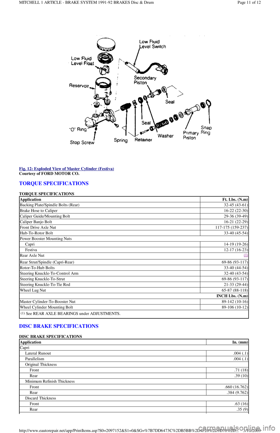
Fig. 12: Exploded View of Master Cylinder (Festiva)
Courtesy of FORD MOTOR CO.
TORQUE SPECIFICATIONS
TORQUE SPECIFICATIONS
DISC BRAKE SPECIFICATIONS
DISC BRAKE SPECIFICATIONS
ApplicationFt. Lbs. (N.m)
Backing Plate/Spindle Bolts (Rear)32-45 (43-61)
Brake Hose to Caliper16-22 (22-30)
Caliper Guide/Mounting Bolt29-36 (39-49)
Caliper Banjo Bolt16-21 (22-29)
Front Drive Axle Nut117-175 (159-237)
Hub-To-Rotor Bolt33-40 (45-54)
Power Booster Mounting Nuts
Capri14-19 (19-26)
Festiva12-17 (16-23)
Rear Axle Nut(1)
Rear Strut/Spindle (Capri-Rear)69-86 (93-117)
Rotor-To-Hub Bolts33-40 (44-54)
Steering Knuckle-To-Control Arm32-40 (43-54)
Steering Knuckle-To-Strut69-86 (93-117)
Steering Knuckle-To-Tie Rod21-33 (29-44)
Wheel Lug Nut65-87 (88-118)
INCH Lbs. (N.m)
Master Cylinder-To-Booster Nut89-142 (10-16)
Wheel Cylinder Mounting Bolt89-106 (10-12)
(1)See REAR AXLE BEARINGS under ADJUSTMENTS.
ApplicationIn. (mm)
Capri
Lateral Runout.004 (.1)
Parallelism.004 (.1)
Original Thickness
Front.71 (18)
Rear.39 (10)
Min imu m Refin ish Th ickn ess
Front.660 (16.762)
Rear.384 (9.762)
Discard Thickness
Front.63 (16)
Rear.35 (9)
Page 11 of 12 MITCHELL 1 ARTICLE - BRAKE SYSTEM 1991-92 BRAKES Disc & Drum
3/10/2009 http://www.eautorepair.net/app/PrintItems.asp?S0=2097152&S1=0&SG=%7B7DD6473C%2DB5BB%2D4F20%2D9D70%2D
...
Page 42 of 454
Installation (All)
1. To install axle shaft, reverse removal procedure. Always install a NEW retaining circlip. Check seals at both ends of axle shaft. If
necessary, replace seals prior to installation. Lubricate transaxle seal lip with transaxle oil. See Fig. 1
.
2. After installing axle shaft into transaxle, pull axle shaft outward by hand to ensure proper engagement of retaining circlip and snap ring.
Install axle shaft into wheel hub. Align suspension alignment marks and tighten nuts.
INTERMEDIATE SHAFT
Removal
Intermediate shaft and axle shaft are removed as an assembly. See FWD AXLE SHAFTS under REMOVAL, DISASSEMBLY,
REASSEMBLY & INSTALLATION.
Disassembly
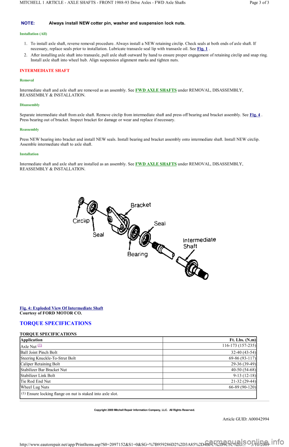
Separate intermediate shaft from axle shaft. Remove circlip from intermediate shaft and press off bearing and bracket assembly. See Fig. 4 .
Press bearing out of bracket. Inspect bracket for damage or wear and replace if necessary.
Reassembly
Press NEW bearing into bracket and install NEW seals. Install bearing and bracket assembly onto intermediate shaft. Install NEW circlip.
Assemble intermediate shaft to axle shaft.
Installation
Intermediate shaft and axle shaft are installed as an assembly. See FWD AXLE SHAFTS under REMOVAL, DISASSEMBLY,
REASSEMBLY & INSTALLATION.
Fig. 4: Exploded View Of Intermediate Shaft
Courtesy of FORD MOTOR CO.
TORQUE SPECIFICATIONS
TORQUE SPECIFICATIONS NOTE:Always install NEW cotter pin, washer and suspension lock nuts.
ApplicationFt. Lbs. (N.m)
Axle Nut (1) 116-173 (157-235)
Ball Joint Pinch Bolt32-40 (43-54)
Steering Knuckle-To-Strut Bolt69-86 (93-117)
Caliper Retaining Bolt29-36 (39-49)
Stabilizer Bar Bracket Nut40-50 (54-68)
Stabilizer Link Bolt9-13 (12-18)
Tie Rod End Nut21-32 (29-44)
Wheel Lug Nuts66-89 (90-120)
(1)Ensure locking flange on nut is staked into axle slot.
Copyr ight 2009 Mitchell Repair Information Company, LLC. All Rights Reserved.
Article GUID: A00042994
Page 3 of 3 MITCHELL 1 ARTICLE - AXLE SHAFTS - FRONT 1988-93 Drive Axles - FWD Axle Shafts
3/10/2009 http://www.eautorepair.net/app/PrintItems.asp?S0=2097152&S1=0&SG=%7B959286D2%2D3A85%2D4BFC%2D9C5C%2D
...
Page 46 of 454
Back To Article
ELECT RICAL COMPONENT LOCAT OR
1991-92 ELECT RICAL COMPONENT LOCAT ION Ford Motor Co. Electrical Com ponents
BUZZERS, RELAYS & TIMERS
BUZZERS, RELAYS & TIMERS LOCATION
CIRCUIT PROTECTION DEVICES
CIRCUIT PROTECTION DEVICES LOCATION
CONTROL UNITS
CONTROL UNITS LOCATION
SENDING UNITS & SENSORS
SENDING UNITS & SENSORS LOCATION
MOTORS
MOTORS LOCATION
ComponentLocation
A/C Clutch Relay (1991)On right front of engine bay, near power
steering pump.
A/C RelayOn left front corner of engine bay, left of
cooling fan. See Fig. 1
& Fig. 2
A/C Wide Open Throttle (WAC) RelayOn left front corner of engine bay, left of
cooling fan. See Fig. 1
& Fig. 2 .
Cooling Fan RelayOn left front fender panel, near
headlight. See Fig. 1
& Fig. 2 .
Condenser Fan RelayOn left front of engine bay, left of
cooling fan. See Fig. 1
& Fig. 2 .
Daytime Running Light (DRL) Relay (Canada) (1992)On left front corner of engine bay, near
headlight. See Fig. 1
.
Fuel Pump RelayBehind left side of dash, near ECA.
Headlight RelayBehind left headlight. See Fig. 1 .
Horn RelayUnder left side of dash. See Fig. 3 .
Main RelayIn left front corner of engine bay, near
battery.
P a r kin g Ligh t R e l a yOn right front corner of engine bay. See
Fig. 1
.
Turn Signal/Flasher RelayUnder left side of dash, behind ECA.
See Fig. 3
.
ComponentLocation
A/C In-Line FuseOn left side of heater case.
Condenser Fan In-Line FuseOn right side of steering column.
Fuse PanelBehind access panel, to left of steering column.
Fusible LinksOn left front strut tower. See Fig. 1 .
ComponentLocation
Electronic Control Assembly (ECA)Behind left side of dash, left of steering column.
Passive Restraint ModuleUnder driver's seat.
ComponentLocation
Airflow MeterOn right front corner of engine bay. See Fig. 1 .
Coolant Temperature Sending UnitBelow thermostat housing.
Crankshaft Position SensorInside distributor. See Fig. 1 .
EGR Temperature Sensor (1991)In exhaust manifold, near EGR valve.
Engine Coolant Temperature (ECT) SensorOn top of engine, near injector No. 1.
Fuel Gauge Sending Unit (1992)In fu el t an k.
Throttle Position Sensor (TPS)On left side of throttle body. See Fig. 1 .
ComponentLocation
Blower MotorUnder center of dash, behind
radio.
Windshield Washer Motors:
Front (1991)On right front fender panel,
bottom of washer reservoir.
Front (1992)On left front corner of engine
bay, in front of battery.
RearOn body panel, behind right
rear quarter panel.
Windshield Wiper Motor
Page 1 of 3 MITCHELL 1 ARTICLE - ELECTRICAL COMPONENT LOCATOR 1991-92 ELECTRICAL COMPONENT LOCATION For...
3/10/2009 http://www.eautorepair.net/app/PrintItems.asp?S0=2097152&S1=0&SG=%7B959286D2%2D3A85%2D4BFC%2D9C5C%2D
...
Page 47 of 454
SOLENOIDS & SOLENOID VALVES
SOLENOIDS & SOLENOID VALVES LOCATION
SWITCHES
SWITCHES LOCATION
MISCELLANEOUS
MISCELLANEOUS LOCATION
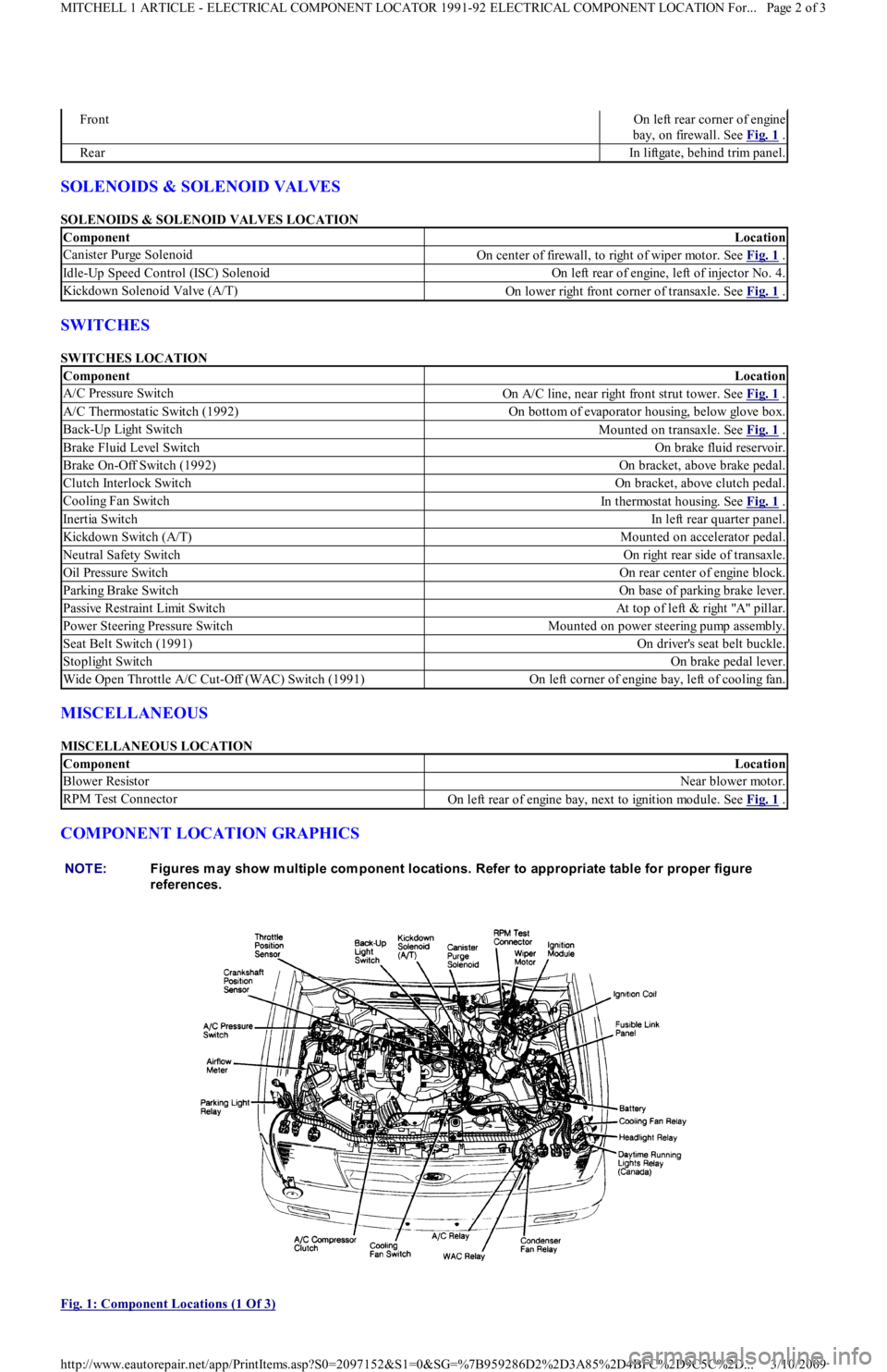
COMPONENT LOCATION GRAPHICS
Fig. 1: Component Locations (1 Of 3)
FrontOn left rear corner of engine
bay, on firewall. See Fig. 1
.
RearIn liftgate, behind trim panel.
ComponentLocation
Canister Purge SolenoidOn center of firewall, to right of wiper motor. See Fig. 1 .
Idle-Up Speed Control (ISC) SolenoidOn left rear of engine, left of injector No. 4.
Kickdown Solenoid Valve (A/T)On lower right front corner of transaxle. See Fig. 1 .
ComponentLocation
A/C Pressure SwitchOn A/C line, near right front strut tower. See Fig. 1 .
A/C Thermostatic Switch (1992)On bottom of evaporator housing, below glove box.
Back-Up Light SwitchMounted on transaxle. See Fig. 1 .
Brake Fluid Level SwitchOn brake fluid reservoir.
Brake On-Off Switch (1992)On bracket, above brake pedal.
Clutch Interlock SwitchOn bracket, above clutch pedal.
Cooling Fan SwitchIn thermostat housing. See Fig. 1 .
Inertia SwitchIn left rear quarter panel.
Kickdown Switch (A/T)Mounted on accelerator pedal.
Neutral Safety SwitchOn right rear side of transaxle.
Oil Pressure SwitchOn rear center of engine block.
Parking Brake SwitchOn base of parking brake lever.
Passive Restraint Limit SwitchAt top of left & right "A" pillar.
Power Steering Pressure SwitchMounted on power steering pump assembly.
Seat Belt Switch (1991)On driver's seat belt buckle.
Stoplight SwitchOn brake pedal lever.
Wide Open Throttle A/C Cut-Off (WAC) Switch (1991)On left corner of engine bay, left of cooling fan.
ComponentLocation
Blower ResistorNear blower motor.
RPM Test ConnectorOn left rear of engine bay, next to ignition module. See Fig. 1 .
NOTE:Figures m ay show m ultiple com ponent locations. Refer to appropriate table for proper figure
references.
Page 2 of 3 MITCHELL 1 ARTICLE - ELECTRICAL COMPONENT LOCATOR 1991-92 ELECTRICAL COMPONENT LOCATION For...
3/10/2009 http://www.eautorepair.net/app/PrintItems.asp?S0=2097152&S1=0&SG=%7B959286D2%2D3A85%2D4BFC%2D9C5C%2D
...
Page 156 of 454
Back To Article
F - BASIC TESTING
1991-92 ENGINE PERFORMANCE Ford Motor Co. Basic Diagnostic Procedures
INTRODUCTION
The following diagnostic steps help prevent overlooking simple problems and begin diagnosis for a no-start condition.
The first step in diagnosing any driveability problem is to verify the complaint. Test drive the vehicle under the conditions in which the
problem reportedly occurred.
Before entering self-diagnostics, perform a careful and complete visual inspection. Most engine control problems result from mechanical
breakdowns, poor electrical connections or damaged/misrouted vacuum hoses. Before condemning the computerized system, perform each test
listed in this article.
PRELIMINARY INSPECTION & ADJUSTMENTS
VISUAL INSPECTION
Perform a visual inspection of all electrical wiring. Look for chafed, stretched, cut or pinched wiring. Ensure electrical connections fit tightly
and are not corroded. Ensure vacuum hoses are properly routed and are not cut or pinched. If necessary, see VACUUM DIAGRAMS article in
the ENGINE PERFORMANCE Section to verify routing and connections. Inspect air induction system for possible vacuum leaks.
MECHANICAL INSPECTION
Compression
Engine mechanical condition can be checked using a compression gauge, vacuum gauge or engine analyzer. See engine analyzer instruction
manual for specific instructions. Lowest compression reading must be not less than 75 percent of highest reading.
Exhaust System Backpressure
Exhaust system can be checked with a vacuum gauge or a 0-5 psi pressure gauge. If a pressure gauge is used, remove O2 sensor. Connect gauge
to O2 sensor port. Start engine, and run at 2500 RPM. If exhaust system backpressure is more than 2 psi, exhaust system or catalytic converter
is plugged.
If a vacuum gauge is used, connect it to intake manifold vacuum. Start engine. Observe vacuum gauge. Open throttle part way and hold steady.
If vacuum gauge drops slowly after stabilizing, check exhaust system for a restriction.
FUEL PRESSURE
Fuel Pressure Release
Start engine (if possible), and unplug VAF meter connector. When engine stalls, turn ignition off and reconnect VAF meter wiring. Usin g sh o p
towel, cover fitting to absorb leakage when opening fuel system.
Fuel Pressure Check
1. Connect fuel pressure gauge between fuel filter and fuel rail. Open main valve, and close drain valve. Locate fuel pump check connector
in engine compartment, near left strut. Connect jumper wire between fuel pump test terminals (Black and Green/White wires on Capri
or Black and Green/Red wires on Festiva).
2. Turn ignition on to activate fuel pump. If pump does not run, check fuel pump circuit. If possible, start engine. Measure and record fuel
pressure. For fuel pressure specifications, see FUEL PRESSURE SPECIFICATIONS
article. Disconnect vacuum from pressure
regulator. Turn engine off. Wait 5 minutes and ensure residual pressure is at least 21 psi (1.5 kg/cm
2 ).
3. Operate fuel pump by reconnecting jumper wire at fuel pump check connector. Check fuel pump performance. Pinch hose between
pressure gauge and fuel filter. Do not hold longer than necessary to check pressure.For fuel pressure specifications, see FUEL
PRESSURE SPECIFICATIONS article. If pump does not meet specifications, check fuel pump circuit, fuel pump, fuel tank and fuel
filter or replace fuel pump.
FUEL PUMP PERFORMANCE NOTE:Unless stated otherwise in test procedure, perform all voltage tests with a Digital Volt-Ohm m eter
(DVOM) with a m inim um 10-m egohm input im pedance.
CAUT ION: DO NOT use ignition switch during com pression tests on fuel injected vehicles. Fuel injectors are
triggered by ignition switch during cranking m ode. Use a rem ote starter to crank engine to prevent fire
hazard and catalytic converter and engine oiling system contam ination.
WARNING:ALWAYS relieve fuel pressure before disconnecting any fuel injection system com ponent. DO NOT
allow fuel to contact engine or electrical com ponents.
NOTE:For 1991 fuel pressure specifications, see FUEL PRESSURE SPECIFICAT IONS
article. For 1992 fuel
pressure specifications, see FUEL PRESSURE SPECIFICAT IONS
article.
ApplicationPressure psi (kg/cm2 )Min. Vol. in 10 sec. Ozs. (cc)
Capri(1) 5.5 (167)
Festiva(1) 7.4 (220)
Page 1 of 4 MITCHELL 1 ARTICLE - F - BASIC TESTING 1991-92 ENGINE PERFORMANCE Ford Motor Co. Basic Diagnostic Proced
...
3/10/2009 http://www.eautorepair.net/app/PrintItems.asp?S0=2097152&S1=0&SG=%7B959286D2%2D3A85%2D4BFC%2D9C5C%2D
...
Page 243 of 454
POWER STEERING TROUBLE SHOOTING
BASIC POWER STEERING TROUBLE SHOOTING CHART
Steering gear adjustment too looseSee MANUAL STEERING
GEAR article
Steering arms loose on knucklesTighten and check steering
linkage
Rack and pinion mounting looseTighten all mounting bolts
Rack and pinion out of adjustmentSee adjustment in STEERING
article
Tie rod end looseTighten and check steering
linkage
Excessive Pitman shaft-to-ball nut lashRepair as necessary
Poor Returnability
Lack of lubricant in ball joint or linkageLubricate and service systems
Binding in linkage or ball jointsSee STEERING LINKAGE
and SUSPENSION article
Improper front end alignmentSee WHEEL ALIGNMENT
article
Improper tire pressureInflate to proper pressure
Tie rod bindingInflate to proper pressure
Shaft seal rubbing shaftSee STEERING COLUMN
article
Excessive Vertical Motion
Improper tire pressureInflate to proper pressure
Tires, wheels or rotors out of balanceBalance tires then check
wheels and rotors
Worn or faulty shock absorbersCheck and replace if necessary
Loose tie rod ends or steeringTighten or replace if necessary
Loose or worn wheel bearingsSee SUSPENSION article
Steering Pulls to One Side
Improper tire pressureInflate to proper pressure
Front tires are different sizesRotate or replace if necessary
Wheel bearings not adjusted properlySee FRONT SUSPENSION
article
Bent or broken suspension componentsSee FRONT SUSPENSION
article
Improper wheel alignmentSee WHEEL ALIGNMENT
article
Brakes draggingSee BRAKES article
Instability
Low or uneven tire pressureInflate to proper pressure
Loose or worn wheel bearingsSee FRONT SUSPENSION
article
Loose or worn idler arm bushingSee FRONT SUSPENSION
article
Loose or worn strut bushingsSee FRONT SUSPENSION
article
Incorrect front wheel alignmentSee WHEEL ALIGNMENT
article
Steering gear not centeredSee MANUAL STEERING
GEARS article
Springs or shockCheck and replace if necessary
Improper cross shaftSee MANUAL STEERING
GEARS article
NOTE:This is GENERAL inform ation. This article is not intended to be specific to any unique situation or
individual vehicle configuration. T he purpose of this T rouble Shooting inform ation is to provide a list
of com m on causes to problem sym ptom s. For m odel-specific T rouble Shooting, refer to SUBJECT ,
DIAGNOST IC, or T EST ING articles available in the section(s) you are accessing.
CONDITION & POSSIBLE CAUSECORRECTION
Rattle or Chucking Noise
Pressure hoses touching engine partsAdjust to proper clearance
Loose Pitman shaftAdjust or replace if necessary
Tie rods ends or Pitman arm looseTighten and check system
Rack and pinion mounts looseTighten all mounting bolts
Free play in worm gearSee POWER STEERING
GEAR article
Loose sector shaft or thrust bearing adjustmentSee POWER STEERING
GEAR
Free play in pot couplingSee STEERING COLUMN
article
Page 30 of 36 MITCHELL 1 ARTICLE - GENERAL INFORMATION Trouble Shooting - Basic Procedures
3/10/2009 http://www.eautorepair.net/app/PrintItems.asp?S0=2097152&S1=0&SG=%7B9B990D68%2D660A%2D45E9%2D8F46%2DE
...
Page 247 of 454
SUSPENSION TROUBLE SHOOTING
BASIC SUSPENSION TROUBLE SHOOTING CHART
article
Shroud or housing looseTighten holding screws
Lock plate retaining ring not seatedSee STEERING COLUMN
article
Loose sight shieldTighten holding screws
High Steering Shaft Effort
Co l u mn assemb l y misal ign edSee STEERING COLUMN
article
Improperly installed dust shieldAdjust or replace
Tight steering universal jointSee STEERING COLUMN
article
High Shift Effort
Column is out of alignmentSee STEERING COLUMN
article
Improperly installed dust shieldAdjust or replace
Seals or bearings not lubricatedSee STEERING COLUMNS
article
Mounting bracket screws too longReplace with new shorter
screws
Burrs on shift tubeRemove burrs or replace tube
Lower bowl bearing assembled wrongSee STEERING COLUMN
article
Shift tube bent or brokenReplace as necessary
Improper adjustment of shift leversSee STEERING COLUMN
article
Improper Trans. Shifting
Sheared shift tube jointReplace as necessary
Sheared lower shaft leverReplace as necessary
Improper shift lever adjustmentSee STEERING COLUMN
article
Improper gate plate adjustmentSee STEERING COLUMN
article
Excess Play in Column
Instrument panel bracket bolts looseTighten bolts and check
bracket
Broken weld nut on jacketSee STEERING COLUMN
article
Instrument bracket capsule shearedSee STEERING COLUMN
article
Column bracket/jacket bolts looseTighten bolts and check
bracket
Steering Locks in Gear
Release lever mechanismSee STEERING COLUMN
article
NOTE:This is GENERAL inform ation. This article is not intended to be specific to any unique situation or
individual vehicle configuration. T he purpose of this T rouble Shooting inform ation is to provide a list
of com m on causes to problem sym ptom s. For m odel-specific T rouble Shooting, refer to SUBJECT ,
DIAGNOST IC, or T EST ING articles available in the section(s) you are accessing.
CONDITION & POSSIBLE CAUSECORRECTION
Front End Noise
Loose or worn wheelSee Wheel Bearing
Adjustment in SUSPENSION
Worn shocks or shock mountingsReplace struts or strut
mo u n t in gs
Worn struts or strut mountingsReplace struts or strut
mo u n t in gs
Loose or worn lower control armSee SUSPENSION
Loose steering gear-to-frame boltsSee STEERING
Worn control arm bushingsSee SUSPENSION
Ball joints not lubricatedLubricate ball joints & see
Ball Joint Checking in
SUSPENSION
Front Wheel Shake, Shimmy, or Vibration
Tires or wheels out of balanceCheck tire balance
Incorrect wheel alignmentSee WHEEL ALIGNMENT
Drive shaft unbalancedCheck drive shaft balance
Loose or worn wheel bearingsSee WHEEL ALIGNMENT
Loose or worn tie rod endsSee SUSPENSION
Page 34 of 36 MITCHELL 1 ARTICLE - GENERAL INFORMATION Trouble Shooting - Basic Procedures
3/10/2009 http://www.eautorepair.net/app/PrintItems.asp?S0=2097152&S1=0&SG=%7B9B990D68%2D660A%2D45E9%2D8F46%2DE
...
Page 248 of 454
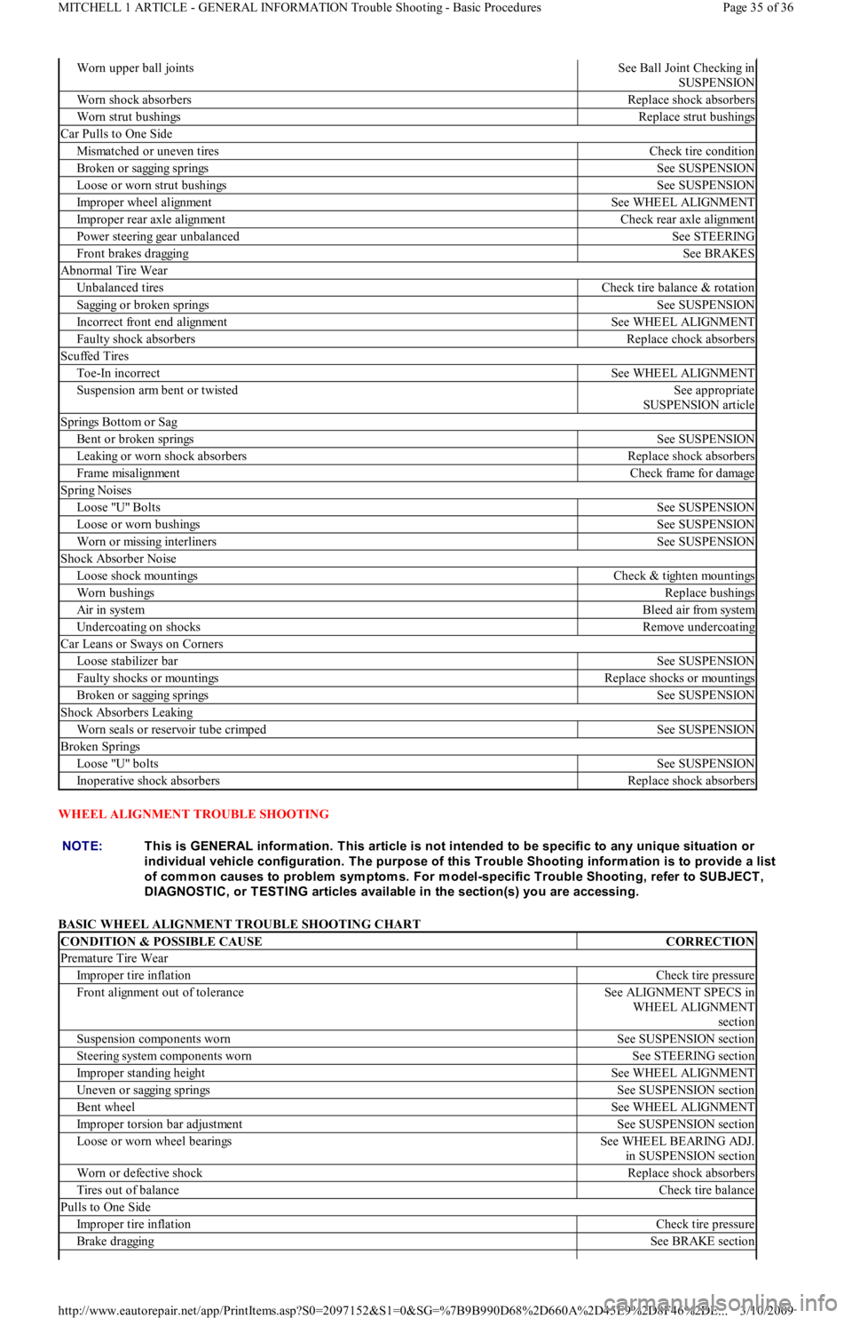
WHEEL ALIGNMENT TROUBLE SHOOTING
BASIC WHEEL ALIGNMENT TROUBLE SHOOTING CHART
Worn upper ball jointsSee Ball Joint Checking in
SUSPENSION
Worn shock absorbersReplace shock absorbers
Worn strut bushingsReplace strut bushings
Car Pulls to One Side
Mismatched or uneven tiresCheck tire condition
Broken or sagging springsSee SUSPENSION
Loose or worn strut bushingsSee SUSPENSION
Improper wheel alignmentSee WHEEL ALIGNMENT
Improper rear axle alignmentCheck rear axle alignment
Power steering gear unbalancedSee STEERING
Front brakes draggingSee BRAKES
Abnormal Tire Wear
Unbalanced tiresCheck tire balance & rotation
Sagging or broken springsSee SUSPENSION
Incorrect front end alignmentSee WHEEL ALIGNMENT
Faulty shock absorbersReplace chock absorbers
Scuffed Tires
Toe-In incorrectSee WHEEL ALIGNMENT
Suspension arm bent or twistedSee appropriate
SUSPENSION article
Springs Bottom or Sag
Bent or broken springsSee SUSPENSION
Leaking or worn shock absorbersReplace shock absorbers
Frame misalignmentCheck frame for damage
Spring Noises
Lo o se "U" Bo l t sSee SUSPENSION
Loose or worn bushingsSee SUSPENSION
Worn or missing interlinersSee SUSPENSION
Shock Absorber Noise
Loose shock mountingsCheck & tighten mountings
Worn bushingsReplace bushings
Air in systemBleed air from system
Undercoating on shocksRemove undercoating
Car Leans or Sways on Corners
Loose stabilizer barSee SUSPENSION
Faulty shocks or mountingsReplace shocks or mountings
Broken or sagging springsSee SUSPENSION
Shock Absorbers Leaking
Worn seals or reservoir tube crimpedSee SUSPENSION
Broken Springs
Lo o se "U" b o l t sSee SUSPENSION
Inoperative shock absorbersReplace shock absorbers
NOTE:This is GENERAL inform ation. This article is not intended to be specific to any unique situation or
individual vehicle configuration. T he purpose of this T rouble Shooting inform ation is to provide a list
of com m on causes to problem sym ptom s. For m odel-specific T rouble Shooting, refer to SUBJECT ,
DIAGNOST IC, or T EST ING articles available in the section(s) you are accessing.
CONDITION & POSSIBLE CAUSECORRECTION
Premature Tire Wear
Improper tire inflationCheck tire pressure
Front alignment out of toleranceSee ALIGNMENT SPECS in
WHEEL ALIGNMENT
section
Suspension components wornSee SUSPENSION section
Steering system components wornSee STEERING section
Improper standing heightSee WHEEL ALIGNMENT
Uneven or sagging springsSee SUSPENSION section
Bent wheelSee WHEEL ALIGNMENT
Improper torsion bar adjustmentSee SUSPENSION section
Loose or worn wheel bearingsSee WHEEL BEARING ADJ.
in SUSPENSION section
Worn or defective shockReplace shock absorbers
Tires out of balanceCheck tire balance
Pulls to One Side
Improper tire inflationCheck tire pressure
Brake draggingSee BRAKE section
Page 35 of 36 MITCHELL 1 ARTICLE - GENERAL INFORMATION Trouble Shooting - Basic Procedures
3/10/2009 http://www.eautorepair.net/app/PrintItems.asp?S0=2097152&S1=0&SG=%7B9B990D68%2D660A%2D45E9%2D8F46%2DE
...
Page 249 of 454
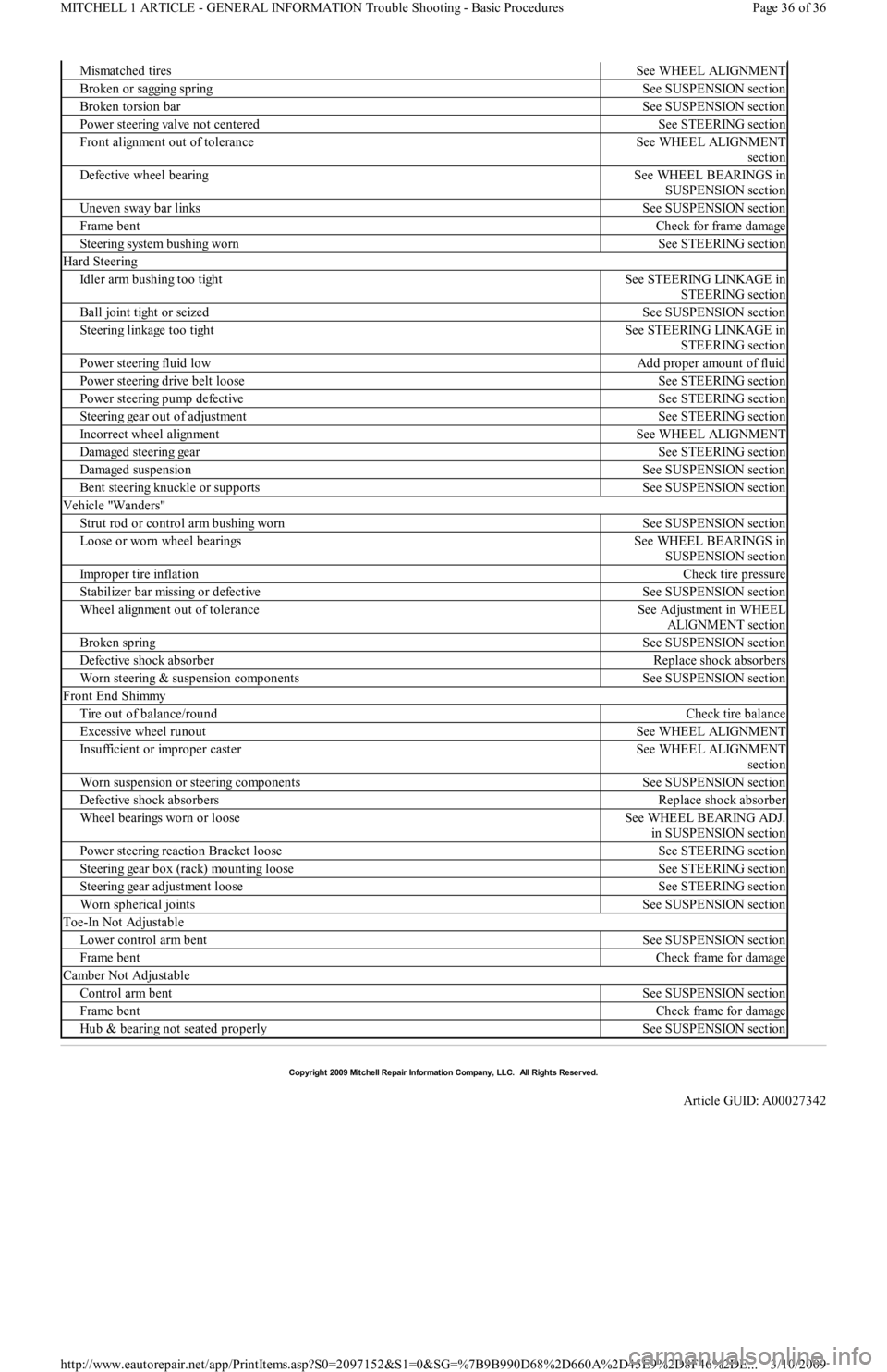
Mismatched tiresSee WHEEL ALIGNMENT
Broken or sagging springSee SUSPENSION section
Broken torsion barSee SUSPENSION section
Power steering valve not centeredSee STEERING section
Front alignment out of toleranceSee WHEEL ALIGNMENT
section
Defective wheel bearingSee WHEEL BEARINGS in
SUSPENSION section
Uneven sway bar linksSee SUSPENSION section
Frame bentCheck for frame damage
Steering system bushing wornSee STEERING section
Hard Steering
Idler arm bushing too tightSee STEERING LINKAGE in
STEERING section
Ball joint tight or seizedSee SUSPENSION section
Steering linkage too tightSee STEERING LINKAGE in
STEERING section
Power steering fluid lowAdd proper amount of fluid
Power steering drive belt looseSee STEERING section
Power steering pump defectiveSee STEERING section
Steering gear out of adjustmentSee STEERING section
Incorrect wheel alignmentSee WHEEL ALIGNMENT
Damaged steering gearSee STEERING section
Damaged suspensionSee SUSPENSION section
Bent steering knuckle or supportsSee SUSPENSION section
Vehicle "Wanders"
Strut rod or control arm bushing wornSee SUSPENSION section
Loose or worn wheel bearingsSee WHEEL BEARINGS in
SUSPENSION section
Improper tire inflationCheck tire pressure
Stabilizer bar missing or defectiveSee SUSPENSION section
Wheel alignment out of toleranceSee Adjustment in WHEEL
ALIGNMENT section
Broken springSee SUSPENSION section
Defective shock absorberReplace shock absorbers
Worn steering & suspension componentsSee SUSPENSION section
Front End Shimmy
Tire out of balance/roundCheck tire balance
Excessive wheel runoutSee WHEEL ALIGNMENT
Insufficient or improper casterSee WHEEL ALIGNMENT
section
Worn suspension or steering componentsSee SUSPENSION section
Defective shock absorbersReplace shock absorber
Wheel bearings worn or looseSee WHEEL BEARING ADJ.
in SUSPENSION section
Power steering reaction Bracket looseSee STEERING section
Steering gear box (rack) mounting looseSee STEERING section
Steering gear adjustment looseSee STEERING section
Worn spherical jointsSee SUSPENSION section
Toe-In Not Adjustable
Lower control arm bentSee SUSPENSION section
Frame bentCheck frame for damage
Camber Not Adjustable
Control arm bentSee SUSPENSION section
Frame bentCheck frame for damage
Hub & bearing not seated properlySee SUSPENSION section
Copyr ight 2009 Mitchell Repair Information Company, LLC. All Rights Reserved.
Article GUID: A00027342
Page 36 of 36 MITCHELL 1 ARTICLE - GENERAL INFORMATION Trouble Shooting - Basic Procedures
3/10/2009 http://www.eautorepair.net/app/PrintItems.asp?S0=2097152&S1=0&SG=%7B9B990D68%2D660A%2D45E9%2D8F46%2DE
...