turn signal FORD FESTIVA 1991 Service Manual
[x] Cancel search | Manufacturer: FORD, Model Year: 1991, Model line: FESTIVA, Model: FORD FESTIVA 1991Pages: 454, PDF Size: 9.53 MB
Page 2 of 454
Back To Article
INST RUMENT PANEL
1991 ACCESSORIES & SAFET Y EQUIPMENT Ford Motor Co. Switches & Instrum ent Panels - Standard
DESCRIPTION & OPERATION
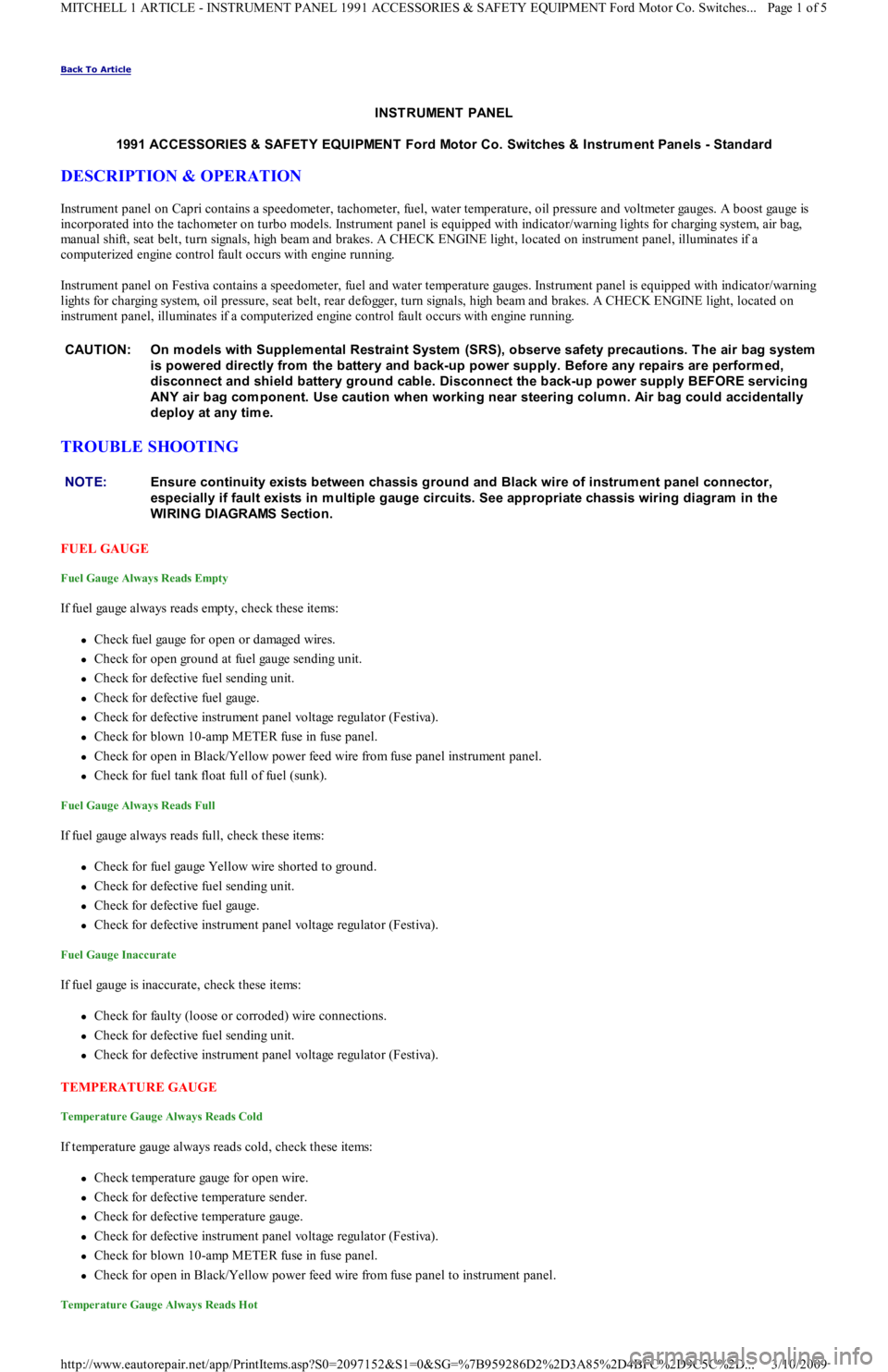
Instrument panel on Capri contains a speedometer, tachometer, fuel, water temperature, oil pressure and voltmeter gauges. A boost gauge is
incorporated into the tachometer on turbo models. Instrument panel is equipped with indicator/warning lights for charging system, air b ag,
manual shift, seat belt, turn signals, high beam and brakes. A CHECK ENGINE light, located on instrument panel, illuminates if a
computerized engine control fault occurs with engine running.
Instrument panel on Festiva contains a speedometer, fuel and water temperature gauges. Instrument panel is equipped with indicator/warning
lights for charging system, oil pressure, seat belt, rear defogger, turn signals, high beam and brakes. A CHECK ENGINE light, located on
instrument panel, illuminates if a computerized engine control fault occurs with engine running.
TROUBLE SHOOTING
FUEL GAUGE
Fuel Gauge Always Reads Empty
If fuel gauge always reads empty, check these items:
Check fuel gauge for open or damaged wires.
Check for open ground at fuel gauge sending unit.
Check for defective fuel sending unit.
Check for defective fuel gauge.
Check for defective instrument panel voltage regulator (Festiva).
Check for blown 10-amp METER fuse in fuse panel.
Check for open in Black/Yellow power feed wire from fuse panel instrument panel.
Check for fuel tank float full of fuel (sunk).
Fuel Gauge Always Reads Full
If fuel gauge always reads full, check these items:
Check for fuel gauge Yellow wire shorted to ground.
Check for defective fuel sending unit.
Check for defective fuel gauge.
Check for defective instrument panel voltage regulator (Festiva).
Fuel Gauge Inaccurate
If fuel gauge is inaccurate, check these items:
Check for faulty (loose or corroded) wire connections.
Check for defective fuel sending unit.
Check for defective instrument panel voltage regulator (Festiva).
TEMPERATURE GAUGE
Temperature Gauge Always Reads Cold
If temperature gauge always reads cold, check these items:
Check temperature gauge for open wire.
Check for defective temperature sender.
Check for defective temperature gauge.
Check for defective instrument panel voltage regulator (Festiva).
Check for blown 10-amp METER fuse in fuse panel.
Check for open in Black/Yellow power feed wire from fuse panel to instrument panel.
Temperature Gauge Always Reads Hot
CAUT ION: On m odels with Supplem ental Restraint System (SRS), observe safety precautions. T he air bag system
is powered directly from the battery and back-up power supply. Before any repairs are perform ed,
disconnect and shield battery ground cable. Disconnect the back-up power supply BEFORE servicing
ANY air bag com ponent. Use caution when working near steering colum n. Air bag could accidentally
deploy at any tim e.
NOTE:Ensure continuity exists between chassis ground and Black wire of instrum ent panel connector,
especially if fault exists in m ultiple gauge circuits. See appropriate chassis wiring diagram in the
WIRING DIAGRAMS Section.
Page 1 of 5 MITCHELL 1 ARTICLE - INSTRUMENT PANEL 1991 ACCESSORIES & SAFETY EQUIPMENT Ford Motor Co. Switches
...
3/10/2009 http://www.eautorepair.net/app/PrintItems.asp?S0=2097152&S1=0&SG=%7B959286D2%2D3A85%2D4BFC%2D9C5C%2D
...
Page 4 of 454
Turbo Boost Gauge Always Reads High
If turbo boost gauge always reads high, check these items:
Check for damaged White/Black signal wire.
Check for defective boost sensing unit.
Check for defective boost gauge.
Turbo Boost Gauge Inaccurate
If turbo boost gauge is inaccurate, check these items:
Check for loose or corroded connections.
Check for defective boost sensing unit.
Check for defective boost gauge.
TESTING
FUEL GAUGE SENDING UNIT
Capri
Remove rear seat cushion. Disconnect fuel pump/fuel gauge sending unit electrical connector at access cover. Turn ignition on. Fuel gauge
should read empty. Using a jumper wire, connect Yellow fuel gauge wire of vehicle harness connector to ground. Fuel gauge should read full.
If fuel gauge operates as specified, replace fuel gauge sending unit.
Festiva
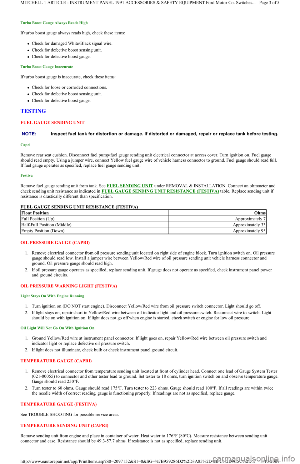
Remove fuel gauge sending unit from tank. See FUEL SENDING UNIT under REMOVAL & INSTALLATION. Connect an ohmmeter and
check sending unit resistance as indicated in FUEL GAUGE SENDING UNIT RESISTANCE (FESTIVA)
table. Replace sending unit if
resistance is drastically different than specification.
FUEL GAUGE SENDING UNIT RESISTANCE (FESTIVA)
OIL PRESSURE GAUGE (CAPRI)
1. Remove electrical connector from oil pressure sending unit located on right side of engine block. Turn ignition switch on. Oil pressure
gauge should read low. Install a jumper wire between Yellow/Red wire of oil pressure sending unit vehicle harness connector and
ground. Oil pressure gauge should read high.
2. If oil pressure gauge operates as specified, replace sending unit. If gauge does not operate as specified, check instrument panel power
and ground circuits.
OIL PRESSURE WARNING LIGHT (FESTIVA)
Light Stays On With Engine Running
1. Turn ignition on (DO NOT start engine). Disconnect Yellow/Red wire from oil pressure switch connector. Light should go off.
2. If light stays on, repair short in Yellow/Red wire between oil indicator light and oil pressure switch. Reconnect wire to switch. Light
should be on with ignition on. If light does not go off when engine is started, check switch or engine for low oil pressure.
Oil Light Will Not Go On With Ignition On
1. Ground Yellow/Red wire at instrument panel connector. If light goes on, repair Yellow/Red wire between oil pressure switch and
indicator light or replace defective oil pressure switch.
2. If light does not illuminate, check bulb or check instrument panel ground circuit.
TEMPERATURE GAUGE (CAPRI)
1. Remove electrical connector from temperature sending unit located at front of cylinder head. Connect one lead of Gauge System Tester
(021-00055) to connector and other tester lead to ground. Set tester to 18 ohms, turn ignition switch on and observe temperature gauge.
Gauge should read 250°F.
2. Turn tester to 60 ohms. Gauge should read 175°F. Turn tester to 223 ohms. Gauge should read 100°F. If all readings are within twice
the needle width of correct reading, gauge is functioning properly. If readings are not as specified, replace gauge.
TEMPERATURE GAUGE (FESTIVA)
See TROUBLE SHOOTING for possible service areas.
TEMPERATURE SENDING UNIT (CAPRI)
Remove sending unit from engine and place in container of water. Heat water to 176°F (80°C). Measure resistance between sending unit
connector and case. Resistance should be 49.3-57.7 ohms. If resistance is not as specified, replace sending unit. NOTE:Inspect fuel tank for distortion or dam age. If distorted or dam aged, repair or replace tank before testing.
Float PositionOhms
Full Position (Up)Approximately 7
Half-Full Position (Middle)Approximately 33
Empty Position (Down)Approximately 95
Page 3 of 5 MITCHELL 1 ARTICLE - INSTRUMENT PANEL 1991 ACCESSORIES & SAFETY EQUIPMENT Ford Motor Co. Switches
...
3/10/2009 http://www.eautorepair.net/app/PrintItems.asp?S0=2097152&S1=0&SG=%7B959286D2%2D3A85%2D4BFC%2D9C5C%2D
...
Page 18 of 454
Back To Article
ST EERING COLUMN SWIT CHES
1991 ACCESSORIES & SAFET Y EQUIPMENT Ford Motor Co. Steering Colum n Switches
DESCRIPTION & OPERATION
DISABLING AIR BAG SYSTEM
To disable SRS, disconnect battery cable. Unplug back-up power supply 3-way harness connector. System is now disabled. Back-up power
supply is mounted to inside of instrument panel, left of glove box opening. Glove box door must be opened past its stops and lowered toward
floor to access back-up power supply.
ACTIVATING AIR BAG SYSTEM
To activate SRS, reconnect back-up power supply connector and negative battery cable. From passenger's side of vehicle, turn ignition switch
to RUN position. System is now activated. Check AIR BAG light to ensure system is functioning properly.
TESTING
HAZARD WARNING SWITCH & TURN SIGNAL SWITCH
Capri
1. Remove steering column covers to access turn signal/hazard switch connectors. Turn ignition on. Using a 12-volt test light, ensure
battery voltage is present at Green/Red and Green/Yellow wires at turn signal/hazard switch connectors. If battery voltage is not present,
check METER and HAZARD fuses. Also check hazard and turn signal flasher units and replace as necessary.
2. If battery voltage is present at Green/Red and Green/Yellow wires, place turn signal switch in RIGHT position. Check both Green/White
wires at switch connector. Test light should flash on and off in constant cycles.
3. Place turn signal switch in LEFT position. Check both Green/Black wires at switch connector. Test light should flash on and off in
constant cycles. If turn signal/hazard switch does not function as specified, replace switch.
Festiva
1. Remove steering column covers to access turn signal/hazard switch connectors. Turn ignition on. Using a 12-volt test light, ensure
battery voltage is present at White/Black and Black/Yellow wires at hazard and turn signal switch connectors. If battery voltage is not
present, check METER and HAZARD fuses.
2. If battery voltage is present at White/Black and Black/Yellow wires, place turn signal/hazard switch in RIGHT position. Check
Green/Black wire at switch connector. Test light should flash on and off in constant cycles.
3. Place turn signal/hazard switch in LEFT position. Check Green/White wire at switch connector. Test light should flash on and off in
constant cycles. If turn signal/hazard switch does not function as specified, replace switch.
HEADLIGHT SWITCH
Capri
1. Remove instrument panel bezel to access switch connector. See HEADLIGHT SWITCH under REMOVAL & INSTALLATION.
Disconnect switch electrical connector. Measure voltage between Red and Red/White wires of headlight switch vehicle harness and
ground. If battery voltage is present, go to next step. If battery voltage is not present, check HEAD and MAIN fuses and Red and
Red/White wires between switch and fuse block.
2. Press headlight switch to first position. Using a self powered test light or ohmmeter, check continuity between switch terminals which
correspond to Red and Red/Green wires of vehicle harness connector. Continuity should not exist. If continuity exists, replace switch.
3. Press headlight switch to second position. Check continuity between switch terminals which correspond with the Red and Red/Green
wires of vehicle harness connector. Continuity should exist. If switch does not function as described, replace headlight switch. If swit ch
functions as described but headlights do not work, go to next step.
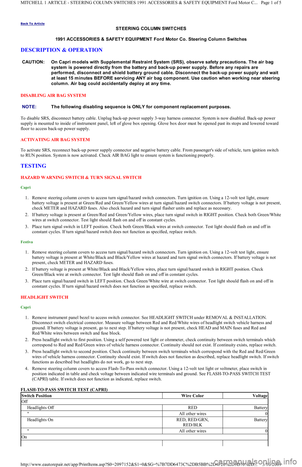
4. Remove steering column covers to access Flash-To-Pass switch connector. Using a 12-volt test light or voltmeter, place switch in
position indicated in table and check voltage between indicated wire terminals and ground. See FLASH-TO-PASS SWITCH TEST
(CAPRI) table. If switch does not function as indicated, replace switch.
FLASH-TO-PASS SWITCH TEST (CAPRI) CAUTION: On Capri m odels with Supplem ental Restraint System (SRS), observe safety precautions. T he air bag
system is powered directly from the battery and back-up power supply. Before any repairs are
perform ed, disconnect and shield battery ground cable. Disconnect the back-up power supply and wait
at least 15 m inutes BEFORE servicing ANY air bag com ponent. Use caution when working near steering
colum n. Air bag could accidentally deploy at any tim e.
NOTE:T he following disabling sequence is ONLY for com ponent replacem ent purposes.
Switch PositionWire ColorVoltage
Off
Headlights OffREDBattery
"All other wires0
Headlights OnRED, RED/GRN,
RED/BLKBattery
"All other wires0
On
Page 1 of 5 MITCHELL 1 ARTICLE - STEERING COLUMN SWITCHES 1991 ACCESSORIES & SAFETY EQUIPMENT Ford Motor C
...
3/10/2009 http://www.eautorepair.net/app/PrintItems.asp?S0=2097152&S1=0&SG=%7B7DD6473C%2DB5BB%2D4F20%2D9D70%2D
...
Page 21 of 454
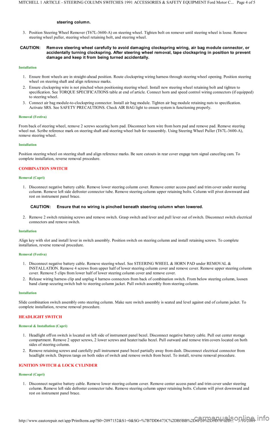
3. Position Steering Wheel Remover (T67L-3600-A) on steering wheel. Tighten bolt on remover until steering wheel is loose. Remove
steering wheel puller, steering wheel retaining bolt, and steering wheel.
Installation
1. Ensure front wheels are in straight-ahead position. Route clockspring wiring harness through steering wheel opening. Position steering
wheel on steering shaft and align reference marks.
2. Ensure clockspring wire is not pinched when positioning steering wheel. Install new steering wheel retaining bolt and tighten to
specification. See TORQUE SPECIFICATIONS table at end of article. Connect horn and speed control wiring connectors (if equipped)
to steering wheel.
3. Connect air bag module-to-clockspring connector. Install air bag module. Tighten air bag module retaining nuts to specification.
Activate SRS. See SAFETY PRECAUTIONS. Check AIR BAG light to ensure system is functioning properly.
Removal (Festiva)
From back of steering wheel, remove 2 screws securing horn pad. Disconnect horn wire from horn pad and remove pad. Remove steering
wheel nut. Scribe reference mark on steering shaft and steering wheel hub for reassembly. Using Steering Wheel Puller (T67L-3600-A),
remove steering wheel.
Installation
Position steering wheel on steering shaft and align reference marks. Be sure cutouts in rear cover engage turn signal canceling cam. To
complete installation, reverse removal procedure.
COMBINATION SW ITCH
Removal (Capri)
1. Disconnect negative battery cable. Remove lower steering column cover. Remove center access panel and trim cover under steering
column. Remove left side defroster connector tube. Remove steering column upper retaining bolts. Column will pivot downward and
rest on instrument panel brace.
2. Remove 2 switch retaining screws and remove switch. Grasp switch and lever and pull lever out of switch. Disconnect switch electrical
connectors and remove switch.
Installation
Align key with slot and install lever in switch assembly. Position switch on steering column and install retaining screws. To complete
installation, reverse removal procedure.
Removal (Festiva)
1. Disconnect negative battery cable. Remove steering wheel. See STEERING WHEEL & HORN PAD under REMOVAL &
INSTALLATION. Remove 4 screws from upper half of lower steering column cover and remove cover. Remove upper steering column
cover. Remove 5 clips from lower half of lower steering column cover and remove cover.
2. Release wiring harness clip and unplug 4 harness connectors from back of combination switch. From below steering column, loosen
band clamp securing switch hub to steering column jacket. Pull switch assembly from steering column.
Installation
Slide combination switch assembly onto steering column. Make sure switch assembly is seated and level against end of column jacket. To
complete installation, reverse removal procedure.
HEADLIGHT SWITCH
Removal & Installation (Capri)
1. Headlight off/on switch is located on left side of instrument panel bezel. Disconnect negative battery cable. Pull out center storage
compartment. Remove 2 upper screws, 2 lower screws and heater/radio bezel. Pull outward and remove trim covers located on both
sides of steering column.
2. Remove retaining screws and carefully pull instrument panel bezel partially away from dash. Disconnect electrical connector from
headlight switch. Depress tangs on both sides of switch and remove switch from bezel. To install, reverse removal procedure.
IGNITION SWITCH & LOCK CYLINDER
Removal (Capri)
1. Disconnect negative battery cable. Remove lower steering column cover. Remove center access panel and trim cover under steering
column. Remove left side defroster connector tube. Remove steering column upper retaining bolts. Column will pivot downward and
rest on instrument panel brace. steering colum n.
CAUT ION: Rem ove steering wheel carefully to avoid dam aging clockspring wiring, air bag m odule connector, or
accidentally turning clockspring. After steering wheel rem oval, tape clockspring in position to prevent
dam age and keep it from being turned accidentally.
CAUTION: Ensure that no wiring is pinched beneath steering colum n when lowered.
Page 4 of 5 MITCHELL 1 ARTICLE - STEERING COLUMN SWITCHES 1991 ACCESSORIES & SAFETY EQUIPMENT Ford Motor C
...
3/10/2009 http://www.eautorepair.net/app/PrintItems.asp?S0=2097152&S1=0&SG=%7B7DD6473C%2DB5BB%2D4F20%2D9D70%2D
...
Page 22 of 454
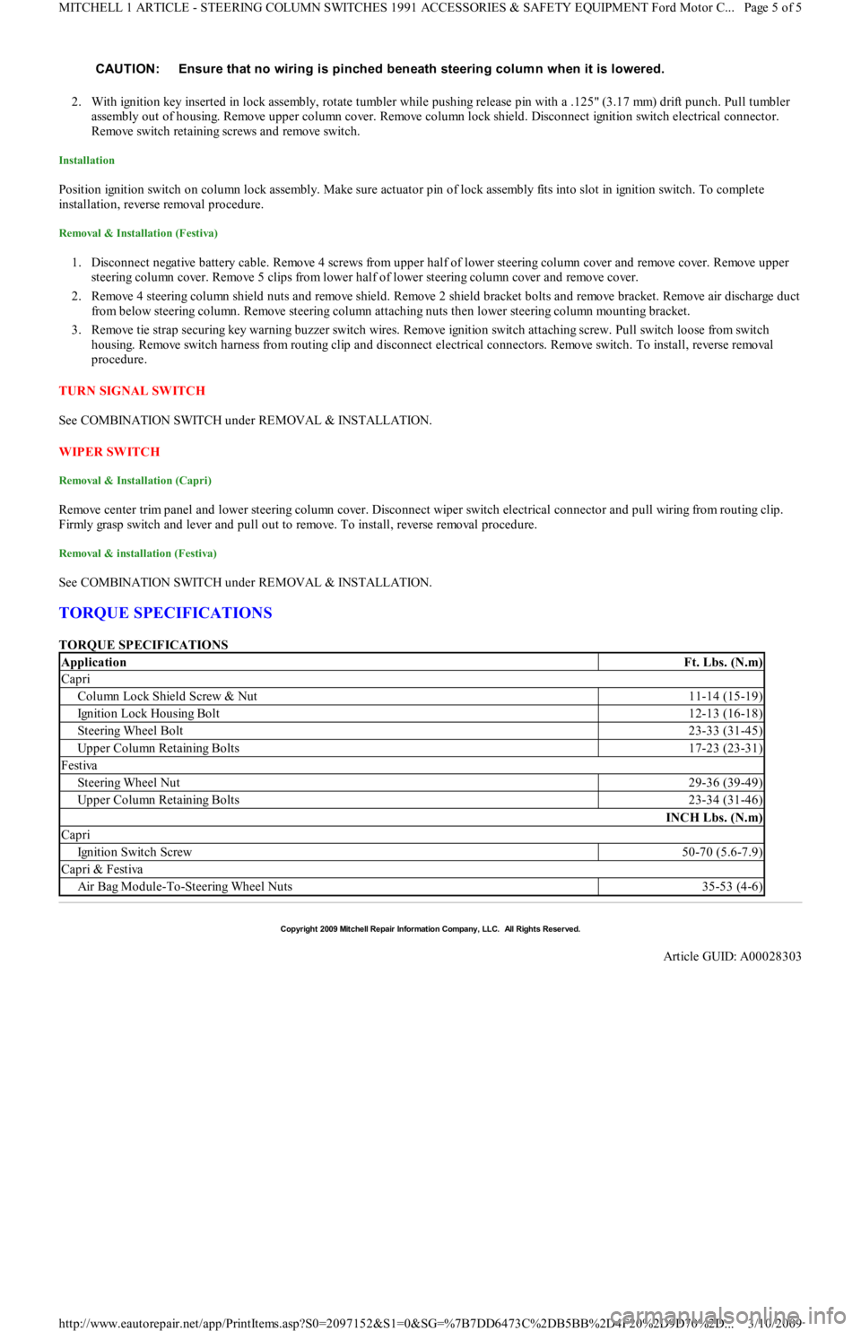
2. With ignition key inserted in lock assembly, rotate tumbler while pushing release pin with a .125" (3.17 mm) drift punch. Pull tumbler
assembly out of housing. Remove upper column cover. Remove column lock shield. Disconnect ignition switch electrical connector.
Remove switch retaining screws and remove switch.
Installation
Position ignition switch on column lock assembly. Make sure actuator pin of lock assembly fits into slot in ignition switch. To complete
installation, reverse removal procedure.
Removal & Installation (Festiva)
1. Disconnect negative battery cable. Remove 4 screws from upper half of lower steering column cover and remove cover. Remove upper
steering column cover. Remove 5 clips from lower half of lower steering column cover and remove cover.
2. Remove 4 steering column shield nuts and remove shield. Remove 2 shield bracket bolts and remove bracket. Remove air discharge duct
from below steering column. Remove steering column attaching nuts then lower steering column mounting bracket.
3. Remove tie strap securing key warning buzzer switch wires. Remove ignition switch attaching screw. Pull switch loose from switch
housing. Remove switch harness from routing clip and disconnect electrical connectors. Remove switch. To install, reverse removal
procedure.
TURN SIGNAL SWITCH
See COMBINATION SWITCH under REMOVAL & INSTALLATION.
WIPER SWITCH
Removal & Installation (Capri)
Remove center trim panel and lower steering column cover. Disconnect wiper switch electrical connector and pull wiring from routing clip.
Firmly grasp switch and lever and pull out to remove. To install, reverse removal procedure.
Removal & installation (Festiva)
See COMBINATION SWITCH under REMOVAL & INSTALLATION.
TORQUE SPECIFICATIONS
TORQUE SPECIFICATIONS CAUTION: Ensure that no wiring is pinched beneath steering colum n when it is lowered.
ApplicationFt. Lbs. (N.m)
Capri
Column Lock Shield Screw & Nut11-14 (15-19)
Ignition Lock Housing Bolt12-13 (16-18)
Steering Wheel Bolt23-33 (31-45)
Upper Column Retaining Bolts17-23 (23-31)
Festiva
Steering Wheel Nut29-36 (39-49)
Upper Column Retaining Bolts23-34 (31-46)
INCH Lbs. (N.m)
Capri
Ign it io n Swit ch Screw50-70 (5.6-7.9)
Capri & Festiva
Air Bag Module-To-Steering Wheel Nuts35-53 (4-6)
Copyr ight 2009 Mitchell Repair Information Company, LLC. All Rights Reserved.
Article GUID: A00028303
Page 5 of 5 MITCHELL 1 ARTICLE - STEERING COLUMN SWITCHES 1991 ACCESSORIES & SAFETY EQUIPMENT Ford Motor C
...
3/10/2009 http://www.eautorepair.net/app/PrintItems.asp?S0=2097152&S1=0&SG=%7B7DD6473C%2DB5BB%2D4F20%2D9D70%2D
...
Page 46 of 454
Back To Article
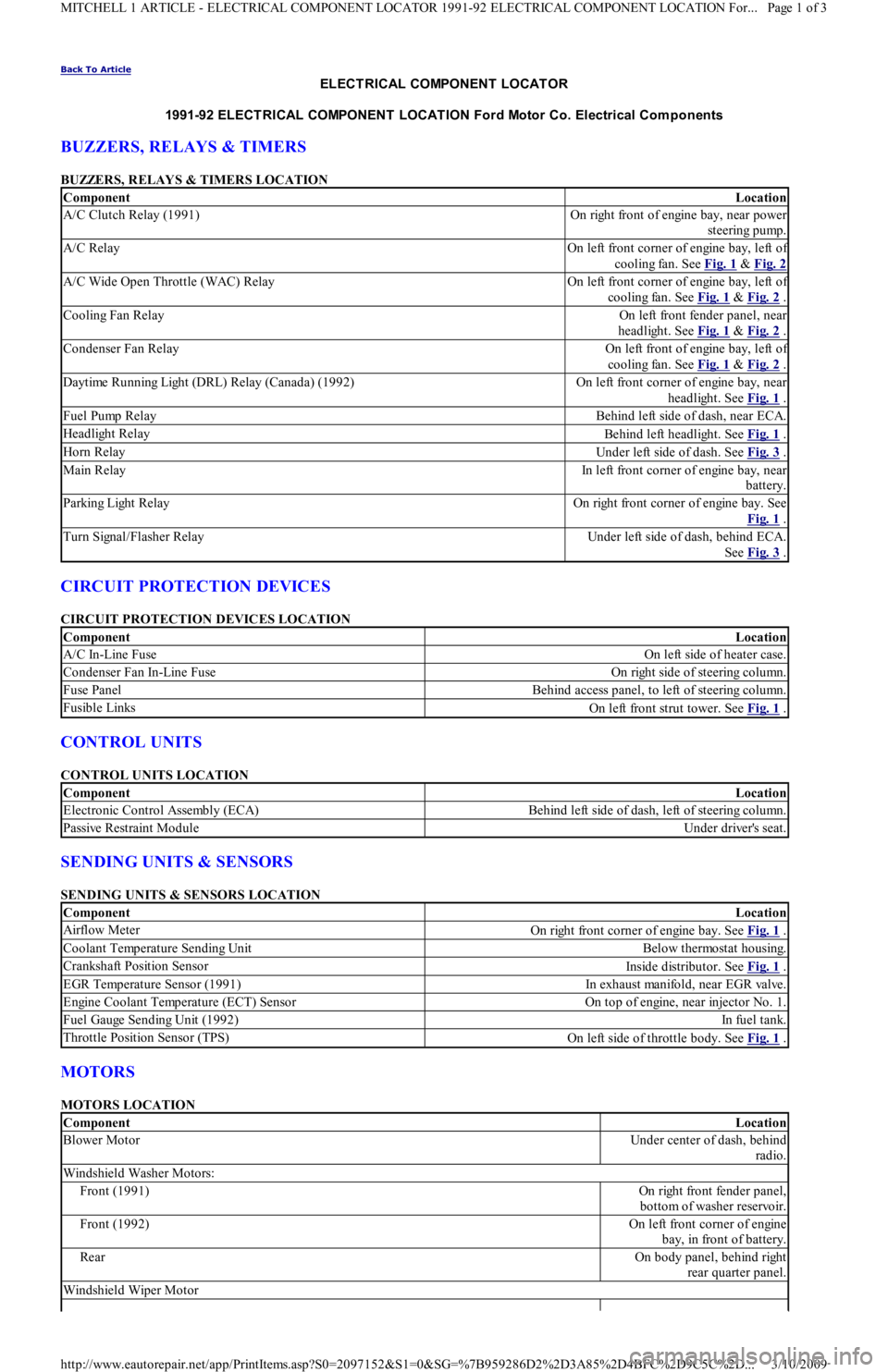
ELECT RICAL COMPONENT LOCAT OR
1991-92 ELECT RICAL COMPONENT LOCAT ION Ford Motor Co. Electrical Com ponents
BUZZERS, RELAYS & TIMERS
BUZZERS, RELAYS & TIMERS LOCATION
CIRCUIT PROTECTION DEVICES
CIRCUIT PROTECTION DEVICES LOCATION
CONTROL UNITS
CONTROL UNITS LOCATION
SENDING UNITS & SENSORS
SENDING UNITS & SENSORS LOCATION
MOTORS
MOTORS LOCATION
ComponentLocation
A/C Clutch Relay (1991)On right front of engine bay, near power
steering pump.
A/C RelayOn left front corner of engine bay, left of
cooling fan. See Fig. 1
& Fig. 2
A/C Wide Open Throttle (WAC) RelayOn left front corner of engine bay, left of
cooling fan. See Fig. 1
& Fig. 2 .
Cooling Fan RelayOn left front fender panel, near
headlight. See Fig. 1
& Fig. 2 .
Condenser Fan RelayOn left front of engine bay, left of
cooling fan. See Fig. 1
& Fig. 2 .
Daytime Running Light (DRL) Relay (Canada) (1992)On left front corner of engine bay, near
headlight. See Fig. 1
.
Fuel Pump RelayBehind left side of dash, near ECA.
Headlight RelayBehind left headlight. See Fig. 1 .
Horn RelayUnder left side of dash. See Fig. 3 .
Main RelayIn left front corner of engine bay, near
battery.
P a r kin g Ligh t R e l a yOn right front corner of engine bay. See
Fig. 1
.
Turn Signal/Flasher RelayUnder left side of dash, behind ECA.
See Fig. 3
.
ComponentLocation
A/C In-Line FuseOn left side of heater case.
Condenser Fan In-Line FuseOn right side of steering column.
Fuse PanelBehind access panel, to left of steering column.
Fusible LinksOn left front strut tower. See Fig. 1 .
ComponentLocation
Electronic Control Assembly (ECA)Behind left side of dash, left of steering column.
Passive Restraint ModuleUnder driver's seat.
ComponentLocation
Airflow MeterOn right front corner of engine bay. See Fig. 1 .
Coolant Temperature Sending UnitBelow thermostat housing.
Crankshaft Position SensorInside distributor. See Fig. 1 .
EGR Temperature Sensor (1991)In exhaust manifold, near EGR valve.
Engine Coolant Temperature (ECT) SensorOn top of engine, near injector No. 1.
Fuel Gauge Sending Unit (1992)In fu el t an k.
Throttle Position Sensor (TPS)On left side of throttle body. See Fig. 1 .
ComponentLocation
Blower MotorUnder center of dash, behind
radio.
Windshield Washer Motors:
Front (1991)On right front fender panel,
bottom of washer reservoir.
Front (1992)On left front corner of engine
bay, in front of battery.
RearOn body panel, behind right
rear quarter panel.
Windshield Wiper Motor
Page 1 of 3 MITCHELL 1 ARTICLE - ELECTRICAL COMPONENT LOCATOR 1991-92 ELECTRICAL COMPONENT LOCATION For...
3/10/2009 http://www.eautorepair.net/app/PrintItems.asp?S0=2097152&S1=0&SG=%7B959286D2%2D3A85%2D4BFC%2D9C5C%2D
...
Page 50 of 454
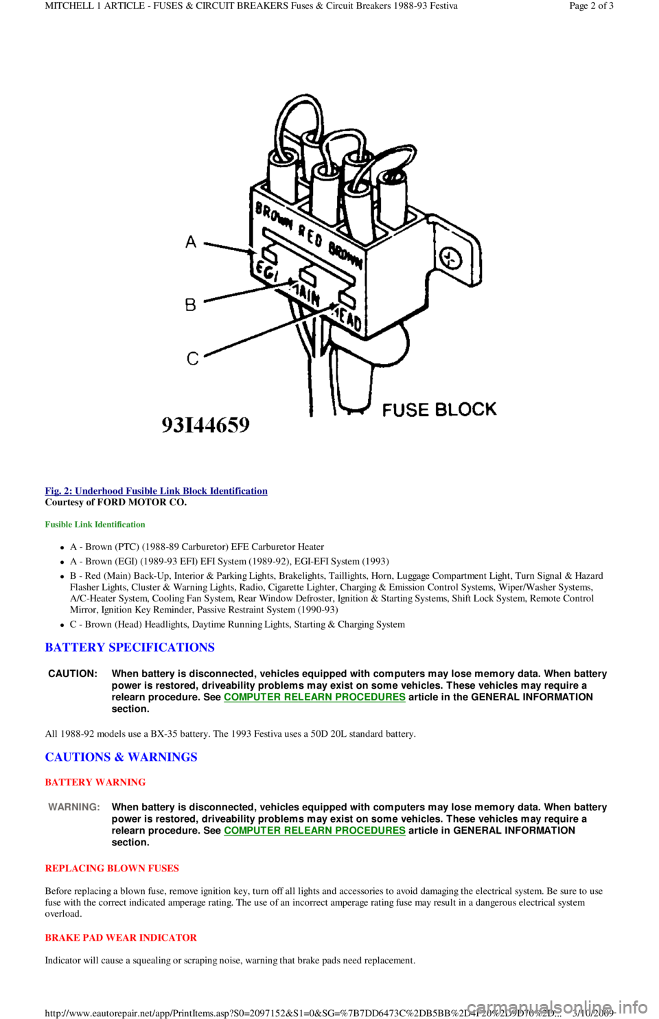
Fig. 2: Underhood Fusible Link Block Identification
Courtesy of FORD MOTOR CO.
Fusible Link Identification
A - Brown (PTC) (1988-89 Carburetor) EFE Carburetor Heater
A - Brown (EGI) (1989-93 EFI) EFI System (1989-92), EGI-EFI System (1993)
B - Red (Main) Back-Up, Interior & Parking Lights, Brakelights, Taillights, Horn, Luggage Compartment Light, Turn Signal & Hazard
F l a sh e r Ligh t s, C l u st e r & Wa r n in g Ligh t s, R a d io , C iga r e t t e Ligh t e r , C h a r gin g & E missio n C o n t r o l S yst e ms, Wip e r / Wa sh e r S yst e ms,
A/C-Heater System, Cooling Fan System, Rear Window Defroster, Ignition & Starting Systems, Shift Lock System, Remote Control
Mirror, Ignition Key Reminder, Passive Restraint System (1990-93)
C - Brown (Head) Headlights, Daytime Running Lights, Starting & Charging System
BATTERY SPECIFICATIONS
All 1988-92 models use a BX-35 battery. The 1993 Festiva uses a 50D 20L standard battery.
CAUTIONS & WARNINGS
BATTERY WARNING
REPLACING BLOWN FUSES
Before replacing a blown fuse, remove ignition key, turn off all lights and accessories to avoid damaging the electrical system. Be sure to use
fuse with the correct indicated amperage rating. The use of an incorrect amperage rating fuse may result in a dangerous electrical system
overload.
BRAKE PAD WEAR INDICATOR
Indicator will cause a squealing or scraping noise, warning that brake pads need replacement.
CAUT ION: When battery is disconnected, vehicles equipped with com puters m ay lose m em ory data. When battery
power is restored, driveability problem s m ay exist on som e vehicles. T hese vehicles m ay require a
relearn procedure. See COMPUTER RELEARN PROCEDURES
article in the GENERAL INFORMAT ION
section.
WARNING:When battery is disconnected, vehicles equipped with com puters m ay lose m em ory data. When battery
power is restored, driveability problem s m ay exist on som e vehicles. T hese vehicles m ay require a
relearn procedure. See COMPUTER RELEARN PROCEDURES
article in GENERAL INFORMAT ION
section.
Page 2 of 3 MITCHELL 1 ARTICLE - FUSES & CIRCUIT BREAKERS Fuses & Circuit Breakers 1988-93 Festiva
3/10/2009 http://www.eautorepair.net/app/PrintItems.asp?S0=2097152&S1=0&SG=%7B7DD6473C%2DB5BB%2D4F20%2D9D70%2D
...
Page 68 of 454
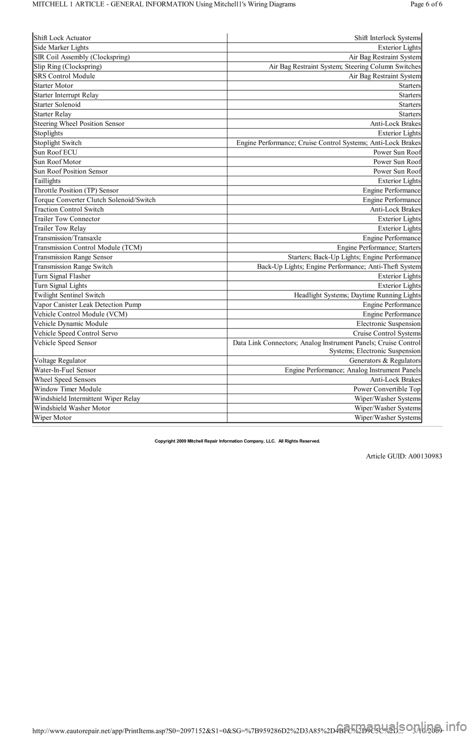
Shift Lock ActuatorShift Interlock Systems
Side Marker LightsExterior Lights
SIR Coil Assembly (Clockspring)Air Bag Restraint System
Slip Ring (Clockspring)Air Bag Restraint System; Steering Column Switches
SRS Control ModuleAir Bag Restraint System
Starter MotorStarters
Starter Interrupt RelayStarters
Starter SolenoidStarters
Starter RelayStarters
Steering Wheel Position SensorAnti-Lock Brakes
StoplightsExterior Lights
Stoplight SwitchEngine Performance; Cruise Control Systems; Anti-Lock Brakes
Sun Roof ECUPower Sun Roof
Sun Roof MotorPower Sun Roof
Sun Roof Position SensorPower Sun Roof
TaillightsExterior Lights
Throttle Position (TP) SensorEngine Performance
Torque Converter Clutch Solenoid/SwitchEngine Performance
Traction Control SwitchAnti-Lock Brakes
Trailer Tow ConnectorExterior Lights
Trailer Tow RelayExterior Lights
Transmission/TransaxleEngine Performance
Transmission Control Module (TCM)Engine Performance; Starters
Transmission Range SensorStarters; Back-Up Lights; Engine Performance
Transmission Range SwitchBack-Up Lights; Engine Performance; Anti-Theft System
Turn Signal FlasherExterior Lights
Tu r n S ign a l Ligh t sExterior Lights
Twilight Sentinel SwitchHeadlight Systems; Daytime Running Lights
Vapor Canister Leak Detection PumpEngine Performance
Vehicle Control Module (VCM)Engine Performance
Vehicle Dynamic ModuleElectronic Suspension
Vehicle Speed Control ServoCruise Control Systems
Vehicle Speed SensorData Link Connectors; Analog Instrument Panels; Cruise Control
Systems; Electronic Suspension
Voltage RegulatorGenerators & Regulators
Water-In-Fuel SensorEngine Performance; Analog Instrument Panels
Wheel Speed SensorsAnti-Lock Brakes
Window Timer ModulePower Convertible Top
Windshield Intermittent Wiper RelayWiper/Washer Systems
Windshield Washer MotorWiper/Washer Systems
Wiper MotorWiper/Washer Systems
Copyr ight 2009 Mitchell Repair Information Company, LLC. All Rights Reserved.
Article GUID: A00130983
Page 6 of 6 MITCHELL 1 ARTICLE - GENERAL INFORMATION Using Mitchell1's Wiring Diagrams
3/10/2009 http://www.eautorepair.net/app/PrintItems.asp?S0=2097152&S1=0&SG=%7B959286D2%2D3A85%2D4BFC%2D9C5C%2D
...
Page 165 of 454
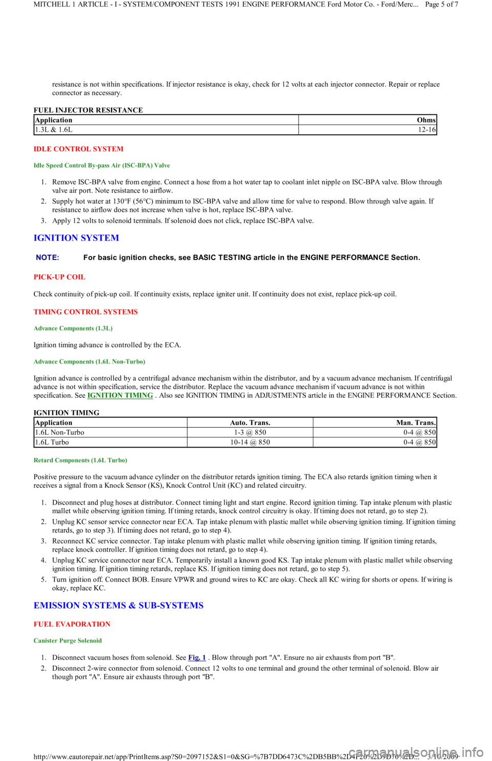
resistance is not within specifications. If injector resistance is okay, check for 12 volts at each injector connector. Repair or replace
connector as necessary.
FUEL INJECTOR RESISTANCE
IDLE CONTROL SYSTEM
Idle Speed Control By-pass Air (ISC-BPA) Valve
1. Remove ISC-BPA valve from engine. Connect a hose from a hot water tap to coolant inlet nipple on ISC-BPA valve. Blow through
valve air port. Note resistance to airflow.
2. Supply hot water at 130°F (56°C) minimum to ISC-BPA valve and allow time for valve to respond. Blow through valve again. If
resistance to airflow does not increase when valve is hot, replace ISC-BPA valve.
3. Apply 12 volts to solenoid terminals. If solenoid does not click, replace ISC-BPA valve.
IGNITION SYSTEM
PICK-UP COIL
Check continuity of pick-up coil. If continuity exists, replace igniter unit. If continuity does not exist, replace pick-up coil.
TIMING CONTROL SYSTEMS
Advance Components (1.3L)
Ignition timing advance is controlled by the ECA.
Advance Components (1.6L Non-Turbo)
Ignition advance is controlled by a centrifugal advance mechanism within the distributor, and by a vacuum advance mechanism. If centrifugal
advance is not within specification, service the distributor. Replace the vacuum advance mechanism if vacuum advance is not within
specification. See IGNITION TIMING
. Also see IGNITION TIMING in ADJUSTMENTS article in the ENGINE PERFORMANCE Section.
IGNITION TIMING
Retard Components (1.6L Turbo)
Positive pressure to the vacuum advance cylinder on the distributor retards ignition timing. The ECA also retards ignition timing when it
receives a signal from a Knock Sensor (KS), Knock Control Unit (KC) and related circuitry.
1. Disconnect and plug hoses at distributor. Connect timing light and start engine. Record ignition timing. Tap intake plenum with plastic
mallet while observing ignition timing. If timing retards, knock control circuitry is okay. If timing does not retard, go to step 2).
2. Unplug KC sensor service connector near ECA. Tap intake plenum with plastic mallet while observing ignition timing. If ignition timing
retards, go to step 3). If timing does not retard, go to step 4).
3. Reconnect KC service connector. Tap intake plenum with plastic mallet while observing ignition timing. If ignition timing retards,
replace knock controller. If ignition timing does not retard, go to step 4).
4. Unplug KC service connector near ECA. Temporarily install a known good KS. Tap intake plenum with plastic mallet while observing
ignition timing. If ignition timing retards, replace KS. If ignition timing does not retard, go to step 5).
5. Turn ignition off. Connect BOB. Ensure VPWR and ground wires to KC are okay. Check all KC wiring for shorts or opens. If wiring is
okay, replace KC.
EMISSION SYSTEMS & SUB-SYSTEMS
FUEL EVAPORATION
Canister Purge Solenoid
1. Disconnect vacuum hoses from solenoid. See Fig. 1 . Blow through port "A". Ensure no air exhausts from port "B".
2. Disconnect 2-wire connector from solenoid. Connect 12 volts to one terminal and ground the other terminal of solenoid. Blow air
though port "A". Ensure air exhausts through port "B".
ApplicationOhms
1.3L & 1.6L12-16
NOTE:For basic ignition checks, see BASIC T EST ING article in the ENGINE PERFORMANCE Section.
ApplicationAuto. Trans.Man. Trans.
1.6L Non-Turbo1-3 @ 8500-4 @ 850
1.6L Turbo10-14 @ 8500-4 @ 850
Page 5 of 7 MITCHELL 1 ARTICLE - I - SYSTEM/COMPONENT TESTS 1991 ENGINE PERFORMANCE Ford Motor Co. - Ford/Merc
...
3/10/2009 http://www.eautorepair.net/app/PrintItems.asp?S0=2097152&S1=0&SG=%7B7DD6473C%2DB5BB%2D4F20%2D9D70%2D
...
Page 168 of 454
Back To Article
G - T EST S W/CODES
1991-92 ENGINE PERFORMANCE Ford Motor Co. Self-Diagnostics
INTRODUCTION
If no faults were found while performing BASIC TESTING , proceed with self-diagnostics. If no fault codes or only pass codes are present
after entering self-diagnostics, proceed to TESTS W/O CODES article in the ENGINE PERFORMANCE Section for diagnosis by symptom
(i.e., ROUGH IDLE, NO START, etc.).
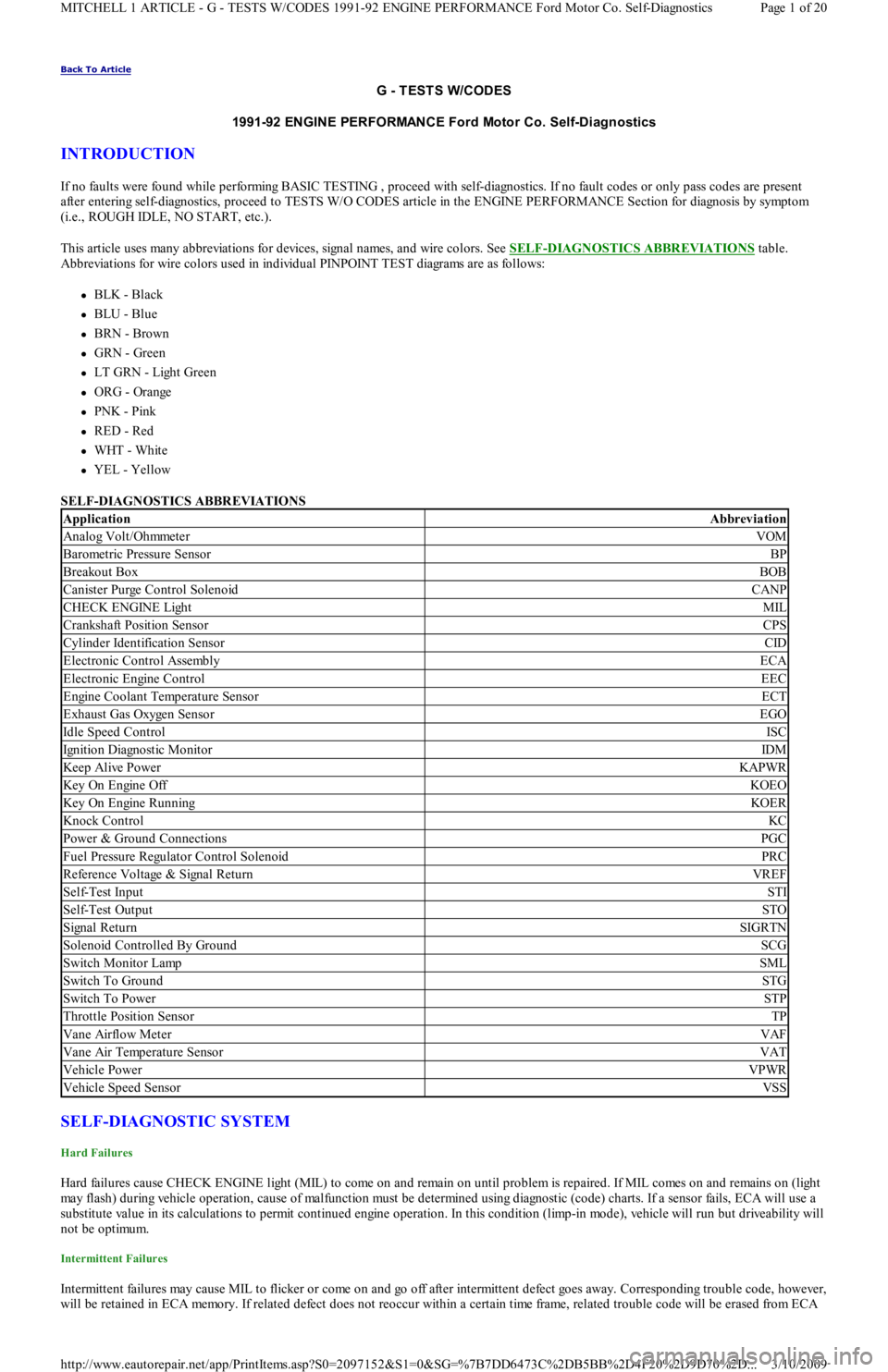
This article uses many abbreviations for devices, signal names, and wire colors. See SELF
-DIAGNOSTICS ABBREVIATIONS table.
Abbreviations for wire colors used in individual PINPOINT TEST diagrams are as follows:
BLK - Black
BLU - Blue
BRN - Brown
GRN - Green
LT GRN - Light Green
ORG - Orange
PNK - Pink
RED - Red
WHT - White
YEL - Yellow
SELF-DIAGNOSTICS ABBREVIATIONS
SELF-DIAGNOSTIC SYSTEM
Hard Failures
Hard failures cause CHECK ENGINE light (MIL) to come on and remain on until problem is repaired. If MIL comes on and remains on (light
may flash) during vehicle operation, cause of malfunction must be determined using diagnostic (code) charts. If a sensor fails, ECA will use a
substitute value in its calculations to permit continued engine operation. In this condition (limp-in mode), vehicle will run but driveability will
not be optimum.
Intermittent Failures
Intermittent failures may cause MIL to flicker or come on and go off after intermittent defect goes away. Corresponding trouble code, however,
will be retained in ECA memory. If related defect does not reoccur within a certain time frame, related trouble code will be erased from ECA
ApplicationAbbreviation
Analog Volt/OhmmeterVOM
Barometric Pressure SensorBP
Breakout BoxBOB
Canister Purge Control SolenoidCANP
CHECK ENGINE LightMIL
Crankshaft Position SensorCPS
Cylinder Identification SensorCID
Electronic Control AssemblyECA
Electronic Engine ControlEEC
Engine Coolant Temperature SensorECT
Exhaust Gas Oxygen SensorEGO
Idle Speed ControlISC
Ignition Diagnostic MonitorIDM
Keep Alive PowerKAPWR
Key On Engine OffKOEO
Key On Engine RunningKOER
Knock ControlKC
Power & Ground ConnectionsPGC
Fuel Pressure Regulator Control SolenoidPRC
Reference Voltage & Signal ReturnVREF
Self-Test InputSTI
Self-Test OutputSTO
Signal ReturnSIGRTN
Solenoid Controlled By GroundSCG
Switch Monitor LampSML
Switch To GroundSTG
Switch To PowerSTP
Throttle Position SensorTP
Vane Airflow MeterVAF
Vane Air Temperature SensorVAT
Vehicle PowerVPWR
Vehicle Speed SensorVSS
Page 1 of 20 MITCHELL 1 ARTICLE - G - TESTS W/CODES 1991-92 ENGINE PERFORMANCE Ford Motor Co. Self-Diagnostics
3/10/2009 http://www.eautorepair.net/app/PrintItems.asp?S0=2097152&S1=0&SG=%7B7DD6473C%2DB5BB%2D4F20%2D9D70%2D
...