power steering fluid FORD FESTIVA 1991 Service Manual
[x] Cancel search | Manufacturer: FORD, Model Year: 1991, Model line: FESTIVA, Model: FORD FESTIVA 1991Pages: 454, PDF Size: 9.53 MB
Page 28 of 454
Back To Article
BRAKE SYST EM
1991-92 BRAKES Disc & Drum
DESCRIPTION & OPERATION
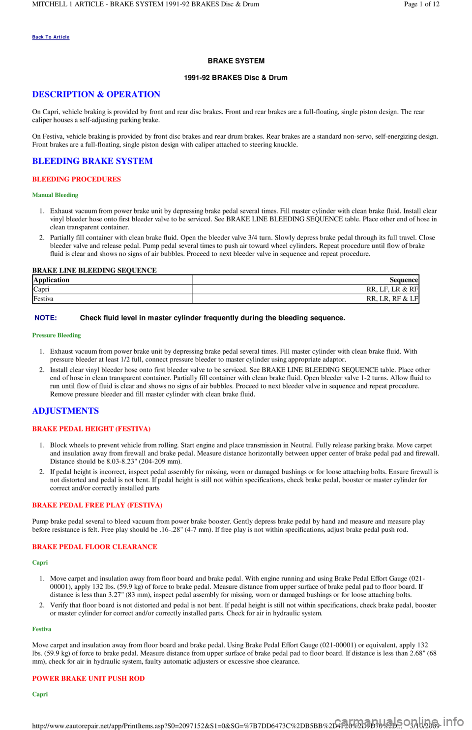
On Capri, vehicle braking is provided by front and rear disc brakes. Front and rear brakes are a full-floating, single piston design. The rear
caliper houses a self-adjusting parking brake.
On Festiva, vehicle braking is provided by front disc brakes and rear drum brakes. Rear brakes are a standard non-servo, self-en e r giz in g d e sign .
Front brakes are a full-floating, single piston design with caliper attached to steering knuckle.
BLEEDING BRAKE SYSTEM
BLEEDING PROCEDURES
Manual Bleeding
1. Exhaust vacuum from power brake unit by depressing brake pedal several times. Fill master cylinder with clean brake fluid. Install clear
vinyl bleeder hose onto first bleeder valve to be serviced. See BRAKE LINE BLEEDING SEQUENCE table. Place other end of hose in
clean transparent container.
2. Partially fill container with clean brake fluid. Open the bleeder valve 3/4 turn. Slowly depress brake pedal through its full travel. Close
bleeder valve and release pedal. Pump pedal several times to push air toward wheel cylinders. Repeat procedure until flow of brake
fluid is clear and shows no signs of air bubbles. Proceed to next bleeder valve in sequence and repeat procedure.
BRAKE LINE BLEEDING SEQUENCE
Pressure Bleeding
1. Exhaust vacuum from power brake unit by depressing brake pedal several times. Fill master cylinder with clean brake fluid. With
pressure bleeder at least 1/2 full, connect pressure bleeder to master cylinder using appropriate adaptor.
2. Install clear vinyl bleeder hose onto first bleeder valve to be serviced. See BRAKE LINE BLEEDING SEQUENCE table. Place other
end of hose in clean transparent container. Partially fill container with clean brake fluid. Open bleeder valve 1-2 turns. Allow fluid to
run until flow of fluid is clear and shows no signs of air bubbles. Proceed to next bleeder valve in sequence and repeat procedure.
Remove pressure bleeder and fill master cylinder with clean brake fluid.
ADJUSTMENTS
BRAKE PEDAL HEIGHT (FESTIVA)
1. Block wheels to prevent vehicle from rolling. Start engine and place transmission in Neutral. Fully release parking brake. Move carpet
and insulation away from firewall and brake pedal. Measure distance horizontally between upper center of brake pedal pad and firewall.
Distance should be 8.03-8.23" (204-209 mm).
2. If pedal height is incorrect, inspect pedal assembly for missing, worn or damaged bushings or for loose attaching bolts. Ensure firewall is
not distorted and pedal is not bent. If pedal height is still not within specifications, check brake pedal, booster or master cylinder for
correct and/or correctly installed parts
BRAKE PEDAL FREE PLAY (FESTIVA)
Pump brake pedal several to bleed vacuum from power brake booster. Gently depress brake pedal by hand and measure and measure play
before resistance is felt. Free play should be .16-.28" (4-7 mm). If free play is not within specifications, adjust brake pedal push rod.
BRAKE PEDAL FLOOR CLEARANCE
Capri
1. Move carpet and insulation away from floor board and brake pedal. With engine running and using Brake Pedal Effort Gauge (021-
00001), apply 132 lbs. (59.9 kg) of force to brake pedal. Measure distance from upper surface of brake pedal pad to floor board. If
distance is less than 3.27" (83 mm), inspect pedal assembly for missing, worn or damaged bushings or for loose attaching bolts.
2. Verify that floor board is not distorted and pedal is not bent. If pedal height is still not within specifications, check brake pedal, booster
or master cylinder for correct and/or correctly installed parts. Check for air in hydraulic system.
Festiva
Move carpet and insulation away from floor board and brake pedal. Using Brake Pedal Effort Gauge (021-00001) or equivalent, apply 132
lbs. (59.9 kg) of force to brake pedal. Measure distance from upper surface of brake pedal pad to floor board. If distance is less than 2.68" (68
mm), check for air in hydraulic system, faulty automatic adjusters or excessive shoe clearance.
POWER BRAKE UNIT PUSH ROD
Capri
ApplicationSequence
CapriRR, LF, LR & RF
FestivaRR, LR, RF & LF
NOTE:Check fluid level in m aster cylinder frequently during the bleeding sequence.
Page 1 of 12 MITCHELL 1 ARTICLE - BRAKE SYSTEM 1991-92 BRAKES Disc & Drum
3/10/2009 http://www.eautorepair.net/app/PrintItems.asp?S0=2097152&S1=0&SG=%7B7DD6473C%2DB5BB%2D4F20%2D9D70%2D
...
Page 40 of 454
Back To Article
AXLE SHAFT S - FRONT
1988-93 Drive Axles - FWD Axle Shafts
DESCRIPTION & OPERATION
Axle shafts transfer power from transaxle to driving wheels. All axle shafts consist of a shaft with a flexible Constant Velocity (CV) joint at
each end. Inner CV joint is coupled to transaxle by splines. Outer CV joint is splined to hub assembly and secured by axle shaft nut.
Three different types of axle shaft CV joints are used: Double Offset Joint (DOJ) or Rzeppa type, Birfield Joint (BJ) and the Tripot Joint (TJ).
CV joint boots protect CV joints by maintaining proper lubrication and preventing contaminants from entering joint. Boots must be replaced
when signs of leakage or cracks are present. Inner CV joint may be disassembled and serviced. Outer CV joint boot may be replaced, but outer
Birfield CV joint must NOT be disassembled. It must be replaced as an assembly, if faulty.
To prevent torsional vibration and torque steer on turbocharged Capri vehicles, an intermediate shaft and conventional axle shaft are used on
the right side. Both shafts are of similar length and are supported by a bearing, which is attached to engine.
CV JOINT IDENTIFICATION
TROUBLE SHOOTING
REMOVAL, DISASSEMBLY, REASSEMBLY & INSTALLATION
FWD AXLE SHAFTS
Removal
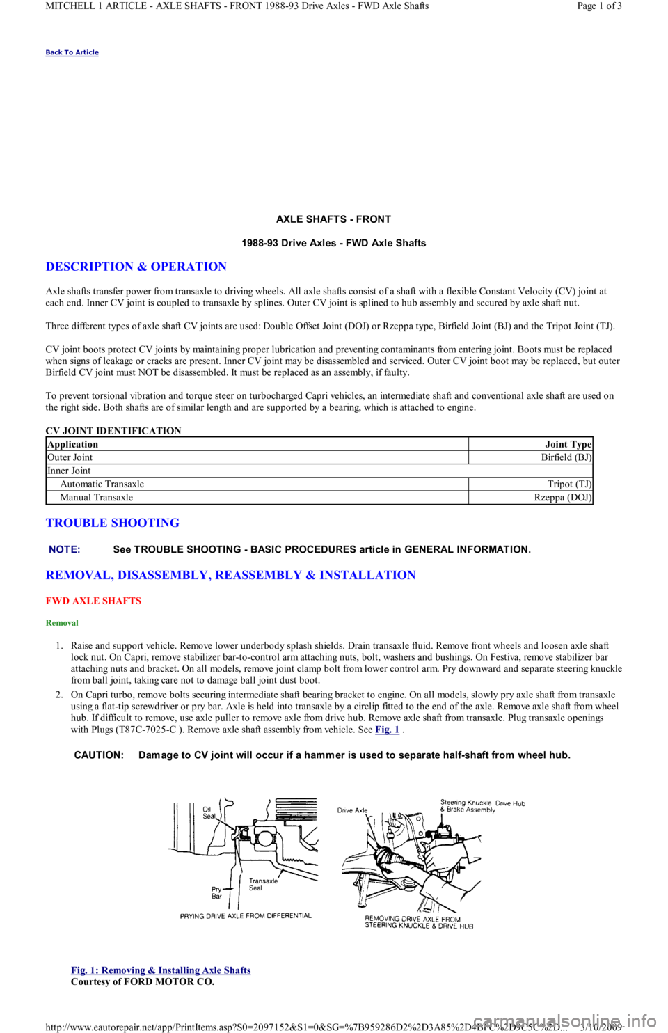
1. Raise and support vehicle. Remove lower underbody splash shields. Drain transaxle fluid. Remove front wheels and loosen axle shaft
lock nut. On Capri, remove stabilizer bar-to-control arm attaching nuts, bolt, washers and bushings. On Festiva, remove stabilizer bar
attaching nuts and bracket. On all models, remove joint clamp bolt from lower control arm. Pry downward and separate steering knuckle
from ball joint, taking care not to damage ball joint dust boot.
2. On Capri turbo, remove bolts securing intermediate shaft bearing bracket to engine. On all models, slowly pry axle shaft from transaxle
using a flat-tip screwdriver or pry bar. Axle is held into transaxle by a circlip fitted to the end of the axle. Remove axle shaft from wheel
hub. If difficult to remove, use axle puller to remove axle from drive hub. Remove axle shaft from transaxle. Plug transaxle openings
with Plugs (T87C-7025-C ). Remove axle shaft assembly from vehicle. See Fig. 1
.
Fig. 1: Removing & Installing Axle Shafts
Courtesy of FORD MOTOR CO.
ApplicationJoint Type
Outer JointBirfield (BJ)
In n er Jo in t
Automatic TransaxleTripot (TJ)
Manual TransaxleRzeppa (DOJ)
NOTE:See TROUBLE SHOOTING - BASIC PROCEDURES article in GENERAL INFORMATION.
CAUTION: Dam age to CV joint will occur if a ham mer is used to separate half-shaft from wheel hub.
Page 1 of 3 MITCHELL 1 ARTICLE - AXLE SHAFTS - FRONT 1988-93 Drive Axles - FWD Axle Shafts
3/10/2009 http://www.eautorepair.net/app/PrintItems.asp?S0=2097152&S1=0&SG=%7B959286D2%2D3A85%2D4BFC%2D9C5C%2D
...
Page 47 of 454
SOLENOIDS & SOLENOID VALVES
SOLENOIDS & SOLENOID VALVES LOCATION
SWITCHES
SWITCHES LOCATION
MISCELLANEOUS
MISCELLANEOUS LOCATION
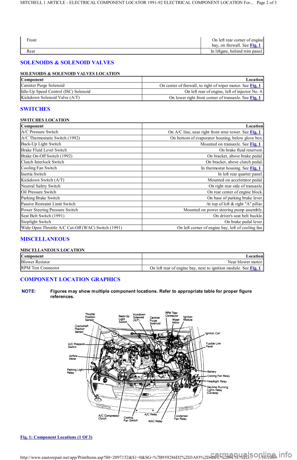
COMPONENT LOCATION GRAPHICS
Fig. 1: Component Locations (1 Of 3)
FrontOn left rear corner of engine
bay, on firewall. See Fig. 1
.
RearIn liftgate, behind trim panel.
ComponentLocation
Canister Purge SolenoidOn center of firewall, to right of wiper motor. See Fig. 1 .
Idle-Up Speed Control (ISC) SolenoidOn left rear of engine, left of injector No. 4.
Kickdown Solenoid Valve (A/T)On lower right front corner of transaxle. See Fig. 1 .
ComponentLocation
A/C Pressure SwitchOn A/C line, near right front strut tower. See Fig. 1 .
A/C Thermostatic Switch (1992)On bottom of evaporator housing, below glove box.
Back-Up Light SwitchMounted on transaxle. See Fig. 1 .
Brake Fluid Level SwitchOn brake fluid reservoir.
Brake On-Off Switch (1992)On bracket, above brake pedal.
Clutch Interlock SwitchOn bracket, above clutch pedal.
Cooling Fan SwitchIn thermostat housing. See Fig. 1 .
Inertia SwitchIn left rear quarter panel.
Kickdown Switch (A/T)Mounted on accelerator pedal.
Neutral Safety SwitchOn right rear side of transaxle.
Oil Pressure SwitchOn rear center of engine block.
Parking Brake SwitchOn base of parking brake lever.
Passive Restraint Limit SwitchAt top of left & right "A" pillar.
Power Steering Pressure SwitchMounted on power steering pump assembly.
Seat Belt Switch (1991)On driver's seat belt buckle.
Stoplight SwitchOn brake pedal lever.
Wide Open Throttle A/C Cut-Off (WAC) Switch (1991)On left corner of engine bay, left of cooling fan.
ComponentLocation
Blower ResistorNear blower motor.
RPM Test ConnectorOn left rear of engine bay, next to ignition module. See Fig. 1 .
NOTE:Figures m ay show m ultiple com ponent locations. Refer to appropriate table for proper figure
references.
Page 2 of 3 MITCHELL 1 ARTICLE - ELECTRICAL COMPONENT LOCATOR 1991-92 ELECTRICAL COMPONENT LOCATION For...
3/10/2009 http://www.eautorepair.net/app/PrintItems.asp?S0=2097152&S1=0&SG=%7B959286D2%2D3A85%2D4BFC%2D9C5C%2D
...
Page 66 of 454
Autolamp Control RelayHeadlight Systems; Daytime Running Lights
Automatic Shutdown (ASD) RelayEngine Performance; Generators & Regulators
Autostick SwitchEngine Performance
Auxiliary Battery RelayGenerators & Regulators
Back-Up LightsBack-Up Lights; Exterior Lights
Barometric (BARO) Pressure SensorEngine Performance
BatteryPower Distribution
Battery Temperature SensorEngine Performance
Body Control ModuleBody Control Computer; Anti-Theft System; Daytime Running
Lights; Engine Performance; Headlight Systems; Warning Systems
Boost Control SolenoidEngine Performance
Boost SensorEngine Performance
Brake Fluid Level SwitchAnalog Instrument Panels
Brake On/Off (BOO) SwitchCruise Control Systems; Engine Performance; Shift Interlock
Systems
Buzzer ModuleWarning Systems
Camshaft Position (CMP) SensorEngine Performance
Central Control ModuleAnti-Theft System
ClockspringAir Bag Restraint System; Cruise Control Systems; Steering
Column Switches
Clutch Pedal Position SwitchStarters
Clutch Start SwitchStarters
Combination MeterAnalog Instrument Panels
Constant Control Relay Module (CCRM)Engine Performance; Electric Cooling Fans
Convenience CenterPower Distribution; Illumination/Interior Lights
Convertible Top MotorPower Convertible Top
Convertible Top SwitchPower Convertible Top
Crankshaft Position (CKP) SensorEngine Performance
Cruise Control ModuleCruise Control Systems
Cruise Control SwitchCruise Control Systems
Condenser Fan Relay(s)Electric Cooling Fans
Data Link Connector (DLC)Engine Performance
Da yt ime R u n n in g Ligh t s M o d u l eDaytime Running Lights; Exterior Lights
Defogger RelayRear Window Defogger
Diagnostic Energy Reserve Module (DERM)Air Bag Restraint System
Discriminating Sensor (Air Bag)Air Bag Restraint System
DistributorEngine Performance
Door Lock ActuatorsPower Door Locks; Remote Keyless Entry
Door Lock Relay(s)Power Door Locks
Electrochromic MirrorPower Mirrors
Electronic Level Control (ELC) Height SensorElectronic Suspension
Electronic Level Control (ELC) ModuleElectronic Suspension
Engine Coolant Temperature (ECT) Sending UnitAnalog Instrument Panels
Engine Coolant Temperature (ECT) SensorEngine Performance
Engine Control ModuleEngine Performance; Generators & Regulators; Starters
ETACS ECUWarning Systems; Power Windows; Remote Keyless Entry
Evaporative (EVAP) Emissions CanisterEngine Performance
EVAP Canister Purge SolenoidEngine Performance
EVAP Canister Vent SolenoidEngine Performance
Exhaust Gas Recirculation (EGR) ValveEngine Performance
Fuel Tank Vacuum SensorEngine Performance
F o g Ligh t sHeadlight Systems; Daytime Running Lights
F o g Ligh t R e l a yHeadlight Systems; Daytime Running Lights
Fuel Door Release SolenoidPower Fuel Door Release
Fuel Gauge Sending UnitAnalog Instrument Panels
Fuel InjectorsEngine Performance
Fuel PumpEngine Performance
Fuel Pump RelayEngine Performance; Power Distribution
Fuse/Relay BlockPower Distribution
Fusible LinksPower Distribution; Generators & Regulators; Starters
GeneratorGenerators & Regulators; Engine Performance; Power Distribution
Generic Electronic Module (GEM)Body Control Modules; Electronic Suspension
Glow Plug RelayEngine Performance
Glow PlugsEngine Performance
GroundsGround Distribution
Headlight Door ModuleHeadlight Doors
Headlight RelayHeadlight Systems; Daytime Running Lights
HeadlightsHeadlight Systems; Daytime Running Lights
Heated Oxygen Sensor(s) (HO2S)Engine Performance
Heated Windshield Control ModuleHeated Windshields
Page 4 of 6 MITCHELL 1 ARTICLE - GENERAL INFORMATION Using Mitchell1's Wiring Diagrams
3/10/2009 http://www.eautorepair.net/app/PrintItems.asp?S0=2097152&S1=0&SG=%7B959286D2%2D3A85%2D4BFC%2D9C5C%2D
...
Page 102 of 454
levels to proper level.
Removal (1.6L & 1.6L Turbo)
1. Relieve fuel pressure and discharge air conditioning system (if equipped). See FUEL PRESSURE RELEASE under REMOVAL &
INSTALLATION. Disconnect and remove battery, battery tray and battery tray support bracket.
2. Release wiring harness retaining straps from battery support tray. Disconnect windshield washer supply hose between fluid reservoir and
hood. Mark hinge locations and remove hood.
3. Disconnect intake air tube and wiring to ignition coil and vane airflow meter. Remove air cleaner/vane airflow meter assembly. Remove
air cleaner assembly support brackets. Disconnect intercooler hoses from turbocharger (if equipped).
4. Drain engine coolant and remove radiator. Disconnect accelerator cable, and remove retaining bracket from cam cover. Position cable to
one side.
5. Disconnect and plug fuel lines at fuel filter and pressure regulator. Disconnect power brake booster manifold vacuum hose from
manifold. Disconnect heater hoses at heater core tubes. Label and remove vacuum hoses located at throttle body.
6. For manual transaxle turbocharged vehicles, disconnect clutch cable and remove support bracket and cable from transmission. On non-
turbo vehicles, disconnect clutch slave hydraulic line. For automatic transaxle, remove transaxle cooler lines.
7. Disconnect starter wiring at starter. Remove harness from locating strap on bracket. Disconnect alternator wiring. Disconnect wiring
from engine coolant sensors located on rear of engine block. Remove ground connection at bracket on thermostat cover. Disconnect O2
sensor wire, main wiring harness connector, TPS connector (turbocharged only), knock sensor connector, distributor wiring and
transaxle wiring. Disconnect ground wire and strap at front of engine, and reinstall lifting eye.
8. Remove engine oil dipstick and retaining clip. Remove power steering pump from mounting bracket. Remove power steering pump
mounting bracket. With hoses attached, position pump aside. Remove upper air conditioning compressor retaining bolts (if equipped).
9. Raise vehicle on hoist. Drain engine oil and cooling system. On vehicles with air conditioning, remove lower air conditioning
compressor mounting bolts, and position compressor out of way.
10. Remove front wheels and tires. Remove front ball joints-to-ste e r in g kn u c kl e s r e t a in in g b o l t s. R e mo ve sp l a sh gu a r d s. Dr a in t ransmission
oil and remove half shafts from differential. Remove front exhaust pipe bracket located on lower side of engine. Disconnect front
exhaust pipe from exhaust manifold, or turbocharger (if equipped).
11. Remove frame support bar-to-engine support bolt. Loosen right control arm bolt and, pivot support bar downward. Disengage rubber
exhaust hangers located directly behind catalytic converter. Allow exhaust system to hang down 6 inches, and support system with
mechanic's wire. Unbolt shift linkage and stabilizer bar at transaxle. Remove nuts from front and rear engine mounts, and lower vehicle.
12. Attach chains onto lift eyes at ends of cylinder head, and support engine with hoist. Remove RH engine mount through bolt. Raise
engine off mounts and slightly pivot engine/transaxle assembly. Disconnect oil pressure sensor and route starter/alternator wiring
harness from engine. Carefully lift engine/transaxle assembly, turn assembly while raising to clear brake master cylinder, shift linkage
universal joint, radiator support and air conditioning lines (if equipped).
13. Remove intake manifold support bracket. Remove gusset plate(s) (if equipped). Remove starter. Remove transaxle-to-engine retaining
bolts. Identify bolts to ensure correct installation. Separate transaxle from engine. On manual transaxle, remove pressure plate, clutch
disc and flywheel. On automatic transaxle, remove flexplate.
Installation (1.6L & 1.6L Turbo)
1. Install transaxle to engine in reverse order of removal. Attach hoist to engine/transaxle assembly and position assembly in vehicle.
Before engine contacts mounts, route starter, alternator and oil pressure sensor wiring, and connect oil pressure sensor. Lower engine
until front mount seats on crossmember. Install through bolt on RH engine mount. DO NOT tighten bolt.
2. Remove hoist. Raise vehicle and support with jackstands. Align rear engine mount to crossmember, and install retaining nuts to front
and rear engine mounts. Tighten nuts to specification. See TORQUE SPECIFICATIONS
table at end of article.
3. On manual transaxles, connect shift coupling and stabilizer. Tighten to specification. On automatic transaxles, connect shift linkage and
oil cooler lines. Tighten linkage retaining bolt, shift cable pivot and oil cooler hose clamps to specification. Connect front exhaust pipe
to manifold (or turbocharger). Install exhaust pipe to support bracket. Tighten bolts to specification. Tighten manifold (or turbocharger)
to specification. Attach rubber exhaust hangers. Position cross brace. Tighten retaining nut and bolt and right control arm front bolt.
4. Install drive axles. Install ball joint retaining bolts and tighten to specification. Mount A/C Compressor to engine (if equipped). Tighten
lower retaining bolts to specification. Install splash guards. Install tire and wheel assemblies. Tighten retaining nuts to specification.
5. Lower vehicle. Install upper A/C compressor retaining bolts (if equipped). Tighten bolts to specification. Tighten RH engine mo u n t
through bolt to specification. Connect alternator wiring.
6. Position power steering pump bracket on stud. Lower pump into engine compartment. Install power steering pump bracket retaining
bolts and nut. Tighten to specification. Install power steering pump and belt. Tighten adjustment nut and pivot bolt to specification.
7. Install engine oil dipstick and retaining clip. Install ground strap and ground wire to cylinder head. Install clutch cable (if equipped).
Connect clutch hydraulic line if equipped with manual transaxle or naturally aspirated. Connect transmission electrical connectors.
Connect fuel lines to fuel filter and pressure regulator. Install intake air tube to throttle body.
8. Install intercooler hoses on turbocharged models. Install air cleaner assembly brackets. Install air cleaner assembly with airflow meter
attached. Install intake air tube. Install coil and airflow meter connectors. Connect coolant crankcase and air bypass hoses. Install
vacuum hoses as noted in disassembly.
9. Connect accelerator cable. Install retaining bracket. Install power brake booster hose. Remove speedometer cable from transaxle. Fill
transaxle to specification. See CAPACITIES in SERVICE & ADJUSTMENT SPECIFICATIONS article. Install speedometer cable.
Connect speedometer cable connector. Fill engine oil to capacity.
10. Install radiator/fan assembly. Tighten bracket retaining bolts to specification. Connect coolant hoses and fan electrical connector. Fill
coolant to specification.
11. Install hood and connect washer hose. Install battery tray support, battery tray, battery and battery hold-down. Connect battery
terminal. Evacuate and charge air conditioning system (if equipped). Road test vehicle and inspect for leaks.
INTAKE MANIFOLD
Removal (1.3L)
CAUT ION: DO NOT allow com pressor to hang by hoses. T ie up com pressor with m echanic's wire.
Page 2 of 19 MITCHELL 1 ARTICLE - ENGINE OVERHAUL 1991-92 FORD MOTOR CO. ENGINES 1.3L & 1.6L 4-Cylinder
3/10/2009 http://www.eautorepair.net/app/PrintItems.asp?S0=2097152&S1=0&SG=%7B959286D2%2D3A85%2D4BFC%2D9C5C%2D
...
Page 103 of 454
Disconnect negative battery cable. Drain cooling system. Remove air cleaner. Remove intake manifold bracket. Disconnect throttle cable.
Mark and disconnect vacuum hoses, fuel hoses and wiring. Remove intake manifold bolts. Remove intake manifold and gasket.
Installation (1.3L)
Clean all gasket mating surfaces. Ensure surface is free of burrs, scratches and cracks. Replace all gaskets. Position gasket and manifold to
cylinder head. Install bolts and tighten to specification. To complete installation, reverse removal procedure.
Removal (1.6L)
1. Disconnect negative battery terminal. Relieve fuel pressure. See FUEL PRESSURE RELEASE under REMOVAL &
INSTALLATION. Drain cooling system. Disconnect intercooler tube and/or air intake tube. Disconnect air by-pass hoses. Disconnect
main engine harness electrical connection and TPS connector. Disconnect vacuum hoses from throttle body.
2. Disconnect fuel lines from fuel filter and pressure regulator. Disconnect throttle cable. Disconnect hoses from By-pass Air Control valve
( B AC ) . R e mo ve B AC va l ve r e t a in in g n u t a n d b o l t . R e mo ve in t a ke manifold retaining nuts and bolts from support bracket and cylinder
head. Remove intake manifold and throttle body assembly.
Installation (1.6L)
1. Install new intake manifold gasket, ensuring coolant passage openings align with openings in cylinder head and manifold. Install intake
manifold. Tighten retaining nut and bolts and support bracket bolts to specification. See TORQUE SPECIFICATIONS
table at end of
article.
2. Install BAC valve and connect air hoses. Connect throttle cable. Connect fuel lines to fuel filters and pressure regulator. Connect main
engine harness connector and TPS connector. Connect vacuum lines to throttle body. Install intake air tube. Connect intercooler tube
and/or intake air tube. Connect air by-pass hoses. Fill cooling system. Connect negative battery terminal. Start engine and check for
fluid leaks and correct operation.
EXHAUST MANIFOLD
Removal (1.3L)
1. Raise vehicle. Remove catalytic converter inlet pipe at exhaust manifold. Remove pulse air tube nuts at inlet pipe. Remove inlet pipe
support bracket bolts. Lower vehicle. Remove air intake duct. Remove exhaust manifold heat shroud bolts and remove shroud.
2. Disconnect oxygen sensor connector. Remove exhaust manifold nuts and remove exhaust manifold. Remove gasket from inlet pipe and
cylinder head.
Installation
Position new gasket on cylinder head and inlet pipe. Install exhaust manifold and nuts. Tighten nuts to specification. See, at end of article,
TORQUE SPECIFICATIONS
table. To complete installation, reverse removal procedure. Tighten all bolts and nuts to specification.
Removal (1.6L Non-Turbo)
Remove intake air tube. Remove front exhaust pipe to exhaust manifold retaining nuts. Remove exhaust support bracket (if equipped). Remove
heat shield. Disconnect O2 sensor electrical connector. Remove exhaust manifold.
Installation (1.6L Non-Turbo)
Install exhaust manifold gaskets. Install heavier gasket first. Install exhaust manifold and tighten retaining nuts to specification. See TORQUE
SPECIFICATIONS table at end of article. Connect O2 sensor electrical connector. Install manifold heat shield. Install intake air tube.
Connect front exhaust pipe to intake manifold and tighten retaining nuts to specification. Install exhaust support bracket, if removed, and
tighten engine mount bolt to specification. Start engine and check for leaks.
Removal (1.6L Turbo)
1. Disconnect negative battery cable. Drain cooling system. Remove throttle body air intake tube. Disconnect intercooler hose from
turbocharger assembly and position both intercooler hoses out of the way. Remove O2 sensor connector from its retaining clip, and
disconnect O2 sensor. Remove lower heat shield and then upper heat shield. Remove turbocharger side heat shield.
2. Remove power steering pump (leave hoses attached) and lay aside. Disconnect lower radiator hose from water pump. Position power
steering pump to access mounting bracket retaining bolts and nut. Remove both bolts and one nut, and remove bracket from engine.
Remove 2 screws retaining air cleaner duct tube, loosen clamp at turbocharger and position duct tube out of the way. Disconnect
coolant return hose at turbocharger. Remove bolt and brass sealing washers from oil supply line at engine block.
3. Raise vehicle. Remove retaining nuts and washers from exhaust pipe flange. Remove 2 bolts retaining exhaust hangers to engine block.
Slide off two rubber exhaust hangers at catalytic converter. Pull exhaust pipe downward and to LH side of vehicle. Disconnect oil return
hose at turbocharger. Disconnect coolant return hose at turbocharger. Remove 2 retaining bolts from turbocharger support bracket.
Remove 2 bolts retaining coolant by-pass tube outlet to water pump. Lower vehicle.
4. Loosen retaining clamp bolt on coolant by-pass tube at rear of cylinder head. Remove 11 retaining nuts from exhaust manifold. Pull
coolant by-pass tube bracket from exhaust stud, and position tube out of way. Grasp manifold, pull off studs and move assembly slightly
to RH side of engine compartment to clear cooling fan, and remove assembly from vehicle.
5. Working on bench, remove 4 nuts retaining turbocharger to exhaust manifold, separate assembly and discard gasket.
Installation (1.6L Turbo)
NOTE:Feed O2 sensor wire and guide through upper heat shield.
NOTE:When reinstalling turbocharger, thoroughly rem ove all gaskets and sealant. Use new gaskets. Add .85
oz. (25 cc) of engine oil in the oil passage of the turbocharger.
Page 3 of 19 MITCHELL 1 ARTICLE - ENGINE OVERHAUL 1991-92 FORD MOTOR CO. ENGINES 1.3L & 1.6L 4-Cylinder
3/10/2009 http://www.eautorepair.net/app/PrintItems.asp?S0=2097152&S1=0&SG=%7B959286D2%2D3A85%2D4BFC%2D9C5C%2D
...
Page 104 of 454
1. Position new gasket on exhaust manifold, and install turbocharger onto studs. Install 4 retaining nuts and tighten to specification. See
TORQUE SPECIFICATIONS
table at end of article.
2. Remove oil supply line from turbocharger. Position new (2-piece) exhaust gasket on cylinder head with heavy gasket installed first .
Carefully position turbocharger assembly in engine compartment and slide exhaust manifold on studs. Position heater tube bracket onto
exhaust stud. Install 11 retaining nuts onto exhaust manifold and tighten to specification. See TORQUE SPECIFICATIONS
table at
end of article. Tighten heater tube clamp bolt securely.
3. Raise vehicle. Position new gasket and install 2 retaining bolts on heater tube outlet. Install 2 retaining bolts into turbocharger support
bracket and tighten bolts to specification.
4. Connect coolant return hose. Connect oil return hose and secure with clamp. Position exhaust pipe onto turbocharger, and start nuts
and washers. Install 2 retaining bolts on exhaust hanger at engine. Slide on 2 rubber exhaust hangers at catalytic converter. Tighten
exhaust pipe retaining nuts to specification. Lower vehicle.
5. Install retaining bolt and brass washers on oil supply line, carefully position oil line into vehicle and hand-start bolt into engine block.
Connect and finger tighten oil line to turbocharger. Tighten oil line bolt and oil supply line on turbocharger to specification.
6. Connect coolant supply hose. Position air cleaner duct tube on turbocharger and tighten clamp. Install 2 screws retaining air cleaner
duct tube. Position power steering pump bracket on engine, and install 2 retaining bolts and one retaining nut. Tighten to specification.
Position power steering pump on mounting bracket, and install though bolt and adjuster. Connect lower radiator hose. Install power
steering belt. Position upper heat shield and install 2 retaining bolts finger tight.
7. Position lower heat shield and install three retaining bolts finger tight. Tighten all heat shield bolts to specification. Connect O2 sensor
and install connector into its retaining clip. See TORQUE SPECIFICATIONS
table at end of article. Position intercooler hose on
turbocharger and secure with clamp. Install throttle body air intake tube. Connect negative battery cable. Refill cooling system.
CYLINDER HEAD
Removal (1.3L)
1. Disconnect battery ground cable. Mark and disconnect fuel lines at fuel pump. Remove accessory belts, water pump pulley, crankshaft
pulley, timing belt covers, timing belt tensioner, timing belt, valve cover and exhaust and intake manifolds. Drain cooling system.
2. Mark and remove electrical connectors and vacuum hoses. Remove spark plug wires from spark plugs, and remove spark plugs. Remove
distributor cap. Disconnect vacuum hoses and distributor wiring.
3. Index distributor-to-mount position and remove hold-down bolt. Remove distributor assembly. Remove engine ground strap. Remove
front and rear engine lifting hooks. Remove upper radiator hose, by-pass hose and bracket.
4. Remove bolts retaining rocker arm shaft. Remove rocker arm assemblies. Remove cylinder head bolts. Remove head and gasket.
Inspection (1.3L)
1. Thoroughly clean and check gasket mating surface of cylinder head and block. Check cylinder for cracks, nicks, burrs or damage. Using
a straightedge and feeler gauge, check warpage over entire gasket area. Ensure cylinder head and/or block warpage does not
exceed .006" (.15 mm).
2. If warpage exceeds .006" (.15 mm), machine cylinder head and/or block gasket surface. Maximum machining allowed is .008" (.20 mm).
If more machining is required, replace block and/or cylinder head.
Installation (1.3L)
1. Place new head gasket properly on block. Carefully place cylinder head in position on block. Install head bolts. Tighten bolts in
sequence and in 2 steps. See Fig. 1
.
2. While tightening rocker arm shaft, slide shaft springs away from retaining bolt to prevent pinching springs. Tighten rocker arm shaft bolts
in sequence and to specification. See Fig. 5
. To complete installation, reverse removal procedure. Tighten all bolts/nuts to
specification. Fill all fluids to proper levels. NOTE:T urbocharger-to-exhaust m anifold m ounting nuts are of special quality. Ensure correct nuts are
used.
NOTE:Ensure one brass washer is positioned on each side of oil line fitting.
NOTE:Feed O2 sensor wire through upper heat shield. Install wire retainer under LH bolt.
NOTE:If turbocharger was replaced: Disconnect ignition coil, crank engine for 20 seconds, connect ignition
coil, start engine and run at idle for 30 seconds and check for leaks.
NOTE:If original tim ing belt is being reused, m ark direction of rotation for installation reference.
Page 4 of 19 MITCHELL 1 ARTICLE - ENGINE OVERHAUL 1991-92 FORD MOTOR CO. ENGINES 1.3L & 1.6L 4-Cylinder
3/10/2009 http://www.eautorepair.net/app/PrintItems.asp?S0=2097152&S1=0&SG=%7B959286D2%2D3A85%2D4BFC%2D9C5C%2D
...
Page 244 of 454
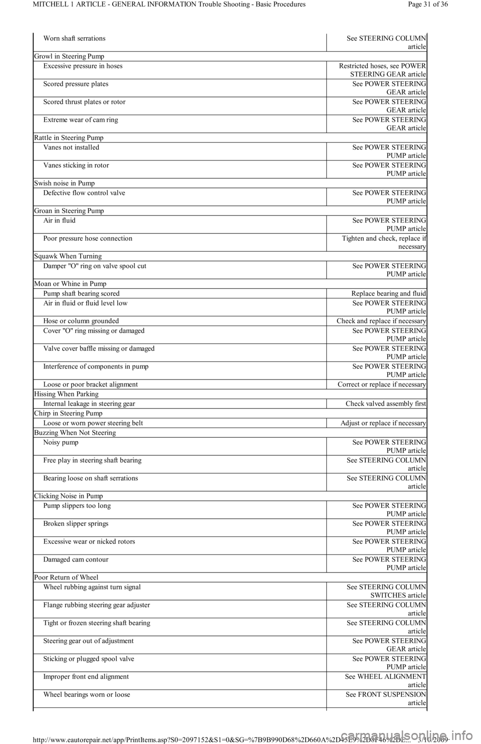
Worn shaft serrationsSee STEERING COLUMN
article
Growl in Steering Pump
Excessive pressure in hosesRestricted hoses, see POWER
STEERING GEAR article
Scored pressure platesSee POWER STEERING
GEAR article
Scored thrust plates or rotorSee POWER STEERING
GEAR article
Extreme wear of cam ringSee POWER STEERING
GEAR article
Rattle in Steering Pump
Vanes not installedSee POWER STEERING
PUMP article
Vanes sticking in rotorSee POWER STEERING
PUMP article
Swish noise in Pump
Defective flow control valveSee POWER STEERING
PUMP article
Groan in Steering Pump
Air in fluidSee POWER STEERING
PUMP article
Poor pressure hose connectionTighten and check, replace if
necessary
Squawk When Turning
Damper "O" ring on valve spool cutSee POWER STEERING
PUMP article
Moan or Whine in Pump
Pump shaft bearing scoredReplace bearing and fluid
Air in fluid or fluid level lowSee POWER STEERING
PUMP article
Hose or column groundedCheck and replace if necessary
Cover "O" ring missing or damagedSee POWER STEERING
PUMP article
Valve cover baffle missing or damagedSee POWER STEERING
PUMP article
Interference of components in pumpSee POWER STEERING
PUMP article
Loose or poor bracket alignmentCorrect or replace if necessary
Hissing When Parking
Internal leakage in steering gearCheck valved assembly first
Chirp in Steering Pump
Loose or worn power steering beltAdjust or replace if necessary
Buzzing When Not Steering
Noisy pumpSee POWER STEERING
PUMP article
Free play in steering shaft bearingSee STEERING COLUMN
article
Bearing loose on shaft serrationsSee STEERING COLUMN
article
Clicking Noise in Pump
Pump slippers too longSee POWER STEERING
PUMP article
Broken slipper springsSee POWER STEERING
PUMP article
Excessive wear or nicked rotorsSee POWER STEERING
PUMP article
Damaged cam contourSee POWER STEERING
PUMP article
Poor Return of Wheel
Wheel rubbing against turn signalSee STEERING COLUMN
SWITCHES article
Flange rubbing steering gear adjusterSee STEERING COLUMN
article
Tight or frozen steering shaft bearingSee STEERING COLUMN
article
Steering gear out of adjustmentSee POWER STEERING
GEAR article
Sticking or plugged spool valveSee POWER STEERING
PUMP article
Improper front end alignmentSee WHEEL ALIGNMENT
article
Wheel bearings worn or looseSee FRONT SUSPENSION
article
Page 31 of 36 MITCHELL 1 ARTICLE - GENERAL INFORMATION Trouble Shooting - Basic Procedures
3/10/2009 http://www.eautorepair.net/app/PrintItems.asp?S0=2097152&S1=0&SG=%7B9B990D68%2D660A%2D45E9%2D8F46%2DE
...
Page 245 of 454
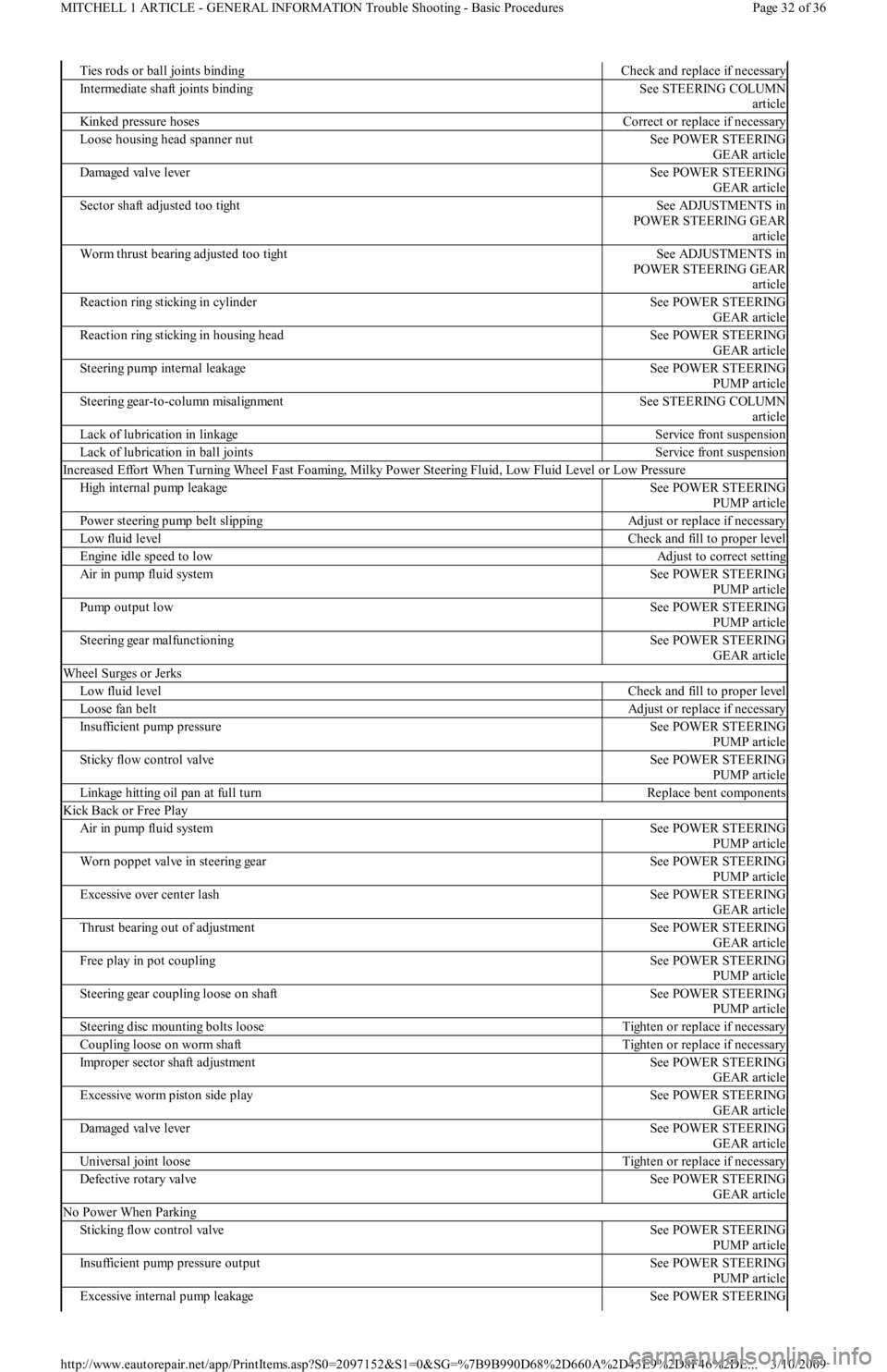
Ties rods or ball joints bindingCheck and replace if necessary
Intermediate shaft joints bindingSee STEERING COLUMN
article
Kinked pressure hosesCorrect or replace if necessary
Loose housing head spanner nutSee POWER STEERING
GEAR article
Damaged valve leverSee POWER STEERING
GEAR article
Sector shaft adjusted too tightSee ADJUSTMENTS in
POWER STEERING GEAR
article
Worm thrust bearing adjusted too tightSee ADJUSTMENTS in
POWER STEERING GEAR
article
Reaction ring sticking in cylinderSee POWER STEERING
GEAR article
Reaction ring sticking in housing headSee POWER STEERING
GEAR article
Steering pump internal leakageSee POWER STEERING
PUMP article
Steering gear-to-column misalignmentSee STEERING COLUMN
article
Lack of lubrication in linkageService front suspension
Lack of lubrication in ball jointsService front suspension
Increased Effort When Turning Wheel Fast Foaming, Milky Power Steering Fluid, Low Fluid Level or Low Pressure
High internal pump leakageSee POWER STEERING
PUMP article
Power steering pump belt slippingAdjust or replace if necessary
Low fluid levelCheck and fill to proper level
Engine idle speed to lowAdjust to correct setting
Air in pump fluid systemSee POWER STEERING
PUMP article
Pump output lowSee POWER STEERING
PUMP article
Steering gear malfunctioningSee POWER STEERING
GEAR article
Wheel Surges or Jerks
Low fluid levelCheck and fill to proper level
Loose fan beltAdjust or replace if necessary
Insufficient pump pressureSee POWER STEERING
PUMP article
Sticky flow control valveSee POWER STEERING
PUMP article
Linkage hitting oil pan at full turnReplace bent components
Kick Back or Free Play
Air in pump fluid systemSee POWER STEERING
PUMP article
Worn poppet valve in steering gearSee POWER STEERING
PUMP article
Excessive over center lashSee POWER STEERING
GEAR article
Thrust bearing out of adjustmentSee POWER STEERING
GEAR article
Free play in pot couplingSee POWER STEERING
PUMP article
Steering gear coupling loose on shaftSee POWER STEERING
PUMP article
Steering disc mounting bolts looseTighten or replace if necessary
Coupling loose on worm shaftTighten or replace if necessary
Improper sector shaft adjustmentSee POWER STEERING
GEAR article
Excessive worm piston side playSee POWER STEERING
GEAR article
Damaged valve leverSee POWER STEERING
GEAR article
Universal joint looseTighten or replace if necessary
Defective rotary valveSee POWER STEERING
GEAR article
No Power When Parking
Sticking flow control valveSee POWER STEERING
PUMP article
Insufficient pump pressure outputSee POWER STEERING
PUMP article
Excessive internal pump leakageSee POWER STEERING
Page 32 of 36 MITCHELL 1 ARTICLE - GENERAL INFORMATION Trouble Shooting - Basic Procedures
3/10/2009 http://www.eautorepair.net/app/PrintItems.asp?S0=2097152&S1=0&SG=%7B9B990D68%2D660A%2D45E9%2D8F46%2DE
...
Page 246 of 454
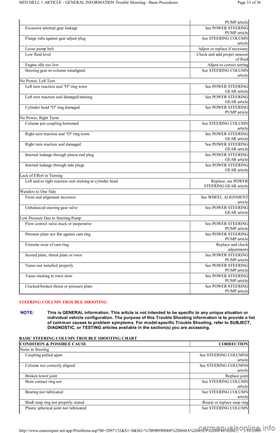
STEERING COLUMN TROUBLE SHOOTING
BASIC STEERING COLUMN TROUBLE SHOOTING CHART
PUMP article
Excessive internal gear leakageSee POWER STEERING
PUMP article
Flange rubs against gear adjust plugSee STEERING COLUMN
article
Loose pump beltAdjust or replace if necessary
Low fluid levelCheck and add proper amount
of fluid
Engine idle too lowAdjust to correct setting
Steering gear-to-column misalignedSee STEERING COLUMN
article
No Power, Left Turn
Left turn reaction seal "O" ring wornSee POWER STEERING
GEAR article
Left turn reaction seal damaged/missingSee POWER STEERING
GEAR article
Cylinder head "O" ring damagedSee POWER STEERING
PUMP article
No Power, Right Turns
Column pot coupling bottomedSee STEERING COLUMN
article
Right turn reaction seal "O" ring wornSee POWER STEERING
GEAR article
Right turn reaction seal damagedSee POWER STEERING
GEAR article
Internal leakage through piston end plugSee POWER STEERING
GEAR article
Internal leakage through side plugsSee POWER STEERING
GEAR article
Lack of Effort in Turning
Left and/or right reaction seal sticking in cylinder headReplace, see POWER
STEERING GEAR article
Wanders to One Side
Front end alignment incorrectSee WHEEL ALIGNMENT
article
Unbalanced steering gear valveSee POWER STEERING
GEAR article
Low Pressure Due to Steering Pump
Flow control valve stuck or inoperativeSee POWER STEERING
PUMP article
Pressure plate not flat against cam ringSee POWER STEERING
PUMP article
Extreme wear of cam ringReplace and check
adjustments
Scored plate, thrust plate or rotorSee POWER STEERING
PUMP article
Vanes not installed properlySee POWER STEERING
PUMP article
Vanes sticking in rotor slotsSee POWER STEERING
PUMP article
Cracked/broken thrust or pressure plateSee POWER STEERING
PUMP article
NOTE:This is GENERAL inform ation. This article is not intended to be specific to any unique situation or
individual vehicle configuration. T he purpose of this T rouble Shooting inform ation is to provide a list
of com m on causes to problem sym ptom s. For m odel-specific T rouble Shooting, refer to SUBJECT ,
DIAGNOST IC, or T EST ING articles available in the section(s) you are accessing.
CONDITION & POSSIBLE CAUSECORRECTION
Noise in Steering
Coupling pulled apartSee STEERING COLUMNS
article
Column not correctly alignedSee STEERING COLUMNS
article
Broken lower jointReplace joint
Horn contact ring notSee STEERING COLUMN
article
Bearing not lubricatedSee STEERING COLUMN
article
Shaft snap ring not properly seatedReseat or replace snap ring
Plastic spherical joint not lubricatedSee STEERING COLUMN
Page 33 of 36 MITCHELL 1 ARTICLE - GENERAL INFORMATION Trouble Shooting - Basic Procedures
3/10/2009 http://www.eautorepair.net/app/PrintItems.asp?S0=2097152&S1=0&SG=%7B9B990D68%2D660A%2D45E9%2D8F46%2DE
...