fuel filter FORD FIESTA 1989 Service Service Manual
[x] Cancel search | Manufacturer: FORD, Model Year: 1989, Model line: FIESTA, Model: FORD FIESTA 1989Pages: 296, PDF Size: 10.65 MB
Page 153 of 296
into the engine induction system and thence
into the combustion chambers. This
arrangement eliminates any fuel mixture
control problems. The operating principles for
the system used on the Endura-E engine are
basically the same as just described with
revisions to the component locations and
hose arrangement.On CVH and PTE engines, a closed-circuit
type crankcase ventilation system is used, the
function of which is basically the same as that
described for the HCS engine type, but the
breather hose connects directly to the rocker
cover. The oil filler cap incorporates a
separate filter in certain applications. On Zetec engines, the crankcase ventilation
system main components are the oil
separator mounted on the front (radiator) side
of the cylinder block/crankcase, and the
Positive Crankcase Ventilation (PCV) valve set
in a rubber grommet in the separator’s left-
hand upper end. The associated pipework
consists of a crankcase breather pipe and two
flexible hoses connecting the PCV valve to a
union on the left-hand end of the inlet
manifold, and a crankcase breather hose
connecting the cylinder head cover to the air
cleaner assembly. A small foam filter in the air
cleaner prevents dirt from being drawn
directly into the engine.
Evaporative emissions control system
This system is fitted to minimise the escape
of unburned hydrocarbons into the
atmosphere. Fuel evaporative emissions
control systems are limited on vehicles
meeting earlier emissions regulations;
carburettor float chambers are vented
internally, whilst fuel tanks vent to atmosphere
through a combined roll-over/anti-trickle-fill
valve. On vehicles meeting the more stringent
emissions regulations, the fuel tank filler cap
is sealed, and a charcoal canister is used to
collect and store petrol vapours generated in
the tank when the vehicle is parked. When the
engine is running, the vapours are cleared
from the canister (under the control of the
EEC IV engine management module via the
canister-purge solenoid valve) into the inlet
tract, to be burned by the engine during
normal combustion. To ensure that the engine runs correctly
when it is cold and/or idling, and to protect
the catalytic converter from the effects of an
over-rich mixture, the canister-purge solenoid
valve is not opened by the EEC IV module
until the engine is fully warmed-up and
running under part-load; the solenoid valve is
then switched on and off, to allow the stored
vapour to pass into the inlet tract.
Pulse-air system
This system consists of the pulse-air
solenoid valve, the pulse-air valve itself, the
delivery tubing, a pulse-air filter, and on some
models, a check valve. The system injects
filtered air directly into the exhaust ports,
using the pressure variations in the exhaust
gases to draw air through from the filter housing; air will flow into the exhaust only
when its pressure is below atmospheric. The
pulse-air valve can allow gases to flow only
one way, so there is no risk of hot exhaust
gases flowing back into the filter.
The system’s primary function is raise
exhaust gas temperatures on start-up, thus
reducing the amount of time taken for the
catalytic converter to reach operating
temperature. Until this happens, the system
reduces emissions of unburned hydrocarbon
particles (HC) and carbon monoxide (CO) by
ensuring that a considerable proportion of
these substances remaining in the exhaust
gases after combustion are burned up, either
in the manifold itself or in the catalytic
converter.
To ensure that the system does not upset
the smooth running of the engine under
normal driving conditions, it is linked by the
pulse-air solenoid valve to the EEC IV module,
so that it only functions during engine warm-
up, when the oxygen sensor is not influencing
the fuel/air mixture ratio.
Catalytic converter
Catalytic converters have been introduced
progressively on all models in the range, to
meet the various emissions regulations.
The catalytic converter is located in the
exhaust system, and operates in conjunction
with an exhaust gas oxygen sensor to reduce
exhaust gas emissions. The catalytic
converter uses precious metals (platinum and
palladium or rhodium) as catalysts to speed
up the reaction between the pollutants and
the oxygen in the vehicle’s exhaust gases, CO
and HC being oxidised to form H
2O and CO2and (in the three-way type of catalytic
converter) NO
xbeing reduced to N2. Note :
The catalytic converter is not a filter in the
physical sense; its function is to promote a
chemical reaction, but it is not itself affected
by that reaction. The converter consists of an element (or
“substrate”) of ceramic honeycomb, coated
with a combination of precious metals in such
a way as to produce a vast surface area over
which the exhaust gases must flow; the whole
being mounted in a stainless-steel box. A
simple “oxidation” (or “two-way”) catalytic
converter can deal with CO and HC only,
while a “reduction” (or “three-way”) catalytic
converter can deal with CO, HC and NO
x.
Three-way catalytic converters are further
sub-divided into “open-loop” (or
“unregulated”) converters, which can remove
50 to 70% of pollutants and “closed-loop”
(also known as “controlled” or “regulated”)
converters, which can remove over 90% of
pollutants.
In order for a closed-loop catalytic
converter to operate effectively, the air/fuel
mixture must be very accurately controlled,
and this is achieved by measuring the oxygen
content of the exhaust gas. The oxygen
sensor transmits information on the exhaust
gas oxygen content to the EEC IV engine management module, which adjusts the
air/fuel mixture strength accordingly.
The sensor has a built-in heating element
which is controlled by the EEC IV module, in
order to bring the sensor’s tip to an efficient
operating temperature as rapidly as possible.
The sensor’s tip is sensitive to oxygen, and
sends the module a varying voltage
depending on the amount of oxygen in the
exhaust gases; if the inlet air/fuel mixture is
too rich, the sensor sends a high-voltage
signal. The voltage falls as the mixture
weakens. Peak conversion efficiency of all
major pollutants occurs if the inlet air/fuel
mixture is maintained at the chemically-
correct ratio for the complete combustion of
petrol - 14.7 parts (by weight) of air to 1 part
of fuel (the “stoichiometric” ratio). The sensor
output voltage alters in a large step at this
point, the module using the signal change as
a reference point, and correcting the inlet
air/fuel mixture accordingly by altering the fuel
injector pulse width (injector opening time). Removal and refitting procedures for
the oxygen sensor are given in Parts B, C
and D of this Chapter according to fuel
system type.
2 Exhaust system - renewal
2
Warning: Inspection and repair
of exhaust system components
should be done only after
enough time has elapsed after
driving the vehicle to allow the system
components to cool completely. This
applies particularly to the catalytic
converter, which runs at very high
temperatures. Also, when working under
the vehicle, make sure it is securely
supported on axle stands.
If the exhaust system components are
extremely corroded or rusted together, they
will probably have to be cut from the exhaust
system. The most convenient way of
accomplishing this is to have a quick-fit
exhaust repair specialist remove the corroded
sections. Alternatively, you can simply cut off
the old components with a hacksaw. If you do
decide to tackle the job at home, be sure to
wear eye protection, to protect your eyes from
metal chips, and work gloves, to protect your
hands. If the production-fit system is still
fitted, it must be cut for the service-
replacement system sections to fit. The best
way of determining the correct cutting point is
to obtain the new centre or rear section first
then, with the old system removed, lay the
two side by side on the ground. It should now
be relatively easy to determine where the old
system needs to be cut, and it can be marked
accordingly. Remember to allow for the
overlap where the two sections will plug
together.
4E•2 Exhaust and emission control systems
1595Ford Fiesta Remakeprocarmanuals.com
http://vnx.su
Page 156 of 296
d)Refit the remaining parts in the reverse
order of removal. Tighten all fasteners to
the specified torque wrench settings
where given.
e) Where drained, refill the cooling system (see Chapter 1).
f) Run the engine, and check for exhaust
leaks. Check the coolant level when fully
warmed-up to normal operating
temperature.
4 Catalytic converter - general
information and precautions
The catalytic converter is a reliable and
simple device, which needs no maintenance
in itself, but there are some facts of which an
owner should be aware if the converter is to
function properly for its full service life. a) DO NOT use leaded petrol in a vehicle equipped with a catalytic converter - the
lead will coat the precious metals,
reducing their converting efficiency, and
will eventually destroy the converter.
b) Always keep the ignition and fuel systems
well-maintained in accordance with the
manufacturer’s schedule (see Chapter 1).
c) If the engine develops a misfire, do not drive the vehicle at all (or at least as little
as possible) until the fault is cured.
d) DO NOT push - or tow-start the vehicle -
this will soak the catalytic converter in
unburned fuel, causing it to overheat
when the engine does start.
e) DO NOT switch off the ignition at high engine speeds, ie do not “blip” the
throttle immediately before switching off.
f) DO NOT use fuel or engine oil additives - these may contain substances harmful to
the catalytic converter.
g) DO NOT continue to use the vehicle if the
engine burns oil to the extent of leaving a
visible trail of blue smoke.
h) Remember that the catalytic converter
operates at very high temperatures. DO
NOT, therefore, park the vehicle in dry
undergrowth, over long grass or piles of
dead leaves, after a long run.
I) Remember that the catalytic converter is FRAGILE. Do not strike it with tools
during servicing work.
j) In some cases, a sulphurous smell (like
that of rotten eggs) may be noticed from
the exhaust. This is common to many
catalytic converter-equipped vehicles.
Once the vehicle has covered a few
thousand miles, the problem should
disappear. Low quality fuel with a high
sulphur content will exacerbate this effect.
k) The catalytic converter used on a well-
maintained and well-driven vehicle should
last for between 50 000 and
100 000 miles. If the converter is no
longer effective, it must be renewed.
5 Positive crankcase ventilation system - checking
and component renewal
2
Checking
1 Checking procedures for the system
components are included in Chapter 1.
Component renewal - all
engines except Zetec
Air cleaner components
2 See Chapter 1.
Filter/oil separator and hoses
3All the components relating to the positive
crankcase ventilation system, with the
exception of the HCS engine filter/adapter
located on the underside of the air cleaner,
may be removed by simple disconnection and
withdrawal (having noted all connections for
subsequent refitting).
4 The refitting of all components is a reversal
of the removal procedure, ensuring that the
connections are correctly made.
Component renewal - Zetec
engines
Air cleaner components
5 See Chapter 1.
Positive Crankcase Ventilation (PCV)
valve
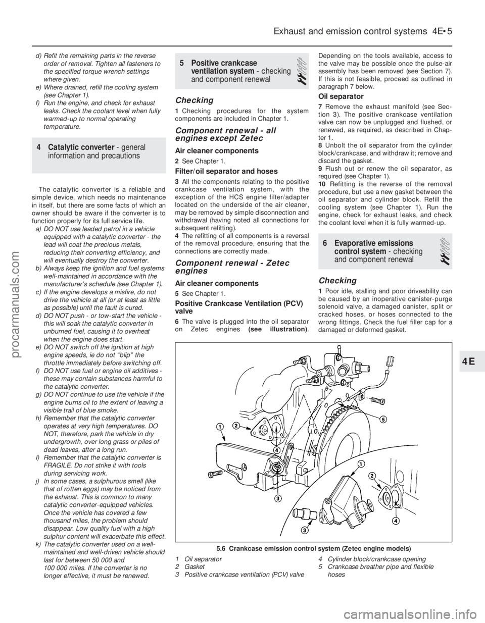
6The valve is plugged into the oil separator
on Zetec engines (see illustration).Depending on the tools available, access to
the valve may be possible once the pulse-air
assembly has been removed (see Section 7).
If this is not feasible, proceed as outlined in
paragraph 7 below.
Oil separator
7
Remove the exhaust manifold (see Sec-
tion 3). The positive crankcase ventilation
valve can now be unplugged and flushed, or
renewed, as required, as described in Chap-
ter 1.
8 Unbolt the oil separator from the cylinder
block/crankcase, and withdraw it; remove and
discard the gasket.
9 Flush out or renew the oil separator, as
required (see Chapter 1).
10 Refitting is the reverse of the removal
procedure, but use a new gasket between the
oil separator and cylinder block. Refill the
cooling system (see Chapter 1). Run the
engine, check for exhaust leaks, and check
the coolant level when it is fully warmed-up.
6 Evaporative emissions control system - checking
and component renewal
2
Checking
1 Poor idle, stalling and poor driveability can
be caused by an inoperative canister-purge
solenoid valve, a damaged canister, split or
cracked hoses, or hoses connected to the
wrong fittings. Check the fuel filler cap for a
damaged or deformed gasket.
Exhaust and emission control systems 4E•5
5.6 Crankcase emission control system (Zetec engine models)
1 Oil separator
2 Gasket
3 Positive crankcase ventilation (PCV) valve 4 Cylinder block/crankcase opening
5 Crankcase breather pipe and flexible
hoses
4E
1595Ford Fiesta Remakeprocarmanuals.com
http://vnx.su
Page 157 of 296
2Fuel loss or fuel odour can be caused by
liquid fuel leaking from fuel lines, a cracked or
damaged canister, an inoperative canister-
purge solenoid valve, or disconnected,
misrouted, kinked or damaged vapour or
control hoses.
3 Inspect each hose attached to the canister
for kinks, leaks and cracks along its entire
length. Repair or renew as necessary.
4 Inspect the canister. If it is cracked or
damaged, renew it. Look for fuel leaking from
the bottom of the canister. If fuel is leaking,
renew the canister, and check the hoses and
hose routing.
5 If the canister-purge solenoid valve is
thought to be faulty, unplug its electrical
connector and disconnect its vacuum hoses.
Connect a battery directly across the valve
terminals. Check that air can flow through the
valve passages when the solenoid is thus
energised, and that nothing can pass when
the solenoid is not energised.
6 Further testing should be left to a dealer
service department.
Component renewal
Charcoal canister-purge solenoid
valve
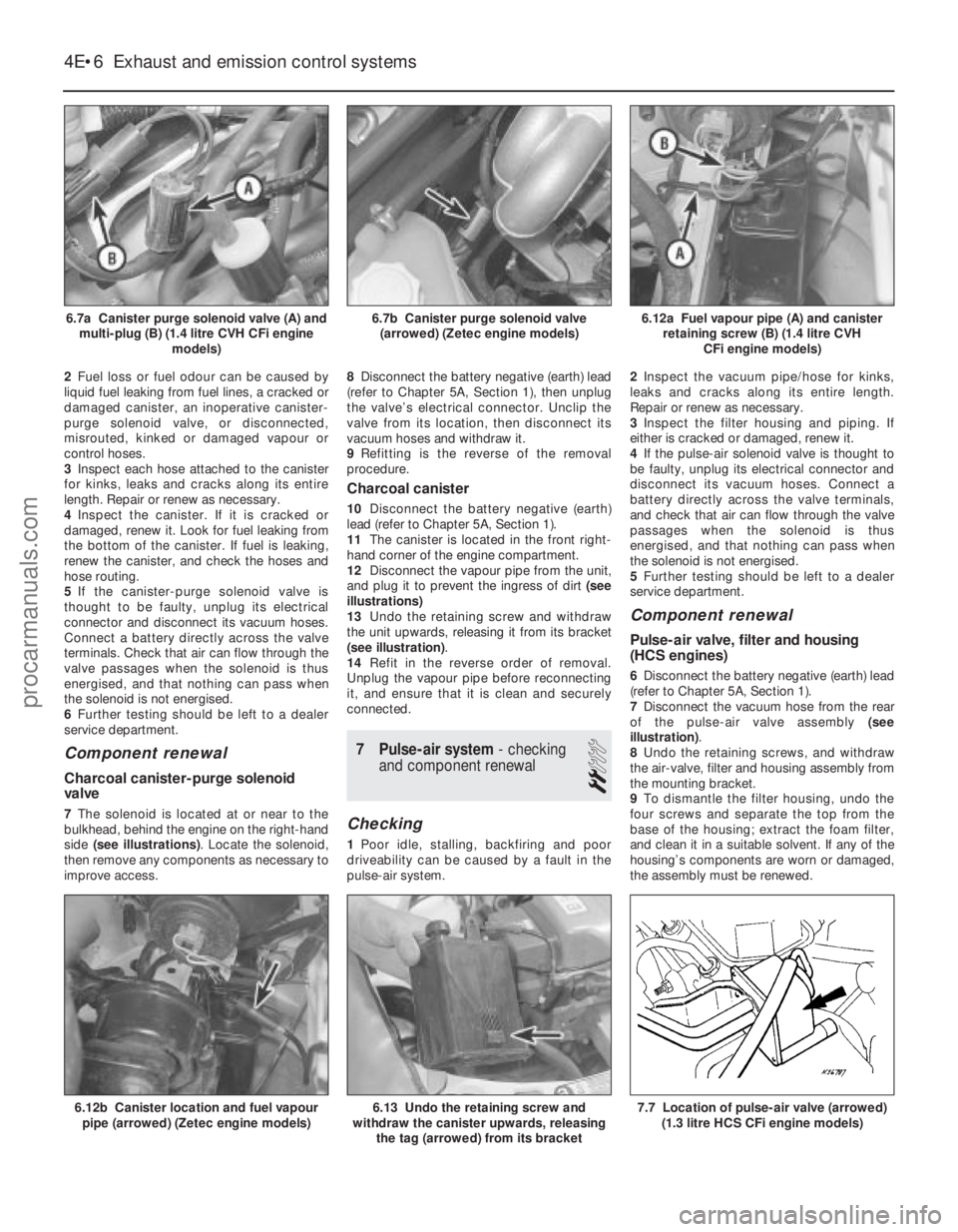
7 The solenoid is located at or near to the
bulkhead, behind the engine on the right-hand
side (see illustrations) . Locate the solenoid,
then remove any components as necessary to
improve access. 8
Disconnect the battery negative (earth) lead
(refer to Chapter 5A, Section 1), then unplug
the valve’s electrical connector. Unclip the
valve from its location, then disconnect its
vacuum hoses and withdraw it.
9 Refitting is the reverse of the removal
procedure.
Charcoal canister
10 Disconnect the battery negative (earth)
lead (refer to Chapter 5A, Section 1).
11 The canister is located in the front right-
hand corner of the engine compartment.
12 Disconnect the vapour pipe from the unit,
and plug it to prevent the ingress of dirt (see
illustrations)
13 Undo the retaining screw and withdraw
the unit upwards, releasing it from its bracket
(see illustration) .
14 Refit in the reverse order of removal.
Unplug the vapour pipe before reconnecting
it, and ensure that it is clean and securely
connected.
7 Pulse-air system - checking
and component renewal
2
Checking
1 Poor idle, stalling, backfiring and poor
driveability can be caused by a fault in the
pulse-air system. 2
Inspect the vacuum pipe/hose for kinks,
leaks and cracks along its entire length.
Repair or renew as necessary.
3 Inspect the filter housing and piping. If
either is cracked or damaged, renew it.
4 If the pulse-air solenoid valve is thought to
be faulty, unplug its electrical connector and
disconnect its vacuum hoses. Connect a
battery directly across the valve terminals,
and check that air can flow through the valve
passages when the solenoid is thus
energised, and that nothing can pass when
the solenoid is not energised.
5 Further testing should be left to a dealer
service department.
Component renewal
Pulse-air valve, filter and housing
(HCS engines)
6 Disconnect the battery negative (earth) lead
(refer to Chapter 5A, Section 1).
7 Disconnect the vacuum hose from the rear
of the pulse-air valve assembly (see
illustration) .
8 Undo the retaining screws, and withdraw
the air-valve, filter and housing assembly from
the mounting bracket.
9 To dismantle the filter housing, undo the
four screws and separate the top from the
base of the housing; extract the foam filter,
and clean it in a suitable solvent. If any of the
housing’s components are worn or damaged,
the assembly must be renewed.
4E•6 Exhaust and emission control systems
7.7 Location of pulse-air valve (arrowed) (1.3 litre HCS CFi engine models)6.13 Undo the retaining screw and
withdraw the canister upwards, releasing
the tag (arrowed) from its bracket6.12b Canister location and fuel vapourpipe (arrowed) (Zetec engine models)
6.12a Fuel vapour pipe (A) and canister retaining screw (B) (1.4 litre CVH CFi engine models)6.7b Canister purge solenoid valve(arrowed) (Zetec engine models)6.7a Canister purge solenoid valve (A) and multi-plug (B) (1.4 litre CVH CFi engine models)
1595Ford Fiesta Remakeprocarmanuals.com
http://vnx.su
Page 271 of 296
1595 Ford Fiesta Remake
The jack supplied with the vehicle tool kit
should only be used for changing the
roadwheels - see “Wheel changing” at the
front of this manual. When jacking up the
vehicle to carry out repair or maintenance
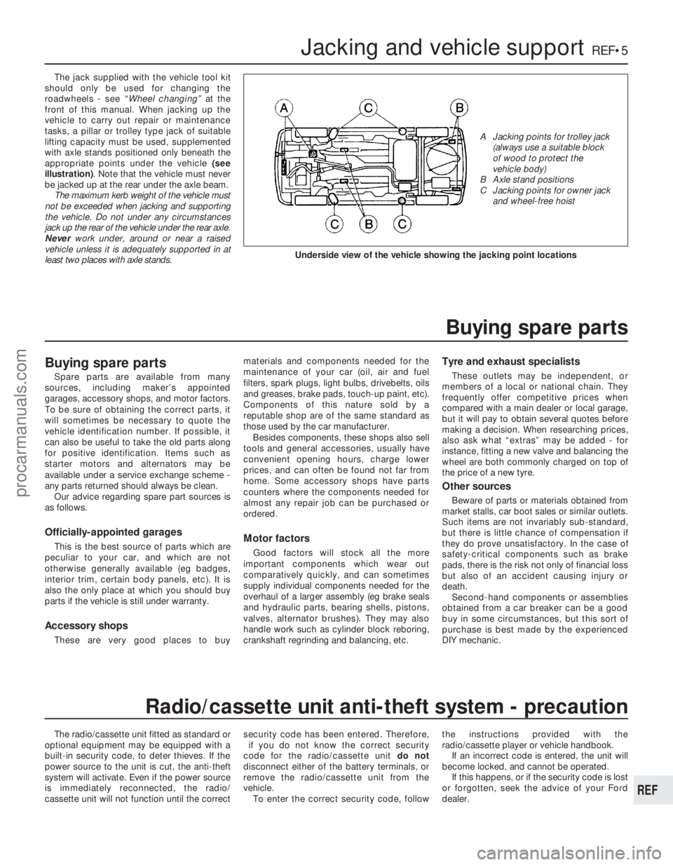
tasks, a pillar or trolley type jack of suitable
lifting capacity must be used, supplemented
with axle stands positioned only beneath the
appropriate points under the vehicle (see
illustration) . Note that the vehicle must never
be jacked up at the rear under the axle beam. The maximum kerb weight of the vehicle must
not be exceeded when jacking and supporting
the vehicle. Do not under any circumstances
jack up the rear of the vehicle under the rear axle.
Never work under, around or near a raised
vehicle unless it is adequately supported in at
least two places with axle stands.
The radio/cassette unit fitted as standard or
optional equipment may be equipped with a
built-in security code, to deter thieves. If the
power source to the unit is cut, the anti-theft
system will activate. Even if the power source
is immediately reconnected, the radio/
cassette unit will not function until the correct security code has been entered. Therefore,
if you do not know the correct security
code for the radio/cassette unit do not
disconnect either of the battery terminals, or
remove the radio/cassette unit from the
vehicle. To enter the correct security code, follow the instructions provided with the
radio/cassette player or vehicle handbook.
If an incorrect code is entered, the unit will
become locked, and cannot be operated.
If this happens, or if the security code is lost
or forgotten, seek the advice of your Ford
dealer.
Jacking and vehicle supportREF•5
REF
Radio/cassette unit anti-theft system - precaution
Underside view of the vehicle showing the jacking point locations
A Jacking points for trolley jack (always use a suitable block
of wood to protect the
vehicle body)
B Axle stand positions
C Jacking points for owner jack and wheel-free hoist
Buying spare parts
Spare parts are available from many
sources, including maker’s appointed
garages, accessory shops, and motor factors.
To be sure of obtaining the correct parts, it
will sometimes be necessary to quote the
vehicle identification number. If possible, it
can also be useful to take the old parts along
for positive identification. Items such as
starter motors and alternators may be
available under a service exchange scheme -
any parts returned should always be clean.
Our advice regarding spare part sources is
as follows.
Officially-appointed garages
This is the best source of parts which are
peculiar to your car, and which are not
otherwise generally available (eg badges,
interior trim, certain body panels, etc). It is
also the only place at which you should buy
parts if the vehicle is still under warranty.
Accessory shops
These are very good places to buy materials and components needed for the
maintenance of your car (oil, air and fuel
filters, spark plugs, light bulbs, drivebelts, oils
and greases, brake pads, touch-up paint, etc).
Components of this nature sold by a
reputable shop are of the same standard as
those used by the car manufacturer.
Besides components, these shops also sell
tools and general accessories, usually have
convenient opening hours, charge lower
prices, and can often be found not far from
home. Some accessory shops have parts
counters where the components needed for
almost any repair job can be purchased or
ordered.
Motor factors
Good factors will stock all the more
important components which wear out
comparatively quickly, and can sometimes
supply individual components needed for the
overhaul of a larger assembly (eg brake seals
and hydraulic parts, bearing shells, pistons,
valves, alternator brushes). They may also
handle work such as cylinder block reboring,
crankshaft regrinding and balancing, etc.
Tyre and exhaust specialists
These outlets may be independent, or
members of a local or national chain. They
frequently offer competitive prices when
compared with a main dealer or local garage,
but it will pay to obtain several quotes before
making a decision. When researching prices,
also ask what “extras” may be added - for
instance, fitting a new valve and balancing the
wheel are both commonly charged on top of
the price of a new tyre.
Other sources
Beware of parts or materials obtained from
market stalls, car boot sales or similar outlets.
Such items are not invariably sub-standard,
but there is little chance of compensation if
they do prove unsatisfactory. In the case of
safety-critical components such as brake
pads, there is the risk not only of financial loss
but also of an accident causing injury or
death. Second-hand components or assemblies
obtained from a car breaker can be a good
buy in some circumstances, but this sort of
purchase is best made by the experienced
DIY mechanic.
Buying spare parts
procarmanuals.com
http://vnx.su
Page 279 of 296
1595 Ford Fiesta Remake
MOT test checksREF•13
REF
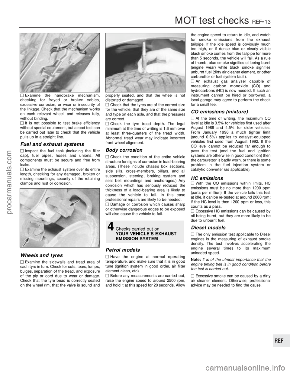
MExamine the handbrake mechanism,
checking for frayed or broken cables,
excessive corrosion, or wear or insecurity of
the linkage. Check that the mechanism works
on each relevant wheel, and releases fully,
without binding.
M It is not possible to test brake efficiency
without special equipment, but a road test can
be carried out later to check that the vehicle
pulls up in a straight line.
Fuel and exhaust systems
M Inspect the fuel tank (including the filler
cap), fuel pipes, hoses and unions. All
components must be secure and free fr om
leaks.
M Examine the exhaust system over its entire
length, checking for any damaged, broken or
missing mountings, security of the retaining
clamps and rust or corrosion.
Wheels and tyres
M Examine the sidewalls and tread area of
each tyre in turn. Check for cuts, tears, lumps,
bulges, separation of the tread, and exposure
of the ply or cord due to wear or damage.
Check that the tyre bead is correctly seated
on the wheel rim, that the valve is sound and pr
operly seated, and that the wheel is not
distorted or damaged.
M Check that the tyres are of the correct size
for the vehicle, that they are of the same size
and type on each axle, and that the pressur es
ar e correct.
M Check the tyre tread depth. The legal
minimum at the time of writing is 1.6 mm over
at least three-quarters of the tread width.
Abnormal tread wear may indicate incorrect
fr ont wheel alignment.
Body corrosion
M Check the condition of the entire vehicle
structur e for signs of corrosion in load-bearing
ar eas. (These include chassis box sections,
side sills, cross-members, pillars, and all
suspension, steering, braking system and
seat belt mountings and anchorages.) Any
corrosion which has seriously reduced the
thickness of a load-bearing area is likely to
cause the vehicle to fail. In this case
pr ofessional repairs are likely to be needed.
M Damage or corrosion which causes sharp
or otherwise dangerous edges to be exposed
will also cause the vehicle to fail.
Petrol models
M Have the engine at normal operating
temperatur e, and make sure that it is in good
tune (ignition system in good order, air filter
element clean, etc).
M Befor e any measurements are carried out,
raise the engine speed to around 2500 rpm,
and hold it at this speed for 20 seconds. Allow the engine speed to return to idle, and watch
for smoke emissions from the exhaust
tailpipe. If the idle speed is obviously much
too high, or if dense blue or clearly-visible
black smoke comes from the tailpipe for more
than 5 seconds, the vehicle will fail. As a rule
of thumb, blue smoke signifies oil being burnt
(engine wear) while black smoke signifies
unbur nt fuel (dirty air cleaner element, or other
carbur ettor or fuel system fault).
M An exhaust gas analyser capable of
measuring carbon monoxide (CO) and
hydr ocarbons (HC) is now needed. If such an
instrument cannot be hired or borrowed, a
local garage may agree to perform the check
for a small fee.
CO emissions (mixture)
M At the time of writing, the maximum CO
level at idle is 3.5% for vehicles first used after
August 1986 and 4.5% for older vehicles.
Fr om January 1996 a much tighter limit
(ar ound 0.5%) applies to catalyst-equipped
vehicles first used from August 1992. If the
CO level cannot be reduced far enough to
pass the test (and the fuel and ignition
systems are otherwise in good condition) then
the carburettor is badly worn, or there is some
pr oblem in the fuel injection system or
catalytic converter (as applicable).
HC emissionsM With the CO emissions within limits, HC
emissions must be no more than 1200 ppm
(parts per million). If the vehicle fails this test
at idle, it can be re-tested at around 2000 rpm;
if the HC level is then 1200 ppm or less, this
counts as a pass.
M Excessive HC emissions can be caused by
oil being burnt, but they are more likely to be
due to unburnt fuel.
Diesel models
M The only emission test applicable to Diesel
engines is the measuring of exhaust smoke
density . The test involves accelerating the
engine several times to its maximum
unloaded speed.
Note: It is of the utmost importance that the
engine timing belt is in good condition before
the test is carried out.
M
Excessive smoke can be caused by a dirty
air cleaner element. Otherwise, professional
advice may be needed to find the cause.
4Checks carried out on
YOUR VEHICLE’S EXHAUST
EMISSION SYSTEM
procarmanuals.com
http://vnx.su
Page 281 of 296
1595 Ford Fiesta Remake
failure of components such as fuses or spark
plugs may only be pointers to some
underlying fault.
The pages which follow provide an easy
reference guide to the more common
problems which may occur during the
operation of the vehicle. These problems and
their possible causes are grouped under
headings denoting various components or
systems, such as Engine, Cooling system,
etc. The Chapter and/or Section which deals
with the problem is also shown in brackets.
Whatever the fault, certain basic principles
apply. These are as follows:
Verify the fault . This is simply a matter of
being sure that you know what the symptoms are before starting work. This is particularly
important if you are investigating a fault for
someone else, who may not have described it
very accurately.
Don’t overlook the obvious . For example, if
the vehicle won’t start, is there petrol in the
tank? (Don’t take anyone else’s word on this
particular point, and don’t trust the fuel gauge
either!) If an electrical fault is indicated, look
for loose or broken wires before digging out
the test gear. Cure the disease, not the symptom .
Substituting a flat battery with a fully-charged
one will get you off the hard shoulder, but if
the underlying cause is not attended to, the
new battery will go the same way. Similarly, changing oil-fouled spark plugs for a new set
will get you moving again, but remember that
the reason for the fouling (if it wasn’t simply an
incorrect grade of plug) will have to be
established and corrected.
Don’t take anything for granted . Particularly,
don’t forget that a “new” component may
itself be defective (especially if it’s been
rattling around in the boot for months), and
don’t leave components out of a fault
diagnosis sequence just because they are
new or recently fitted. When you do finally
diagnose a difficult fault, you’ll probably
realise that all the evidence was there from
the start.
Fault findingREF•15
REF
Engine
Engine fails to rotate when attempting to start
m
m Battery terminal connections loose or corroded (Chapter 5A).
m
m Battery discharged or faulty (Chapter 5A).
m
m Broken, loose or disconnected wiring in the starting circuit
(Chapter 5A).
m m Defective starter solenoid or switch (Chapter 5A).
m
m Defective starter motor (Chapter 5A).
m
m Flywheel ring gear or starter pinion teeth loose or broken
(Chapters 2A, 2B, 2C or 5A).
m m Engine earth strap broken or disconnected (Chapter 5A).
m
m Automatic transmission not in Park/Neutral position, or starter
inhibitor switch faulty (Chapter 7B).
Engine rotates, but will not start
m mFuel tank empty.
m
m Battery discharged (engine rotates slowly) (Chapter 5A).
m
m Battery terminal connections loose or corroded (Chapter 5A).
m
m Ignition components damp or damaged (Chapters 1 and 5B).
m
m Broken, loose or disconnected wiring in the ignition circuit
(Chapters 1 and 5B).
m m Worn, faulty or incorrectly-gapped spark plugs (Chapter 1).
m
m Major mechanical failure (eg camshaft drive) (Chapters 2A, 2B
or 2C).
Engine difficult to start when cold
m mBattery discharged (Chapter 5A).
m
m Battery terminal connections loose or corroded (Chapter 5A).
m
m Worn, faulty or incorrectly-gapped spark plugs (Chapter 1).
m
m Other ignition system fault (Chapters 1 and 5B).
m
m Engine management system fault (Chapters 1, 4A, 4B, 4C, 4D, 4E
or 5B).
m m Low cylinder compressions (Chapters 2A, 2B or 2C).
Engine difficult to start when hot
m
mAir filter element dirty or clogged (Chapter 1).
m
m Engine management system fault (Chapters 1, 4A, 4B, 4C, 4D, 4E
or 5B).
m m Low cylinder compressions (Chapters 2A, 2B or 2C).
m
m Faulty hydraulic tappet(s) (Chapters 2B or 2C).
Starter motor noisy or excessively-rough in
engagement
m mFlywheel ring gear or starter pinion teeth loose or broken
(Chapters 2A, 2B, 2C or 5A).
m m Starter motor mounting bolts loose or missing (Chapter 5A).
m
m Starter motor internal components worn or damaged (Chapter 5A).
Engine starts but stops immediately
m
mLoose or faulty electrical connections in the ignition circuit
(Chapters 1 and 5B).
m m Engine management system fault (Chapters 1, 4A, 4B, 4C, 4D, 4E
or 5B).
m m Vacuum leak at the inlet manifold (Chapters 1, 4A, 4B, 4C, 4D or 4E).
Engine idles erratically
m
mEngine management system fault (Chapters 1, 4A, 4B, 4C, 4D, 4E
or 5B).
m m Air filter element clogged (Chapter 1).
m
m Vacuum leak at the inlet manifold or associated hoses (Chap-
ters 1, 4A, 4B, 4C, 4D or 4E).
m m Worn, faulty or incorrectly-gapped spark plugs (Chapter 1).
m
m Incorrect valve clearances (Chapter 2A).
m
m Faulty hydraulic tappet(s) (Chapters 2B or 2C).
m
m Uneven or low cylinder compressions (Chapters 2A, 2B or 2C).
m
m Camshaft lobes worn (Chapters 2A, 2B or 2C).
m
m Timing chain and sprockets worn (Chapter 2A).
m
m Timing belt incorrectly-tensioned (Chapters 2B or 2C).
Engine misfires at idle speed
m
mWorn, faulty or incorrectly-gapped spark plugs (Chapter 1).
m
m Faulty spark plug HT leads (Chapter 1).
m
m Engine management system fault (Chapters 1, 4A, 4B, 4C, 4D, 4E
or 5B).
m m Vacuum leak at the inlet manifold or associated hoses (Chap-
ters 1, 4A, 4B, 4C, 4D or 4E).
m m Incorrect valve clearances (Chapter 2A).
m
m Faulty hydraulic tappet(s) (Chapters 2B or 2C).
m
m Uneven or low cylinder compressions (Chapters 2A, 2B and 2C).
m
m Disconnected, leaking or perished crankcase ventilation hoses
(Chapters 1 and 4E).
Engine misfires throughout the driving speed range
m mFuel filter choked (Chapter 1).
m
m Fuel pump faulty or delivery pressure low (Chapters 4A, 4B, 4C or 4D).\
m
m Fuel tank vent blocked or fuel pipes restricted (Chapters 4A, 4B,
4C, 4D or 4E).
m m Vacuum leak at the inlet manifold or associated hoses (Chap-
ters 1, 4A, 4B, 4C, 4D or 4E).
m m Worn, faulty or incorrectly-gapped spark plugs (Chapter 1).
m
m Faulty spark plug HT leads (Chapter 1).
m
m Faulty ignition coil (Chapter 5B).
m
m Engine management system fault (Chapters 1, 4A, 4B, 4C, 4D, 4E
or 5B).
m m Uneven or low cylinder compressions (Chapters 2A, 2B or 2C).
procarmanuals.com
http://vnx.su
Page 282 of 296
1595 Ford Fiesta Remake
REF•16Fault finding
Cooling system
Overheating
m
mInsufficient coolant in system (Chapter 1).
m
m Thermostat faulty (Chapter 3).
m
m Radiator core blocked or grille restricted (Chapter 3).
m
m Radiator electric cooling fan(s) or coolant temperature sensor
faulty Chapter 3).
m m Engine management system fault (Chapters 1, 4A, 4B, 4C, 4D, 4E
or 5B).
m m Pressure cap faulty (Chapter 3).
m
m Auxiliary drivebelt worn or slipping (Chapter 1).
m
m Inaccurate coolant temperature gauge sender (Chapter 3).
m
m Airlock in cooling system (Chapter 1).
Overcooling
m
mThermostat faulty (Chapter 3).
m
m Inaccurate coolant temperature gauge sender (Chapter 3).
External coolant leakage
m
mDeteriorated or damaged hoses or hose clips (Chapter 1).
m
m Radiator core or heater matrix leaking (Chapter 3).
m
m Pressure cap faulty (Chapter 3).
m
m Water pump seal leaking (Chapter 3).
m
m Boiling due to overheating (Chapter 3).
m
m Core plug leaking (Chapter 2D).
Internal coolant leakage
m
mLeaking cylinder head gasket (Chapters 2A, 2B or 2C).
m
m Cracked cylinder head or cylinder bore (Chapter 2D).
Corrosion
m
mInfrequent draining and flushing (Chapter 1).
m
m Incorrect antifreeze mixture, or inappropriate antifreeze type
(Chapters 1 and 3).
Engine (continued)
Engine hesitates on acceleration
m
m Worn, faulty or incorrectly-gapped spark plugs (Chapter 1).
m
m Engine management system fault (Chapters 1, 4A, 4B, 4C, 4D, 4E
or 5B).
m m Vacuum leak at the inlet manifold or associated hoses (Chap-
ters 1, 4A, 4B, 4C, 4D, 4E or 5B).
Engine stalls
m mEngine management system fault (Chapters 1, 4A, 4B, 4C, 4D, 4E,
or 5B).
m m Vacuum leak at the inlet manifold or associated hoses (Chap-
ters 1, 4A, 4B, 4C, 4D or 4E).
m m Fuel filter choked (Chapter 1).
m
m Fuel pump faulty or delivery pressure low (Chapters 4A, 4B, 4C
or 4D).
m m Fuel tank vent blocked or fuel pipes restricted (Chapters 4A, 4B,
4C. 4D or 4E).
Engine lacks power
m mEngine management system fault (Chapters 1, 4A, 4B, 4C, 4D, 4E
or 5B).
m m Timing chain or belt incorrectly fitted or incorrectly tensioned
(Chapters 2A, 2B or 2C).
m m Fuel filter choked (Chapter 1).
m
m Fuel pump faulty or delivery pressure low (Chapters 4A, 4B, 4C
or 4D).
m m Uneven or low cylinder compressions (Chapters 2A, 2B or 2C).
m
m Worn, faulty or incorrectly-gapped spark plugs (Chapter 1).
m
m Vacuum leak at the inlet manifold or associated hoses (Chap-
ters 1, 4A, 4B, 4C, 4D or 4E).
m m Brakes binding (Chapters 1 and 9).
m
m Clutch slipping (Chapter 6).
m
m Automatic transmission fluid level incorrect (Chapter 1).
Oil pressure warning light illuminated with engine
running
m mLow oil level or incorrect oil grade (Chapter 1).
m
m Faulty oil pressure warning light switch (Chapters 2A, 2B or 2C).
m
m Worn engine bearings and/or oil pump (Chapters 2A, 2B, 2C
or 2D).
m m High engine operating temperature (Chapter 3).
m
m Oil pressure relief valve defective (Chapters 2A, 2B or 2C).
m
m Oil pick-up strainer clogged (Chapters 2A, 2B or 2C).
Engine backfires
m
mEngine management system fault (Chapters 1, 4A, 4B, 4C, 4D, 4E
or 5B).
m m Timing chain or belt incorrectly fitted or incorrectly tensioned
(Chapters 2A, 2B or 2C).
m m Vacuum leak at the inlet manifold or associated hoses (Chap-
ters 1, 4A, 4B, 4C, 4D or 4E).
Engine runs-on after switching off
m mIdle speed excessively high (Chapters 4A, 4B, 4C or 4D).
m
m Engine management system fault (Chapters 1, 4A, 4B, 4C, 4D, 4E
or 5B).
m m Excessive carbon build-up in engine (Chapters 2A, 2B or 2C).
m
m High engine operating temperature (Chapter 3).
Engine noises
Pre-ignition (pinking) or knocking during acceleration or
under load
m mIncorrect grade of fuel (Chapters 4A, 4B, 4C or 4D).
m
m Vacuum leak at the inlet manifold or associated hoses (Chap-
ters 1, 4A, 4B, 4C, 4D or 4E).
m m Excessive carbon build-up in engine (Chapters 2A, 2B or 2C).
Whistling or wheezing noises
m
mLeaking inlet manifold gasket (Chapters 4A, 4B, 4C, 4D).
m
m Leaking exhaust manifold gasket or downpipe-to-manifold joint
(Chapter 4E).
m m Leaking vacuum hose (Chapters 1, 4A, 4B, 4C, 4D, 4E or 9).
m
m Blowing cylinder head gasket (Chapters 2A, 2B or 2C).
Tapping or rattling noises
m
mIncorrect valve clearance adjustment (Chapter 2A).
m
m Faulty hydraulic tappet(s) (Chapters 2B or 2C).
m
m Worn valve gear or camshaft (Chapters 2A, 2B, 2C or 2D).
m
m Worn timing chain, belt or tensioner (Chapters 2A, 2B or 2C).
m
m Ancillary component fault (water pump, alternator, etc) (Chapters 3
and 5A).
Knocking or thumping noises
m mWorn big-end bearings (regular heavy knocking, perhaps less
under load) Chapter 2D).
m m Worn main bearings (rumbling and knocking, perhaps worsening
under load) Chapter 2D).
m m Piston slap (most noticeable when cold) (Chapter 2D).
m
m Ancillary component fault (water pump, alternator, etc) (Chapters 3
and 5A).
procarmanuals.com
http://vnx.su
Page 283 of 296
1595 Ford Fiesta Remake
Fault findingREF•17
REF
Fuel and exhaust systems
Excessive fuel consumption
m
mUnsympathetic driving style, or adverse conditions.
m
m Air filter element dirty or clogged (Chapter 1).
m
m Engine management system fault (Chapters 1, 4A, 4B, 4C, 4D, 4E
or 5B).
m m Tyres under-inflated ( “Weekly Checks”).
Fuel leakage and/or fuel odour
m
mDamaged or corroded fuel tank, pipes or connections (Chapter 1).
m
m Charcoal canister and/or connecting pipes leaking (Chapters 1
and 4E).
Excessive noise or fumes from exhaust system
m mLeaking exhaust system or manifold joints (Chapters 1 or 4E).
m
m Leaking, corroded or damaged silencers or pipe (Chapters 1 or 4E).
m
m Broken mountings, causing body or suspension contact (Chap-
ters 1 or 4E).
Clutch
Pedal travels to floor - no pressure or very little
resistance
m mBroken clutch cable (Chapter 6).
m
m Faulty clutch automatic adjuster (Chapter 6).
m
m Broken clutch release bearing or fork (Chapter 6).
m
m Broken diaphragm spring in clutch pressure plate (Chapter 6).
Clutch fails to disengage (unable to select gears)
m
mFaulty clutch automatic adjuster (Chapter 6).
m
m Clutch disc sticking on transmission input shaft splines (Chapter 6).
m
m Clutch disc sticking to flywheel or pressure plate (Chapter 6).
m
m Faulty pressure plate assembly (Chapter 6).
m
m Clutch release mechanism worn or incorrectly assembled (Chapter 6).
Clutch slips (engine speed increases, with no
increase in vehicle speed)
m mFaulty clutch automatic adjuster (Chapter 6).
m
m Clutch disc linings excessively worn (Chapter 6).
m
m Clutch disc linings contaminated with oil or grease (Chapter 6).
m
m Faulty pressure plate or weak diaphragm spring (Chapter 6).
Judder as clutch is engaged
m
mClutch disc linings contaminated with oil or grease (Chapter 6).
m
m Clutch disc linings excessively worn (Chapter 6).
m
m Clutch cable sticking or frayed (Chapter 6).
m
m Faulty or distorted pressure plate or diaphragm spring (Chapter 6).
m
m Worn or loose engine/transmission mountings (Chapters 2A, 2B
or 2C).
m m Clutch disc hub or transmission input shaft splines worn (Chap-
ter 6).
Noise when depressing or releasing clutch pedal
m mWorn clutch release bearing (Chapter 6).
m
m Worn or dry clutch pedal bushes (Chapter 6).
m
m Faulty pressure plate assembly (Chapter 6).
m
m Pressure plate diaphragm spring broken (Chapter 6).
m
m Broken clutch disc cushioning springs (Chapter 6).
Manual transmission
Noisy in neutral with engine running
m
mInput shaft bearings worn (noise apparent with clutch pedal
released, but not when depressed) (Chapter 7A).*
m m Clutch release bearing worn (noise apparent with clutch pedal
depressed, possibly less when released) (Chapter 6).
Noisy in one particular gear
m mWorn, damaged or chipped gear teeth (Chapter 7A).*
Difficulty engaging gears
m
mClutch fault (Chapter 6).
m
m Worn or damaged gear linkage (Chapter 7A).
m
m Incorrectly-adjusted gear linkage (Chapter 7A).
m
m Worn synchroniser assemblies (Chapter 7A).*
Vibration
m
mLack of oil (Chapter 1).
m
m Worn bearings (Chapter 7A).*
Jumps out of gear
m
mWorn or damaged gear linkage (Chapter 7A).
m
m Incorrectly-adjusted gear linkage (Chapter 7A).
m
m Worn synchroniser assemblies (Chapter 7A).*
m
m Worn selector forks (Chapter 7A).*
Lubricant leaks
m
mLeaking differential side gear oil seal (Chapter 7A).
m
m Leaking housing joint (Chapter 7A).*
m
m Leaking input shaft oil seal (Chapter 7A).*
m
m Leaking selector shaft oil seal (Chapter 7A).
m
m Leaking speedometer drive pinion O-ring (Chapter 7A).
* Although the corrective action necessary to remedy the symptoms
described is beyond the scope of the home mechanic, the above
information should be helpful in isolating the cause of the condition,
so that the owner can communicate clearly with a professional
mechanic.
procarmanuals.com
http://vnx.su
Page 294 of 296
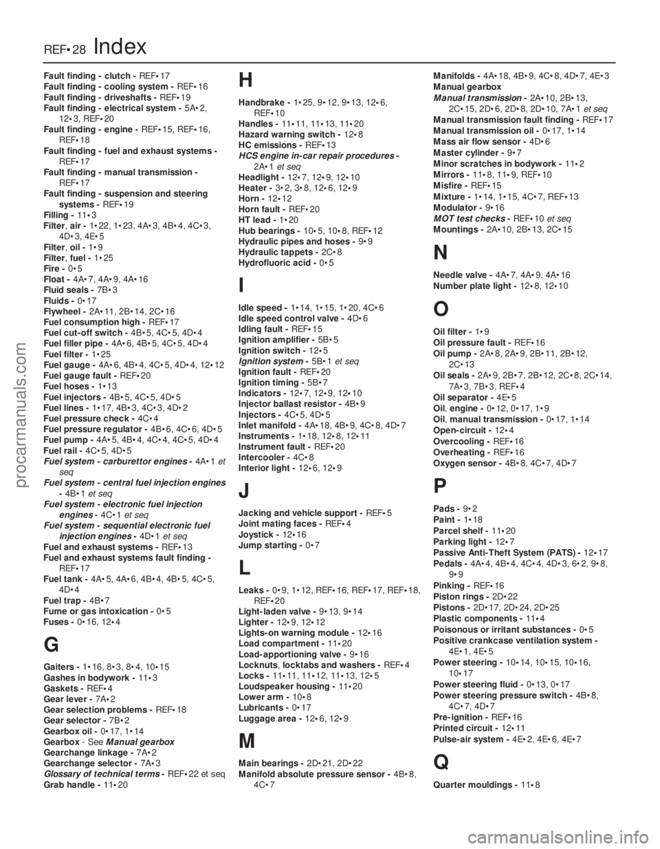
Fault finding - clutch - REF•17
Fault finding - cooling system - REF•16
Fault finding - driveshafts - REF•19
Fault finding - electrical system - 5A•2,
12 •3, REF •20
Fault finding - engine - REF•15, REF•16,
REF•18
Fault finding - fuel and exhaust systems -
REF•17
Fault finding - manual transmission - REF•17
Fault finding - suspension and steering
systems - REF•19
Filling - 11•3
Filter, air -1•22, 1•23, 4A•3, 4B•4, 4C•3,
4D•3, 4E•5
Filter, oil -1•9
Filter, fuel -1•25
Fire - 0•5
Float - 4A•7, 4A•9, 4A•16
Fluid seals - 7B•3
Fluids - 0•17
Flywheel - 2A•11, 2B•14, 2C•16
Fuel consumption high - REF•17
Fuel cut-off switch - 4B•5, 4C•5, 4D•4
Fuel filler pipe - 4A•6, 4B•5, 4C•5, 4D•4
Fuel filter - 1•25
Fuel gauge - 4A•6, 4B•4, 4C•5, 4D•4, 12 •12
Fuel gauge fault - REF•20
Fuel hoses - 1•13
Fuel injectors - 4B•5, 4C•5, 4D•5
Fuel lines - 1•17, 4B•3, 4C•3, 4D•2
Fuel pressure check - 4C•4
Fuel pressure regulator - 4B•6, 4C•6, 4D•5
Fuel pump - 4A•5, 4B•4, 4C•4, 4C•5, 4D•4
Fuel rail - 4C•5, 4D•5
Fuel system - carburettor engines -4A•1 et
seq
Fuel system - central fuel injection engines
-4B•1 et seq
Fuel system - electronic fuel injection engines -4C•1 et seq
Fuel system - sequential electronic fuel
injection engines -4D•1 et seq
Fuel and exhaust systems - REF•13
Fuel and exhaust systems fault finding - REF•17
Fuel tank - 4A•5, 4A•6, 4B•4, 4B•5, 4C•5,
4D•4
Fuel trap - 4B•7
Fume or gas intoxication - 0•5
Fuses - 0•16, 12 •4
G
Gaiters - 1•16, 8•3, 8•4, 10 •15
Gashes in bodywork - 11•3
Gaskets - REF •4
Gear lever - 7A•2
Gear selection problems - REF•18
Gear selector - 7B•2
Gearbox oil - 0•17, 1•14
Gearbox - See Manual gearbox
Gearchange linkage - 7A•2
Gearchange selector - 7A•3
Glossary of technical terms - REF•22 et seq
Grab handle - 11•20
H
Handbrake - 1•25, 9•12, 9•13, 12 •6,
REF•10
Handles - 11•11, 11•13, 11 •20
Hazard warning switch - 12•8
HC emissions - REF•13
HCS engine in-car repair procedures -
2A•1 et seq
Headlight - 12•7, 12 •9, 12 •10
Heater - 3•2, 3•8, 12 •6, 12•9
Horn - 12•12
Horn fault - REF•20
HT lead - 1•20
Hub bearings - 10•5, 10•8, REF •12
Hydraulic pipes and hoses - 9•9
Hydraulic tappets - 2C•8
Hydrofluoric acid - 0•5
I
Idle speed -1•14, 1•15, 1•20, 4C•6
Idle speed control valve - 4D•6
Idling fault - REF•15
Ignition amplifier - 5B•5
Ignition switch - 12•5
Ignition system -5B•1 et seq
Ignition fault - REF•20
Ignition timing - 5B•7
Indicators - 12•7, 12•9, 12 •10
Injector ballast resistor - 4B•9
Injectors - 4C•5, 4D•5
Inlet manifold - 4A•18, 4B•9, 4C•8, 4D•7
Instruments - 1•18, 12•8, 12•11
Instrument fault - REF•20
Intercooler - 4C•8
Interior light - 12•6, 12 •9
J
Jacking and vehicle support - REF•5
Joint mating faces - REF•4
Joystick - 12•16
Jump starting - 0•7
L
Leaks -0•9, 1•12, REF •16, REF•17, REF•18,
REF•20
Light-laden valve - 9•13, 9•14
Lighter - 12•9, 12 •12
Lights-on warning module - 12•16
Load compartment - 11•20
Load-apportioning valve - 9•16
Locknuts ,locktabs and washers - REF•4
Locks - 11•11, 11•12, 11•13, 12 •5
Loudspeaker housing - 11•20
Lower arm - 10•8
Lubricants - 0•17
Luggage area - 12•6, 12•9
M
Main bearings - 2D•21, 2D•22
Manifold absolute pressure sensor - 4B•8,
4C•7 Manifolds -
4A•18, 4B•9, 4C•8, 4D•7, 4E•3
Manual gearbox
Manual transmission -2A•10, 2B•13,
2C•15, 2D•6, 2D•8, 2D•10, 7A•1 et seq
Manual transmission fault finding - REF•17
Manual transmission oil - 0•17, 1•14
Mass air flow sensor - 4D•6
Master cylinder - 9•7
Minor scratches in bodywork - 11•2
Mirrors - 11 •8, 11•9, REF •10
Misfire - REF•15
Mixture - 1•14, 1•15, 4C•7, REF•13
Modulator - 9•16
MOT test checks - REF•10et seq
Mountings - 2A•10, 2B•13, 2C•15
N
Needle valve - 4A•7, 4A•9, 4A•16
Number plate light - 12•8, 12 •10
O
Oil filter - 1•9
Oil pressure fault - REF•16
Oil pump - 2A•8, 2A•9, 2B•11, 2B•12,
2C•13
Oil seals - 2A•9, 2B•7, 2B•12, 2C•8, 2C•14,
7A•3, 7B•3, REF •4
Oil separator - 4E•5
Oil, engine - 0•12, 0•17, 1•9
Oil, manual transmission - 0•17, 1•14
Open-circuit - 12•4
Overcooling - REF•16
Overheating - REF•16
Oxygen sensor - 4B•8, 4C•7, 4D•7
P
Pads -9•2
Paint - 1•18
Parcel shelf - 11•20
Parking light - 12•7
Passive Anti-Theft System (PATS) - 12•17
Pedals - 4A•4, 4B•4, 4C•4, 4D•3, 6•2, 9•8,
9•9
Pinking - REF•16
Piston rings - 2D•22
Pistons - 2D•17, 2D•24, 2D•25
Plastic components - 11•4
Poisonous or irritant substances - 0•5
Positive crankcase ventilation system - 4E•1, 4E•5
Power steering - 10•14, 10•15, 10•16,
10 •17
Power steering fluid - 0•13, 0•17
Power steering pressure switch - 4B•8,
4C•7, 4D•7
Pre-ignition - REF•16
Printed circuit - 12•11
Pulse-air system - 4E•2, 4E•6, 4E•7
Q
Quarter mouldings - 11•8
REF•28Index
1595 Ford Fiesta Remakeprocarmanuals.com
http://vnx.su