fuel filter FORD FIESTA 1989 Service User Guide
[x] Cancel search | Manufacturer: FORD, Model Year: 1989, Model line: FIESTA, Model: FORD FIESTA 1989Pages: 296, PDF Size: 10.65 MB
Page 26 of 296
the specified type of fluid. It is essential that
no dirt is introduced into the transmission
during this operation.
7Depending on the extent to which the fluid
was allowed to drain, it is possible that the
amount of fluid required when filling the
transmission may be more than the specified
amount (see “Lubricants, fluids and tyre
pressures” ). However, due to fluid remaining in
the system, it is more likely that less than the
specified amount will be required. Add about
half the specified amount, then run the engine
up to its normal operating temperature and
check the level on the dipstick. When the level
approaches the maximum mark, proceed as
detailed in Section 20 to check the level and
complete the final topping-up as described.
27 Handbrake adjustment
3
1 Chock the front wheels then jack up the
rear of the car and support it on axle stands
(see “Jacking and Vehicle Support” ). Fully
release the handbrake.
2 Check that the handbrake cables are
correctly routed and secured by the retaining
clips at the appropriate points under the vehicle.
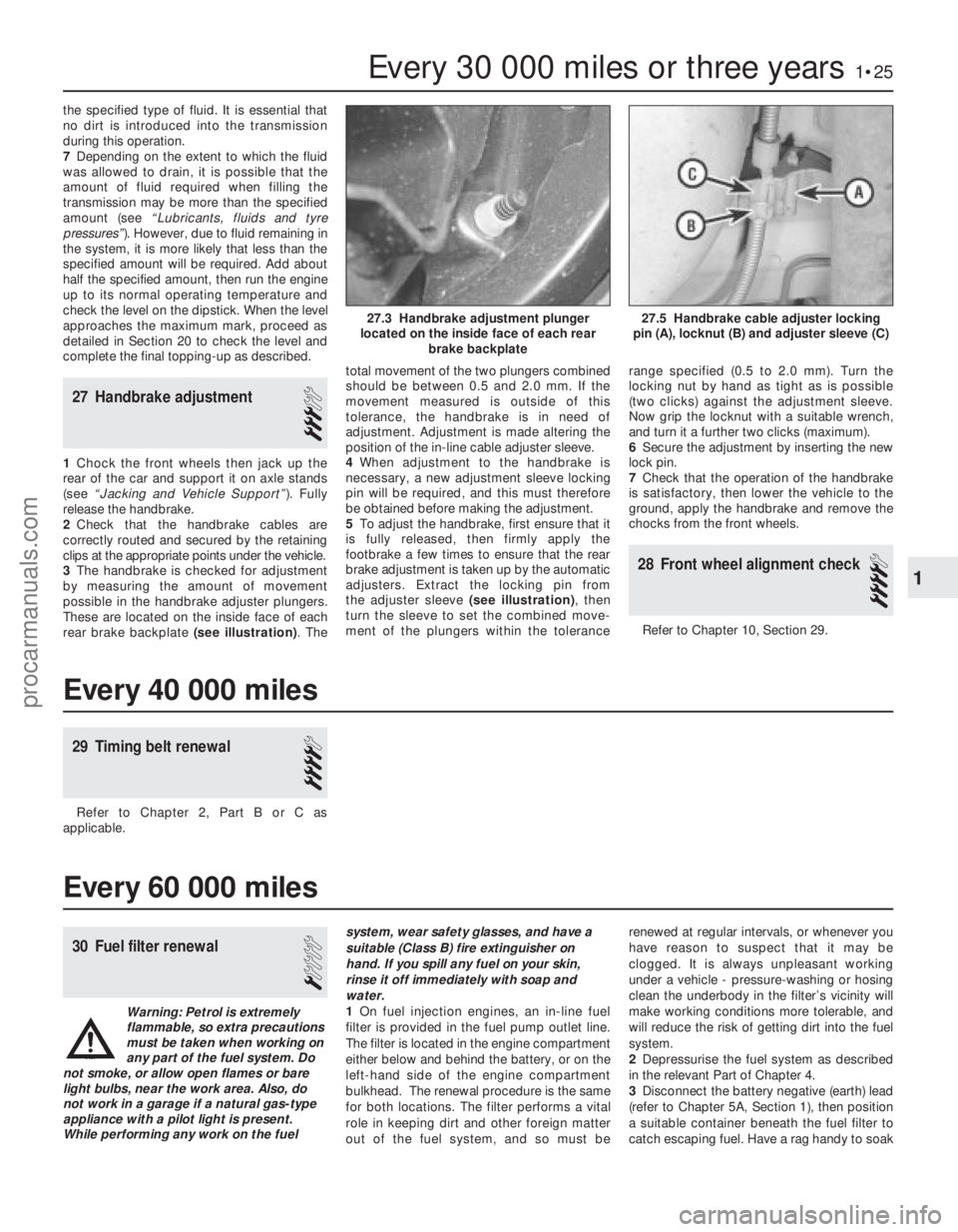
3 The handbrake is checked for adjustment
by measuring the amount of movement
possible in the handbrake adjuster plungers.
These are located on the inside face of each
rear brake backplate (see illustration) . Thetotal movement of the two plungers combined
should be between 0.5 and 2.0 mm. If the
movement measured is outside of this
tolerance, the handbrake is in need of
adjustment. Adjustment is made altering the
position of the in-line cable adjuster sleeve.
4
When adjustment to the handbrake is
necessary, a new adjustment sleeve locking
pin will be required, and this must therefore
be obtained before making the adjustment.
5 To adjust the handbrake, first ensure that it
is fully released, then firmly apply the
footbrake a few times to ensure that the rear
brake adjustment is taken up by the automatic
adjusters. Extract the locking pin from
the adjuster sleeve (see illustration), then
turn the sleeve to set the combined move-
ment of the plungers within the tolerance range specified (0.5 to 2.0 mm). Turn the
locking nut by hand as tight as is possible
(two clicks) against the adjustment sleeve.
Now grip the locknut with a suitable wrench,
and turn it a further two clicks (maximum).
6
Secure the adjustment by inserting the new
lock pin.
7 Check that the operation of the handbrake
is satisfactory, then lower the vehicle to the
ground, apply the handbrake and remove the
chocks from the front wheels.
28 Front wheel alignment check
4
Refer to Chapter 10, Section 29.
Every 30 000 miles or three years1•25
27.5 Handbrake cable adjuster locking
pin (A), locknut (B) and adjuster sleeve (C)27.3 Handbrake adjustment plunger
located on the inside face of each rear brake backplate
1
1595Ford Fiesta Remake
Every 40 000 miles
29 Timing belt renewal
4
Refer to Chapter 2, Part B or C as
applicable.
Every 60 000 miles
30 Fuel filter renewal
1
Warning: Petrol is extremely
flammable, so extra precautions
must be taken when working on
any part of the fuel system. Do
not smoke, or allow open flames or bare
light bulbs, near the work area. Also, do
not work in a garage if a natural gas-type appliance with a pilot light is present.
While performing any work on the fuel system, wear safety glasses, and have a
suitable (Class B) fire extinguisher on
hand. If you spill any fuel on your skin,
rinse it off immediately with soap and
water.
1
On fuel injection engines, an in-line fuel
filter is provided in the fuel pump outlet line.
The filter is located in the engine compartment
either below and behind the battery, or on the
left-hand side of the engine compartment
bulkhead. The renewal procedure is the same
for both locations. The filter performs a vital
role in keeping dirt and other foreign matter
out of the fuel system, and so must be renewed at regular intervals, or whenever you
have reason to suspect that it may be
clogged. It is always unpleasant working
under a vehicle - pressure-washing or hosing
clean the underbody in the filter’s vicinity will
make working conditions more tolerable, and
will reduce the risk of getting dirt into the fuel
system.
2
Depressurise the fuel system as described
in the relevant Part of Chapter 4.
3 Disconnect the battery negative (earth) lead
(refer to Chapter 5A, Section 1), then position
a suitable container beneath the fuel filter to
catch escaping fuel. Have a rag handy to soak
procarmanuals.com
http://vnx.su
Page 27 of 296
up the fuel when the feed and outlet pipe
unions are disconnected.
4On models without quick-release couplings
on the fuel lines, slowly slacken the fuel feed
pipe union allowing the pressure in the fuel
pipe to reduce. When the pressure is fully
released, disconnect the fuel feed and outlet
pipe unions.
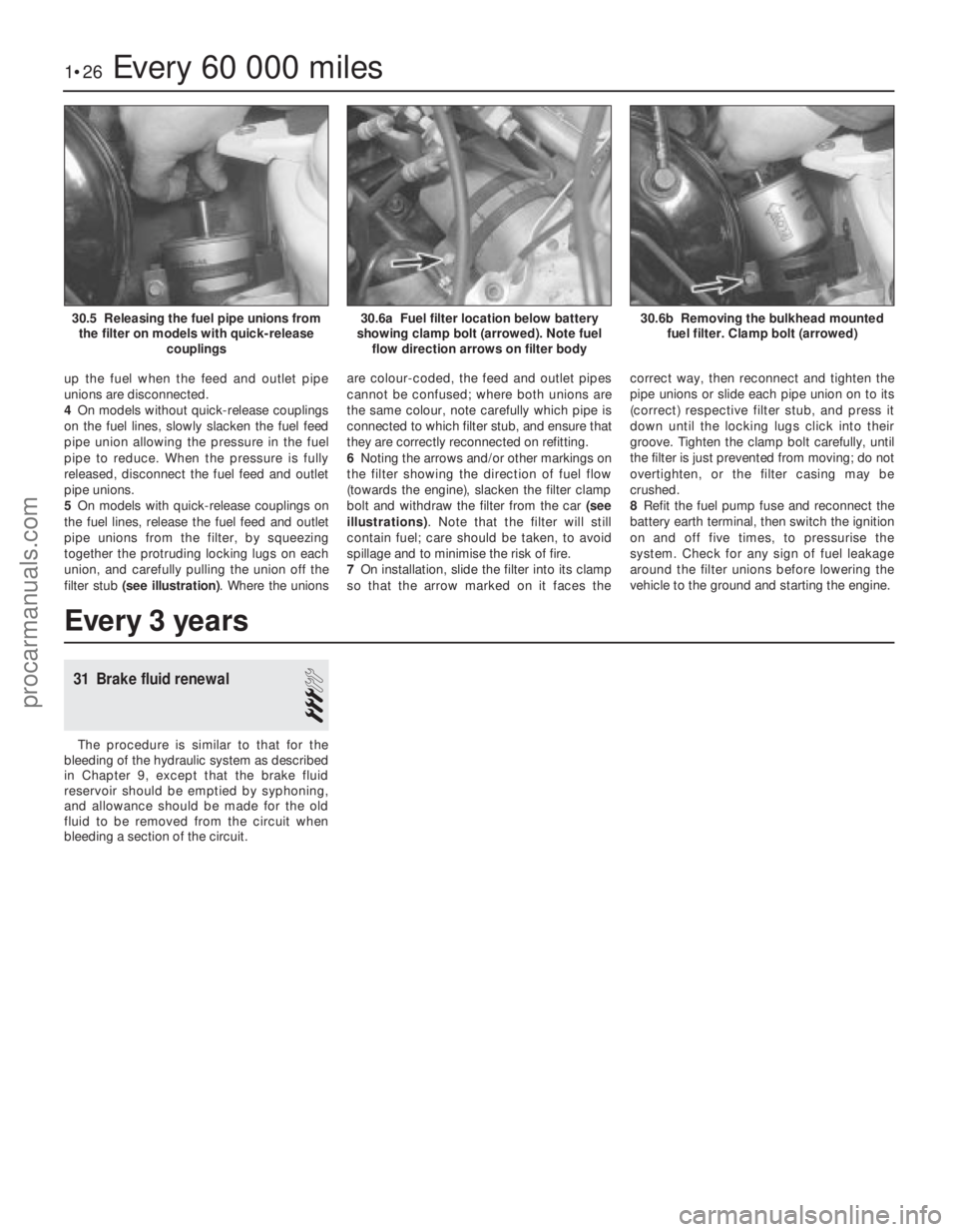
5 On models with quick-release couplings on
the fuel lines, release the fuel feed and outlet
pipe unions from the filter, by squeezing
together the protruding locking lugs on each
union, and carefully pulling the union off the
filter stub (see illustration) . Where the unions are colour-coded, the feed and outlet pipes
cannot be confused; where both unions are
the same colour, note carefully which pipe is
connected to which filter stub, and ensure that
they are correctly reconnected on refitting.
6
Noting the arrows and/or other markings on
the filter showing the direction of fuel flow
(towards the engine), slacken the filter clamp
bolt and withdraw the filter from the car (see
illustrations) . Note that the filter will still
contain fuel; care should be taken, to avoid
spillage and to minimise the risk of fire.
7 On installation, slide the filter into its clamp
so that the arrow marked on it faces the correct way, then reconnect and tighten the
pipe unions or slide each pipe union on to its
(correct) respective filter stub, and press it
down until the locking lugs click into their
groove. Tighten the clamp bolt carefully, until
the filter is just prevented from moving; do not
overtighten, or the filter casing may be
crushed.
8
Refit the fuel pump fuse and reconnect the
battery earth terminal, then switch the ignition
on and off five times, to pressurise the
system. Check for any sign of fuel leakage
around the filter unions before lowering the
vehicle to the ground and starting the engine.
1•26Every 60 000 miles
30.6b Removing the bulkhead mounted fuel filter. Clamp bolt (arrowed)30.6a Fuel filter location below battery
showing clamp bolt (arrowed). Note fuel flow direction arrows on filter body30.5 Releasing the fuel pipe unions fromthe filter on models with quick-release couplings
1595Ford Fiesta Remake
Every 3 years
31 Brake fluid renewal
3
The procedure is similar to that for the
bleeding of the hydraulic system as described
in Chapter 9, except that the brake fluid
reservoir should be emptied by syphoning,
and allowance should be made for the old
fluid to be removed from the circuit when
bleeding a section of the circuit.
procarmanuals.com
http://vnx.su
Page 28 of 296

2A
1595Ford Fiesta Remake
General
Engine type . . . . . . . . . . . . . . . . . . . . . . . . . . . . . . . . . . . .\
. . . . . . . . . . . Four-cylinder, in-line overhead valve
Engine code:1.0 litre carburettor models . . . . . . . . . . . . . . . . . . . . . . . . . . . . . . . . . TLB
1.1 litre carburettor models . . . . . . . . . . . . . . . . . . . . . . . . . . . . . . . . . GUE or GUD
1.1 litre CFi fuel injection models . . . . . . . . . . . . . . . . . . . . . . . . . . . . G6A
1.3 litre carburettor models . . . . . . . . . . . . . . . . . . . . . . . . . . . . . . . . . JBC
1.3 litre CFi fuel injection models . . . . . . . . . . . . . . . . . . . . . . . . . . . . J6B
Capacity: 1.0 litre models . . . . . . . . . . . . . . . . . . . . . . . . . . . . . . . . . . . .\
. . . . . . 999 cc
1.1 litre models . . . . . . . . . . . . . . . . . . . . . . . . . . . . . . . . . . . .\
. . . . . . 1118 cc
1.3 litre models . . . . . . . . . . . . . . . . . . . . . . . . . . . . . . . . . . . .\
. . . . . . 1297 cc
Bore:
1.0 and 1.1 litre models . . . . . . . . . . . . . . . . . . . . . . . . . . . . . . . . . . . 68.68 mm
1.3 litre models . . . . . . . . . . . . . . . . . . . . . . . . . . . . . . . . . . . .\
. . . . . . 73.96 mm
Stroke:
1.0 litre models . . . . . . . . . . . . . . . . . . . . . . . . . . . . . . . . . . . .\
. . . . . . 67.40 mm
1.1 and 1.3 litre models . . . . . . . . . . . . . . . . . . . . . . . . . . . . . . . . . . . 75.48 mm
Compression ratio:
Carburettor models . . . . . . . . . . . . . . . . . . . . . . . . . . . . . . . . . . . .\
. . . 9.5:1
CFi fuel injection models . . . . . . . . . . . . . . . . . . . . . . . . . . . . . . . . . . . 8.8:1
Firing order . . . . . . . . . . . . . . . . . . . . . . . . . . . . . . . . . . . .\
. . . . . . . . . . . 1-2-4-3 (No 1 cylinder at timing chain end)
Direction of crankshaft rotation . . . . . . . . . . . . . . . . . . . . . . . . . . . . . . . Clockwise (seen from right-hand side of vehicle)
Valves
Valve clearance (cold): Inlet . . . . . . . . . . . . . . . . . . . . . . . . . . . . . . . . . . . .\
. . . . . . . . . . . . . . . 0.20 mm
Exhaust . . . . . . . . . . . . . . . . . . . . . . . . . . . . . . . . . . . .\
. . . . . . . . . . . . 0.30 mm
Chapter 2 Part A:
HCS engine in-car repair procedures
Auxiliary drivebelt check and renewal . . . . . . . . . . . . . . .See Chapter 1
Compression test - description and interpretation . . . . . . . . . . . . . . 2
Crankshaft oil seals - renewal . . . . . . . . . . . . . . . . . . . . . . . . . . . . . . 14
Crankshaft pulley - removal and refitting . . . . . . . . . . . . . . . . . . . . . 8
Cylinder head - removal and refitting . . . . . . . . . . . . . . . . . . . . . . . . 7
Cylinder head rocker cover - removal and refitting . . . . . . . . . . . . . . 4
Cylinder head rocker gear - removal, inspection and refitting . . . . . 6
Engine oil and filter renewal . . . . . . . . . . . . . . . . . . . . . . .See Chapter 1
Engine oil level check . . . . . . . . . . . . . . . . . . . . . .See
“Weekly Checks”
Engine/transmission mountings - inspection and renewal . . . . . . . . 15 Flywheel - removal, inspection and refitting . . . . . . . . . . . . . . . . . . . 16
General information . . . . . . . . . . . . . . . . . . . . . . . . . . . . . . . . . . . .\
. . 1
Oil pump - dismantling, inspection and reassembly . . . . . . . . . . . . . 13
Oil pump - removal and refitting . . . . . . . . . . . . . . . . . . . . . . . . . . . . 12
Sump - removal and refitting . . . . . . . . . . . . . . . . . . . . . . . . . . . . . . . 11
Timing chain cover - removal and refitting . . . . . . . . . . . . . . . . . . . . 9
Timing chain, sprockets and tensioner - removal, inspection
and refitting . . . . . . . . . . . . . . . . . . . . . . . . . . . . . . . . . . . .\
. . . . . . 10
Top Dead Centre (TDC) for No 1 piston - locating . . . . . . . . . . . . . . 3
Valve clearances - checking and adjustment . . . . . . . . . . . . . . . . . . 5
2A•1
Specifications Contents
Easy, suitable for
novice with little
experience Fairly easy,
suitable
for beginner with
some experience Fairly difficult,
suitable for competent
DIY mechanic
Difficult,
suitable for
experienced DIY
mechanic Very difficult,
suitable for expert DIY
or professional
Degrees of difficulty
54321
procarmanuals.com
http://vnx.su
Page 29 of 296
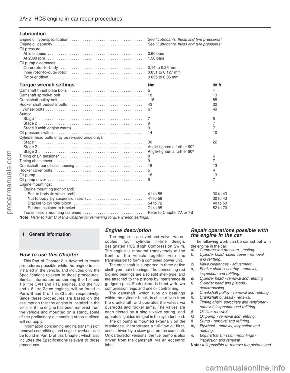
Lubrication
Engine oil type/specification . . . . . . . . . . . . . . . . . . . . . . . . . . . . . . . . . . See “Lubricants, fluids and tyre pressures”
Engine oil capacity . . . . . . . . . . . . . . . . . . . . . . . . . . . . . . . . . . . .\
. . . . . See “Lubricants, fluids and tyre pressures”
Oil pressure: At idle speed . . . . . . . . . . . . . . . . . . . . . . . . . . . . . . . . . . . .\
. . . . . . . . 0.60 barsAt 2000 rpm . . . . . . . . . . . . . . . . . . . . . . . . . . . . . . . . . . . .\
. . . . . . . . 1.50 bars
Oil pump clearances: Outer rotor-to-body . . . . . . . . . . . . . . . . . . . . . . . . . . . . . . . . . . . .\
. . 0.14 to 0.26 mm
Inner rotor-to-outer rotor . . . . . . . . . . . . . . . . . . . . . . . . . . . . . . . . . . 0.051 to 0.127 mm
Rotor endfloat . . . . . . . . . . . . . . . . . . . . . . . . . . . . . . . . . . . .\
. . . . . . . 0.025 to 0.06 mm
Torque wrench settingsNm lbf ft
Camshaft thrust plate bolts . . . . . . . . . . . . . . . . . . . . . . . . . . . . . . . . . . 5 4
Camshaft sprocket bolt . . . . . . . . . . . . . . . . . . . . . . . . . . . . . . . . . . . .\
. 1813
Crankshaft pulley bolt . . . . . . . . . . . . . . . . . . . . . . . . . . . . . . . . . . . .\
. . . 115 85
Rocker shaft pedestal bolts . . . . . . . . . . . . . . . . . . . . . . . . . . . . . . . . . . 4332
Flywheel bolts . . . . . . . . . . . . . . . . . . . . . . . . . . . . . . . . . . . .\
. . . . . . . . . 6749
Sump: Stage 1 . . . . . . . . . . . . . . . . . . . . . . . . . . . . . . . . . . . .\
. . . . . . . . . . . . 7 5
Stage 2 . . . . . . . . . . . . . . . . . . . . . . . . . . . . . . . . . . . .\
. . . . . . . . . . . . 9 7
Stage 3 (with engine warm) . . . . . . . . . . . . . . . . . . . . . . . . . . . . . . . . 9 7
Oil pressure switch . . . . . . . . . . . . . . . . . . . . . . . . . . . . . . . . . . . .\
. . . . . 1410
Cylinder head bolts (may be re-used once only): Stage 1 . . . . . . . . . . . . . . . . . . . . . . . . . . . . . . . . . . . .\
. . . . . . . . . . . . 3022
Stage 2 . . . . . . . . . . . . . . . . . . . . . . . . . . . . . . . . . . . .\
. . . . . . . . . . . . Angle-tighten a further 90º
Stage 3 . . . . . . . . . . . . . . . . . . . . . . . . . . . . . . . . . . . .\
. . . . . . . . . . . . Angle-tighten a further 90º
Timing chain tensioner . . . . . . . . . . . . . . . . . . . . . . . . . . . . . . . . . . . .\
. . 8 6
Timing chain cover . . . . . . . . . . . . . . . . . . . . . . . . . . . . . . . . . . . .\
. . . . . 9 7
Crankshaft rear oil seal housing . . . . . . . . . . . . . . . . . . . . . . . . . . . . . . . 1813
Rocker cover bolts . . . . . . . . . . . . . . . . . . . . . . . . . . . . . . . . . . . .\
. . . . . 5 4
Oil pump . . . . . . . . . . . . . . . . . . . . . . . . . . . . . . . . . . . .\
. . . . . . . . . . . . . 1813
Oil pump cover . . . . . . . . . . . . . . . . . . . . . . . . . . . . . . . . . . . .\
. . . . . . . . 9 7
Engine mountings: Engine mounting (right-hand):Bolt to body (in wheel arch) . . . . . . . . . . . . . . . . . . . . . . . . . . . . . . 41 to 58 30 to 43
Nut to body (by suspension strut) . . . . . . . . . . . . . . . . . . . . . . . . . . 41 to 58 30 to 43
Bracket to cylinder block . . . . . . . . . . . . . . . . . . . . . . . . . . . . . . . . 54 to 72 40 to 53
Rubber insulator to bracket . . . . . . . . . . . . . . . . . . . . . . . . . . . . . . 71 to 95 52 to 70
Transmission mounting fasteners . . . . . . . . . . . . . . . . . . . . . . . . . . . . Refer to Chapter 7A or 7B
Note: Refer to Part D of this Chapter for remaining torque wrench settings.
2A•2 HCS engine in-car repair procedures
1595Ford Fiesta Remake
1 General information
How to use this Chapter
This Part of Chapter 2 is devoted to repair
procedures possible while the engine is still
installed in the vehicle, and includes only the
Specifications relevant to those procedures.
Similar information concerning the 1.4 and
1.6 litre CVH and PTE engines, and the 1.6
and 1.8 litre Zetec engines, will be found in
Parts B and C of this Chapter respectively.
Since these procedures are based on the
assumption that the engine is installed in the
vehicle, if the engine has been removed from
the vehicle and mounted on a stand, some
of the preliminary dismantling steps outlined
will not apply. Information concerning engine/transmission
removal and refitting, and engine overhaul, can
be found in Part D of this Chapter, which also
includes the Specifications relevant to those
procedures.
Engine description
The engine is an overhead valve, water-
cooled, four cylinder in-line design,
designated HCS (High Compression Swirl).
The engine is mounted transversely at the
front of the vehicle together with the
transmission to form a combined power unit. The crankshaft is supported in three or five
shell-type main bearings. The connecting rod
big-end bearings are also split shell-type, and
are attached to the pistons by interference-fit
gudgeon pins. Each piston is fitted with two
compression rings and one oil control ring. The camshaft, which runs on bearings
within the cylinder block, is chain-driven from
the crankshaft, and operates the valves via
pushrods and rocker arms. The valves are
each closed by a single valve spring, and
operate in guides integral in the cylinder head. The oil pump is mounted externally on the
crankcase, incorporates a full-flow oil filter,
and is driven by a skew gear on the camshaft.
On carburettor versions, the fuel pump is also
driven from the camshaft, via an eccentric
lobe.
Repair operations possible with
the engine in the car
The following work can be carried out with
the engine in the car:
a) Compression pressure - testing.
b) Cylinder head rocker cover - removal
and refitting.
c) Valve clearances - adjustment.
d) Rocker shaft assembly - removal,
inspection and refitting.
e) Cylinder head - removal and refitting
f) Cylinder head and pistons - decarbonising.
g) Crankshaft pulley - removal and refitting.
h) Crankshaft oil seals - renewal.
i) Timing chain, sprockets and tensioner -
removal, inspection and refitting.
j) Oil filter renewal.
k) Oil pump - removal and refitting.
l) Sump - removal and refitting.
m) Flywheel - removal, inspection and
refitting.
n) Engine/transmission mountings -
inspection and renewal.
Note: It is possible to remove the pistons and
procarmanuals.com
http://vnx.su
Page 32 of 296
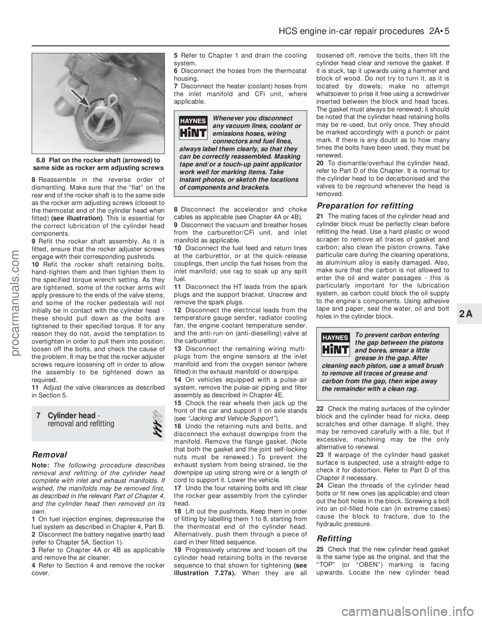
8Reassemble in the reverse order of
dismantling. Make sure that the “flat” on the
rear end of the rocker shaft is to the same side
as the rocker arm adjusting screws (closest to
the thermostat end of the cylinder head when
fitted) (see illustration) . This is essential for
the correct lubrication of the cylinder head
components.
9 Refit the rocker shaft assembly. As it is
fitted, ensure that the rocker adjuster screws
engage with their corresponding pushrods.
10 Refit the rocker shaft retaining bolts,
hand-tighten them and then tighten them to
the specified torque wrench setting. As they
are tightened, some of the rocker arms will
apply pressure to the ends of the valve stems,
and some of the rocker pedestals will not
initially be in contact with the cylinder head -
these should pull down as the bolts are
tightened to their specified torque. If for any
reason they do not, avoid the temptation to
overtighten in order to pull them into position;
loosen off the bolts, and check the cause of
the problem. It may be that the rocker adjuster
screws require loosening off in order to allow
the assembly to be tightened down as
required.
11 Adjust the valve clearances as described
in Section 5.
7 Cylinder head -
removal and refitting
3
Removal
Note: The following procedure describes
removal and refitting of the cylinder head
complete with inlet and exhaust manifolds. If
wished, the manifolds may be removed first,
as described in the relevant Part of Chapter 4,
and the cylinder head then removed on its
own.
1 On fuel injection engines, depressurise the
fuel system as described in Chapter 4, Part B.
2 Disconnect the battery negative (earth) lead
(refer to Chapter 5A, Section 1).
3 Refer to Chapter 4A or 4B as applicable
and remove the air cleaner.
4 Refer to Section 4 and remove the rocker
cover. 5
Refer to Chapter 1 and drain the cooling
system.
6 Disconnect the hoses from the thermostat
housing.
7 Disconnect the heater (coolant) hoses from
the inlet manifold and CFi unit, where
applicable.
8 Disconnect the accelerator and choke
cables as applicable (see Chapter 4A or 4B).
9 Disconnect the vacuum and breather hoses
from the carburettor/CFi unit, and inlet
manifold as applicable.
10 Disconnect the fuel feed and return lines
at the carburettor, or at the quick-release
couplings, then unclip the fuel hoses from the
inlet manifold; use rag to soak up any spilt
fuel.
11 Disconnect the HT leads from the spark
plugs and the support bracket. Unscrew and
remove the spark plugs.
12 Disconnect the electrical leads from the
temperature gauge sender, radiator cooling
fan, the engine coolant temperature sender,
and the anti-run-on (anti-dieselling) valve at
the carburettor.
13 Disconnect the remaining wiring multi-
plugs from the engine sensors at the inlet
manifold and from the oxygen sensor (where
fitted) in the exhaust manifold or downpipe.
14 On vehicles equipped with a pulse-air
system, remove the pulse-air piping and filter
assembly as described in Chapter 4E.
15 Chock the rear wheels then jack up the
front of the car and support it on axle stands
(see “Jacking and Vehicle Support” ).
16 Undo the retaining nuts and bolts, and
disconnect the exhaust downpipe from the
manifold. Remove the flange gasket. (Note
that both the gasket and the joint self-locking
nuts must be renewed.) To prevent the
exhaust system from being strained, tie the
downpipe up using strong wire or a length of
cord to support it. Lower the vehicle.
17 Undo the four retaining bolts and lift clear
the rocker gear assembly from the cylinder
head.
18 Lift out the pushrods. Keep them in order
of fitting by labelling them 1 to 8, starting from
the thermostat end of the cylinder head.
Alternatively, push them through a piece of
card in their fitted sequence.
19 Progressively unscrew and loosen off the
cylinder head retaining bolts in the reverse
sequence to that shown for tightening (see
illustration 7.27a). When they are all loosened off, remove the bolts, then lift the
cylinder head clear and remove the gasket. If
it is stuck, tap it upwards using a hammer and
block of wood. Do not try to turn it, as it is
located by dowels; make no attempt
whatsoever to prise it free using a screwdriver
inserted between the block and head faces.
The gasket must always be renewed; it should
be noted that the cylinder head retaining bolts
may be re-used, but only once. They should
be marked accordingly with a punch or paint
mark. If there is any doubt as to how many
times the bolts have been used, they must be
renewed.
20
To dismantle/overhaul the cylinder head,
refer to Part D of this Chapter. It is normal for
the cylinder head to be decarbonised and the
valves to be reground whenever the head is
removed.
Preparation for refitting
21 The mating faces of the cylinder head and
cylinder block must be perfectly clean before
refitting the head. Use a hard plastic or wood
scraper to remove all traces of gasket and
carbon; also clean the piston crowns. Take
particular care during the cleaning operations,
as aluminium alloy is easily damaged. Also,
make sure that the carbon is not allowed to
enter the oil and water passages - this is
particularly important for the lubrication
system, as carbon could block the oil supply
to the engine’s components. Using adhesive
tape and paper, seal the water, oil and bolt
holes in the cylinder block.
22 Check the mating surfaces of the cylinder
block and the cylinder head for nicks, deep
scratches and other damage. If slight, they
may be removed carefully with a file, but if
excessive, machining may be the only
alternative to renewal.
23 If warpage of the cylinder head gasket
surface is suspected, use a straight-edge to
check it for distortion. Refer to Part D of this
Chapter if necessary.
24 Clean the threads of the cylinder head
bolts or fit new ones (as applicable) and clean
out the bolt holes in the block. Screwing a bolt
into an oil-filled hole can (in extreme cases)
cause the block to fracture, due to the
hydraulic pressure.
Refitting
25 Check that the new cylinder head gasket
is the same type as the original, and that the
“TOP” (or “OBEN”) marking is facing
upwards. Locate the new cylinder head
HCS engine in-car repair procedures 2A•5
6.8 Flat on the rocker shaft (arrowed) to
same side as rocker arm adjusting screws
2A
1595Ford Fiesta Remake
Whenever you disconnect
any vacuum lines, coolant or
emissions hoses, wiring
connectors and fuel lines,
always label them clearly, so that they
can be correctly reassembled. Masking
tape and/or a touch-up paint applicator
work well for marking items. Take
instant photos, or sketch the locations
of components and brackets.
To prevent carbon entering
the gap between the pistons
and bores, smear a little
grease in the gap. After
cleaning each piston, use a small brush
to remove all traces of grease and
carbon from the gap, then wipe away
the remainder with a clean rag.
procarmanuals.com
http://vnx.su
Page 40 of 296

2B
1595Ford Fiesta Remake
General
Engine type . . . . . . . . . . . . . . . . . . . . . . . . . . . . . . . . . . . .\
. . . . . . . . . . . Four-cylinder, in-line overhead camshaft
Engine code:1.4 litre CVH engine: Carburettor models . . . . . . . . . . . . . . . . . . . . . . . . . . . . . . . . . . . .\
. FUF or FUG
CFi fuel injection models . . . . . . . . . . . . . . . . . . . . . . . . . . . . . . . . . F6E
1.4 litre PTE engine . . . . . . . . . . . . . . . . . . . . . . . . . . . . . . . . . . . .\
. . . F4A
1.6 litre CVH engine: Carburettor models . . . . . . . . . . . . . . . . . . . . . . . . . . . . . . . . . . . .\
. LUH
EFi fuel injection models . . . . . . . . . . . . . . . . . . . . . . . . . . . . . . . . . LJC or LJD
Turbo models . . . . . . . . . . . . . . . . . . . . . . . . . . . . . . . . . . . .\
. . . . . LHA
Capacity:
1.4 litre CVH and PTE engines . . . . . . . . . . . . . . . . . . . . . . . . . . . . . . 1392 cc
1.6 litre CVH engine . . . . . . . . . . . . . . . . . . . . . . . . . . . . . . . . . . . .\
. . 1596 cc
Bore:
1.4 litre CVH and PTE engines . . . . . . . . . . . . . . . . . . . . . . . . . . . . . . 77.24 mm
1.6 litre CVH engine . . . . . . . . . . . . . . . . . . . . . . . . . . . . . . . . . . . .\
. . 79.96 mm
Stroke:
1.4 litre CVH and PTE engines . . . . . . . . . . . . . . . . . . . . . . . . . . . . . . 74.30 mm
1.6 litre CVH engine . . . . . . . . . . . . . . . . . . . . . . . . . . . . . . . . . . . .\
. . 79.52 mm
Compression ratio:
1.4 litre CVH carburettor engine . . . . . . . . . . . . . . . . . . . . . . . . . . . . . 9.5:1
1.4 litre CVH CFi fuel injection engine . . . . . . . . . . . . . . . . . . . . . . . . 8.5:1
1.4 litre PTE engine . . . . . . . . . . . . . . . . . . . . . . . . . . . . . . . . . . . .\
. . . 9.5:1
1.6 litre CVH engine: Carburettor models . . . . . . . . . . . . . . . . . . . . . . . . . . . . . . . . . . . .\
. 9.5:1
EFi fuel injection models . . . . . . . . . . . . . . . . . . . . . . . . . . . . . . . . . 9.75:1
Turbo models . . . . . . . . . . . . . . . . . . . . . . . . . . . . . . . . . . . .\
. . . . . 8.0:1
Firing order . . . . . . . . . . . . . . . . . . . . . . . . . . . . . . . . . . . .\
. . . . . . . . . . . 1-3-4-2 (No 1 cylinder at timing belt end)
Direction of crankshaft rotation . . . . . . . . . . . . . . . . . . . . . . . . . . . . . . . Clockwise (seen from right-hand side of vehicle)
Chapter 2 Part B:
CVH and PTE engine in-car repair procedures
Auxiliary drivebelt check and renewal . . . . . . . . . . . . . . .See Chapter 1
Camshaft oil seal - renewal . . . . . . . . . . . . . . . . . . . . . . . . . . . . . . . . 10
Camshaft, rocker arms and tappets - removal, inspection and refitting . . . . . . . . . . . . . . . . . . . . . . . . . . . . . . . . . . . .\
. . . . . . 11
Compression test - description and interpretation . . . . . . . . . . . . . . 2
Crankshaft oil seals - renewal . . . . . . . . . . . . . . . . . . . . . . . . . . . . . . 16
Crankshaft pulley - removal and refitting . . . . . . . . . . . . . . . . . . . . . 6
Cylinder head - removal and refitting . . . . . . . . . . . . . . . . . . . . . . . . 12
Cylinder head rocker cover - removal and refitting . . . . . . . . . . . . . . 4
Engine oil and filter renewal . . . . . . . . . . . . . . . . . . . . . . .See Chapter 1
Engine oil level check . . . . . . . . . . . . . . . . . . . . . .See
“Weekly Checks”
Engine/transmission mountings - renewal . . . . . . . . . . . . . . . . . . . . 17 Flywheel/driveplate - removal, inspection and refitting . . . . . . . . . . 18
General information . . . . . . . . . . . . . . . . . . . . . . . . . . . . . . . . . . . .\
. . 1
Oil pump - dismantling, inspection and reassembly . . . . . . . . . . . . . 15
Oil pump - removal and refitting . . . . . . . . . . . . . . . . . . . . . . . . . . . . 14
Sump - removal and refitting . . . . . . . . . . . . . . . . . . . . . . . . . . . . . . . 13
Timing belt - removal, refitting and adjustment . . . . . . . . . . . . . . . . 8
Timing belt covers - removal and refitting . . . . . . . . . . . . . . . . . . . . . 7
Timing belt tensioner and sprockets - removal, inspection
and refitting . . . . . . . . . . . . . . . . . . . . . . . . . . . . . . . . . . . .\
. . . . . . 9
Top Dead Centre (TDC) for No 1 piston - locating . . . . . . . . . . . . . . 3
Valve clearances - general information . . . . . . . . . . . . . . . . . . . . . . . 5
2B•1
Specifications Contents
Easy, suitable for
novice with little
experience Fairly easy,
suitable
for beginner with
some experience Fairly difficult,
suitable for competent
DIY mechanic
Difficult,
suitable for
experienced DIY
mechanic Very difficult,
suitable for expert DIY
or professional
Degrees of difficulty
54321
procarmanuals.com
http://vnx.su
Page 64 of 296
5Disconnect the accelerator cable from the
throttle linkage as described in Chapter 4D.
Secure the cable clear of the engine/
transmission.
6 Remove the auxiliary drivebelt (see Chap-
ter 1).
7 Remove the three screws securing the
wiring “rail” to the rear of the manifold.
Releasing its wire clip, unplug the large
electrical connector (next to the fuel pressure
regulator) to disconnect the engine wiring from
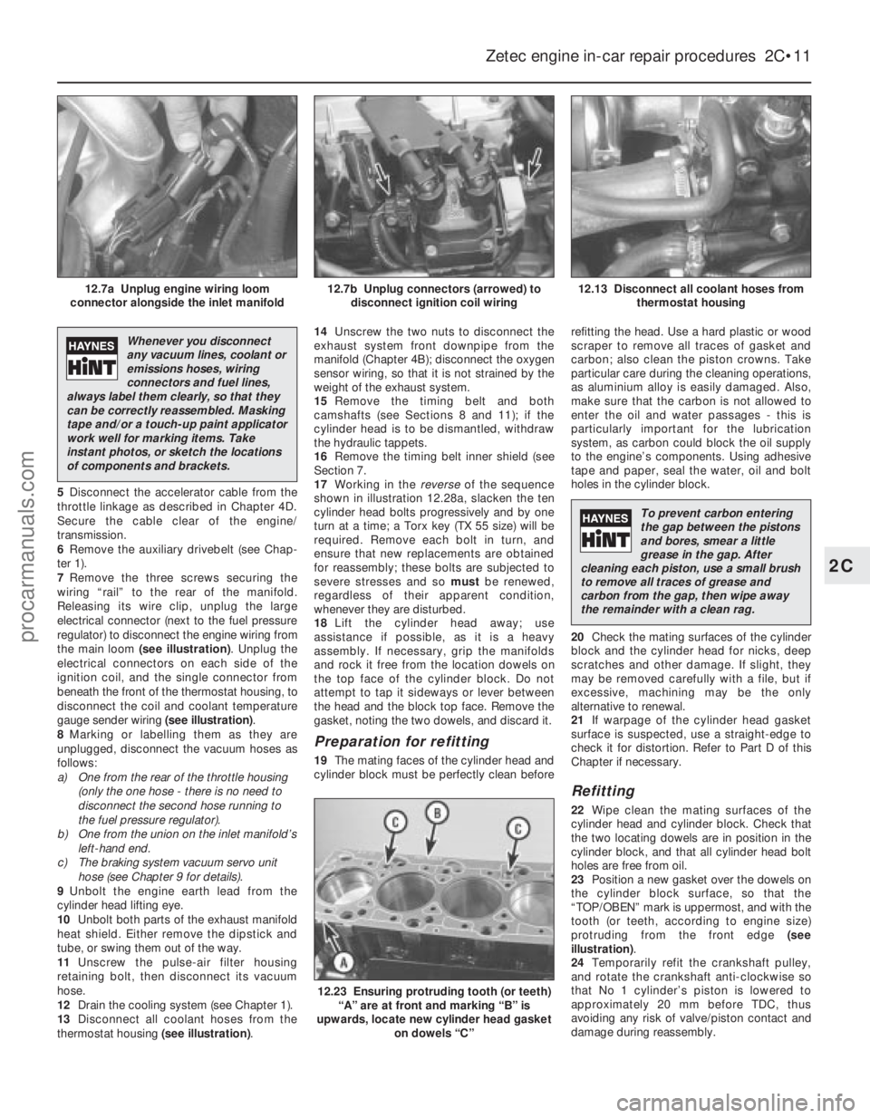
the main loom (see illustration) . Unplug the
electrical connectors on each side of the
ignition coil, and the single connector from
beneath the front of the thermostat housing, to
disconnect the coil and coolant temperature
gauge sender wiring (see illustration).
8 Marking or labelling them as they are
unplugged, disconnect the vacuum hoses as
follows:
a) One from the rear of the throttle housing
(only the one hose - there is no need to
disconnect the second hose running to
the fuel pressure regulator).
b) One from the union on the inlet manifold’s
left-hand end.
c) The braking system vacuum servo unit hose (see Chapter 9 for details).
9 Unbolt the engine earth lead from the
cylinder head lifting eye.
10 Unbolt both parts of the exhaust manifold
heat shield. Either remove the dipstick and
tube, or swing them out of the way.
11 Unscrew the pulse-air filter housing
retaining bolt, then disconnect its vacuum
hose.
12 Drain the cooling system (see Chapter 1).
13 Disconnect all coolant hoses from the
thermostat housing (see illustration).14
Unscrew the two nuts to disconnect the
exhaust system front downpipe from the
manifold (Chapter 4B); disconnect the oxygen
sensor wiring, so that it is not strained by the
weight of the exhaust system.
15 Remove the timing belt and both
camshafts (see Sections 8 and 11); if the
cylinder head is to be dismantled, withdraw
the hydraulic tappets.
16 Remove the timing belt inner shield (see
Section 7.
17 Working in the reverseof the sequence
shown in illustration 12.28a, slacken the ten
cylinder head bolts progressively and by one
turn at a time; a Torx key (TX 55 size) will be
required. Remove each bolt in turn, and
ensure that new replacements are obtained
for reassembly; these bolts are subjected to
severe stresses and so mustbe renewed,
regardless of their apparent condition,
whenever they are disturbed.
18 Lift the cylinder head away; use
assistance if possible, as it is a heavy
assembly. If necessary, grip the manifolds
and rock it free from the location dowels on
the top face of the cylinder block. Do not
attempt to tap it sideways or lever between
the head and the block top face. Remove the
gasket, noting the two dowels, and discard it.
Preparation for refitting
19 The mating faces of the cylinder head and
cylinder block must be perfectly clean before refitting the head. Use a hard plastic or wood
scraper to remove all traces of gasket and
carbon; also clean the piston crowns. Take
particular care during the cleaning operations,
as aluminium alloy is easily damaged. Also,
make sure that the carbon is not allowed to
enter the oil and water passages - this is
particularly important for the lubrication
system, as carbon could block the oil supply
to the engine’s components. Using adhesive
tape and paper, seal the water, oil and bolt
holes in the cylinder block.
20
Check the mating surfaces of the cylinder
block and the cylinder head for nicks, deep
scratches and other damage. If slight, they
may be removed carefully with a file, but if
excessive, machining may be the only
alternative to renewal.
21 If warpage of the cylinder head gasket
surface is suspected, use a straight-edge to
check it for distortion. Refer to Part D of this
Chapter if necessary.
Refitting
22 Wipe clean the mating surfaces of the
cylinder head and cylinder block. Check that
the two locating dowels are in position in the
cylinder block, and that all cylinder head bolt
holes are free from oil.
23 Position a new gasket over the dowels on
the cylinder block surface, so that the
“TOP/OBEN” mark is uppermost, and with the
tooth (or teeth, according to engine size)
protruding from the front edge (see
illustration) .
24 Temporarily refit the crankshaft pulley,
and rotate the crankshaft anti-clockwise so
that No 1 cylinder’s piston is lowered to
approximately 20 mm before TDC, thus
avoiding any risk of valve/piston contact and
damage during reassembly.
Zetec engine in-car repair procedures 2C•11
12.13 Disconnect all coolant hoses from thermostat housing12.7b Unplug connectors (arrowed) todisconnect ignition coil wiring12.7a Unplug engine wiring loom
connector alongside the inlet manifold
12.23 Ensuring protruding tooth (or teeth) “A” are at front and marking “B” is
upwards, locate new cylinder head gasket on dowels “C”
2C
1595Ford Fiesta Remake
Whenever you disconnect
any vacuum lines, coolant or
emissions hoses, wiring
connectors and fuel lines,
always label them clearly, so that they
can be correctly reassembled. Masking
tape and/or a touch-up paint applicator
work well for marking items. Take
instant photos, or sketch the locations
of components and brackets.
To prevent carbon entering
the gap between the pistons
and bores, smear a little
grease in the gap. After
cleaning each piston, use a small brush
to remove all traces of grease and
carbon from the gap, then wipe away
the remainder with a clean rag.
procarmanuals.com
http://vnx.su
Page 79 of 296
25Unscrew the retaining bolt, and detach
the shift rod stabiliser from the transmission.
As it is detached, note the washer located
between the stabiliser and the transmission.
Tie the stabiliser and the shift rod up out of
the way.
Automatic transmission models
26 Unclip and detach the wiring connector
from the starter inhibitor switch (on the
transmission housing).
27 Referring to the relevant Part of Chapter 4
for details, unhook the accelerator (cam plate)
cable from the carburettor or fuel injection unit
(as applicable) at the transmission end of
the cable. Undo the retaining bolt and
detach the cable sheath bracket from the
transmission. Detach the cam plate cable
from the link.
28 Undo the two nuts from the selector cable
bracket which connects it to the lever on the
selector shaft. Disconnect the yoke from the
lever on the selector shaft and the cable from
the lever.
29 Unscrew the union nuts, and disconnect
the oil cooler feed and return pipes from the
transmission. Allow for a certain amount of
spillage, and plug the connections to prevent
the ingress of dirt.
All models
30 Unscrew the retaining nut and withdraw
the Torx-type clamp bolt securing the lower
suspension arm to the spindle carrier on each
side.
31 Refer to Chapter 10 for details, and
detach the right-hand and left-hand track rod
end balljoints from the spindle carriers.
32 On vehicles fitted with the anti-lock
braking system, refer to Chapter 9 and release
the right-hand modulator from its mounting
bracket without disconnecting the rigid brake
pipes or return hose. Tie the modulator
securely to the bulkhead. Additionally, undo
the three bolts securing the modulator
bracket.
33 Insert a suitable lever between the right-
hand driveshaft inner joint and the
transmission housing, and prise free the
driveshaft from the transmission; be prepared
for oil spillage from the transmission case
through the vacated driveshaft aperture. As it
is being prised free, simultaneously pull the
roadwheel outwards on that side, to enable
the driveshaft inboard end to separate
from the transmission. Once it is free,
suspend and support the driveshaft from the
steering gear, to prevent unnecessary strain
being placed on the driveshaft joints.
34 Insert a suitable plastic plug (or if
available, an old driveshaft joint), into the
transmission driveshaft aperture, to
immobilise the gears of the differential unit.
35 Proceed as described above in
paragraphs 33 and 34, and disconnect the
left-hand driveshaft from the transmission.
36 Connect a suitable lift hoist and sling to
the engine, connecting to the lifting eyes. When securely connected, take the weight of
the engine/transmission unit so that the
tension is relieved from the mountings.
37
Undo the retaining bolts and nuts and
detach the right-hand engine mounting from
the vehicle body.
38 Undo the four bolts securing the
transmission bearer to the underside of the
vehicle body. The transmission bearer is
removed with the engine/transmission
assembly.
39 Unscrew the three retaining bolts, and
remove the auxiliary drivebelt cover from
under the crankshaft pulley.
40 The engine/transmission unit should now
be ready for removal from the vehicle. Check
that all of the associated connections and
fittings are disconnected from the engine and
transmission, and positioned out of the way.
41 Enlist the aid of an assistant to help
steady and guide the power unit down
through the engine compartment as it is
removed. If available, position a suitable
engine trolley or crawler board under the
engine/transmission so that when lowered,
the power unit can be withdrawn from the
front end of the vehicle, and then moved to
the area where it is to be cleaned and
dismantled. On automatic transmission
models, particular care must be taken not to
damage the transmission fluid pan (sump)
during the removal and subsequent refitting
processes.
42 Carefully lower the engine and
transmission unit, ensuring that no fittings
become snagged. Detach the hoist and
remove the power unit from under the vehicle.
43 Referring to the relevant Part of Chapter 7,
separate the transmission from the engine.
44 While the engine/transmission is removed,
check the mountings; renew them if they are
worn or damaged. Similarly, check the
condition of all coolant and vacuum hoses
and pipes (see Chapter 1). Components that
are normally hidden can now be checked
properly, and should be renewed if there is
any doubt at all about their condition. Where
the vehicle is fitted with manual transmission,
take the opportunity to inspect the clutch
components (see Chapter 6). It is regarded by
many as good working practice to renew the
clutch assembly as a matter of course,
whenever major engine overhaul work is
carried out. Check also the condition of all
components (such as the transmission oil
seals) disturbed on removal, and renew any
that are damaged or worn.
Refitting
45 Refitting is a reversal of removal, however
note the following additional points:
a) Refer to the applicable Chapters and Sections as for removal.
b) Fit new spring clips to the grooves in the
inboard end of the right- and left-hand
driveshaft joints. Lubricate the splines
with transmission oil prior to fitting. c) Renew the exhaust flange gasket when
reconnecting the exhaust. Ensure that all
wires are routed clear of the exhaust
system and, on catalytic converter
models, ensure that the heat shields are
securely and correctly fitted.
d) Ensure that all earth lead connections are
clean and securely made.
e) Tighten all nuts and bolts to the specified torque.
f) Fit a new oil filter, and refill the engine and transmission with oil, with reference to
Chapter 1.
g) Refill the cooling system with reference to Chapter 1.
h) Refit the alternator and starter motor with reference to Chapter 5A.
i) Where applicable, refit the power steering pump with reference to Chapter 10.
46 When engine and transmission refitting is
complete, refer to the procedures described
in Section 19 before restarting the engine.
5 Engine/transmission -
removal and refitting
(Zetec engines)
3
Warning: Petrol is extremely
flammable, so take extra
precautions when disconnecting
any part of the fuel system.
Don’t smoke, or allow naked flames or
bare light bulbs, in or near the work area,
and don’t work in a garage where a
natural-gas appliance (such as a clothes
dryer or water heater) is installed. If you
spill petrol on your skin, rinse it off
immediately. Have a fire extinguisher rated
for petrol fires handy, and know how to
use it.
Note: Read through the entire Section, as well
as reading the advice in Section 2, before
beginning this procedure. The engine and
transmission are removed as a unit, lowered to
the ground and removed from underneath,
then separated outside the vehicle.
Removal
1 Park the vehicle on firm, level ground, apply
the handbrake firmly, and slacken the nuts
securing both front roadwheels.
2 Depressurise the fuel system as described
in Chapter 4D.
3 Disconnect the battery negative (earth) lead
(refer to Chapter 5A, Section 1).
4 Place protective covers on the wings, then
remove the bonnet (see Chapter 11).
5 Drain the cooling system and the engine oil
(see Chapter 1).
6 Remove the air inlet components and the
complete air cleaner assembly as described in
Chapter 4D.
7 Equalise the pressure in the fuel tank by
removing the filler cap, then release the fuel
feed and return quick-release couplings, and
pull the hoses off the fuel pipes. Plug or cap
all open fittings.
2D•10 Engine removal and overhaul procedures
1595Ford Fiesta Remakeprocarmanuals.com
http://vnx.su
Page 80 of 296
8Disconnect the accelerator cable from the
throttle linkage as described in Chapter 4D.
Secure the cable clear of the
engine/transmission.
9 Releasing its wire clip, unplug the wiring
connector from the power steering pressure
switch (where fitted), then disconnect the
earth cable from the engine lifting eye. Refit
the bolt after disconnecting the cable.
10 Marking or labelling all components as
they are disconnected, disconnect the
vacuum hoses as follows:
a) From the rear of the inlet manifold.
b) The braking system vacuum servo unit
hose - from the inlet manifold (see
Chapter 9 for details).
c) While you are there, trace the vacuum line
from the pulse-air filter housing, and
disconnect it from the pulse-air solenoid
valve.
d) Secure all these hoses so that they won’t
get damaged as the engine/transmission
is removed.
11 Unbolt the engine/transmission-to-body earth lead from the transmission
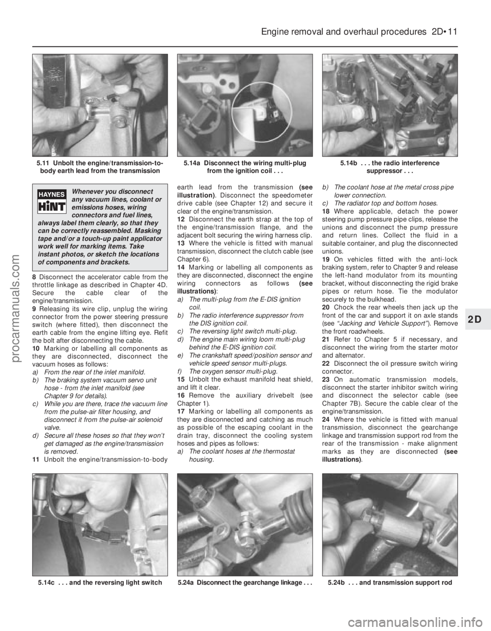
(see
illustration) . Disconnect the speedometer
drive cable (see Chapter 12) and secure it
clear of the engine/transmission.
12 Disconnect the earth strap at the top of
the engine/transmission flange, and the
adjacent bolt securing the wiring harness clip.
13 Where the vehicle is fitted with manual
transmission, disconnect the clutch cable (see
Chapter 6).
14 Marking or labelling all components as
they are disconnected, disconnect the engine
wiring connectors as follows (see
illustrations) :
a) The multi-plug from the E-DIS ignition
coil.
b) The radio interference suppressor from
the DIS ignition coil.
c) The reversing light switch multi-plug.
d) The engine main wiring loom multi-plug
behind the E-DIS ignition coil.
e) The crankshaft speed/position sensor and vehicle speed sensor multi-plugs.
f) The oxygen sensor multi-plug.
15 Unbolt the exhaust manifold heat shield,
and lift it clear.
16 Remove the auxiliary drivebelt (see
Chapter 1).
17 Marking or labelling all components as
they are disconnected and catching as much
as possible of the escaping coolant in the
drain tray, disconnect the cooling system
hoses and pipes as follows:
a) The coolant hoses at the thermostat housing. b)
The coolant hose at the metal cross pipe
lower connection.
c) The radiator top and bottom hoses.
18 Where applicable, detach the power
steering pump pressure pipe clips, release the
unions and disconnect the pump pressure
and return lines. Collect the fluid in a
suitable container, and plug the disconnected
unions.
19 On vehicles fitted with the anti-lock
braking system, refer to Chapter 9 and release
the left-hand modulator from its mounting
bracket, without disconnecting the rigid brake
pipes or return hose. Tie the modulator
securely to the bulkhead.
20 Chock the rear wheels then jack up the
front of the car and support it on axle stands
(see “Jacking and Vehicle Support” ). Remove
the front roadwheels.
21 Refer to Chapter 5 if necessary, and
disconnect the wiring from the starter motor
and alternator.
22 Disconnect the oil pressure switch wiring
connector.
23 On automatic transmission models,
disconnect the starter inhibitor switch wiring
and disconnect the selector cable (see
Chapter 7B). Secure the cable clear of the
engine/transmission.
24 Where the vehicle is fitted with manual
transmission, disconnect the gearchange
linkage and transmission support rod from the
rear of the transmission - make alignment
marks as they are disconnected (see
illustrations) .
Engine removal and overhaul procedures 2D•11
5.14b . . . the radio interference
suppressor . . .5.14a Disconnect the wiring multi-plugfrom the ignition coil . . .5.11 Unbolt the engine/transmission-to-body earth lead from the transmission
5.24b . . . and transmission support rod5.24a Disconnect the gearchange linkage . . .5.14c . . . and the reversing light switch
2D
1595Ford Fiesta Remake
Whenever you disconnect
any vacuum lines, coolant or
emissions hoses, wiring
connectors and fuel lines,
always label them clearly, so that they
can be correctly reassembled. Masking
tape and/or a touch-up paint applicator
work well for marking items. Take
instant photos, or sketch the locations
of components and brackets.
procarmanuals.com
http://vnx.su
Page 81 of 296
25On automatic transmission models, clean
around the unions, then disconnect the fluid
pipes from the transmission. Plug the
openings in the transmission and the pipe
unions after removal.
26 Refer to Chapter 10 and remove the front
suspension crossmember.
27 Unscrew the nuts to disconnect the
exhaust system front downpipe from the
manifold. Undo the nuts securing the catalytic
converter to the rear part of the exhaust
system, and remove the converter and
downpipe assembly.
28 On vehicles fitted with the anti-lock braking
system, refer to Chapter 9 and release the
right-hand modulator from its mounting
bracket without disconnecting the rigid brake
pipes or return hose. Tie the modulator
securely to the bulkhead. Additionally, undo
the three bolts securing the modulator bracket.
29 Disconnect both anti-roll bar links from
their respective suspension struts, and both
track rod end ball joints from their spindle
carriers (see Chapter 10).
30 Unscrew the retaining nut and withdraw
the Torx-type clamp bolt securing the lower
suspension arm to the spindle carrier on each
side.
31 Insert a suitable lever between the right-
hand driveshaft inner joint and the
transmission housing, and prise free the
driveshaft from the transmission; be prepared
for oil spillage from the transmission case
through the vacated driveshaft aperture. As it
is being prised free, simultaneously pull the
roadwheel outwards on that side to enable the
driveshaft inboard end to separate from the
transmission. Once it is free, suspend and
support the driveshaft from the steering gear,
to prevent unnecessary strain being placed on
the driveshaft joints.
32 Insert a suitable plastic plug (or if
available, an old driveshaft joint), into the
transmission driveshaft aperture, to
immobilise the gears of the differential unit.
33 Proceed as described above in
paragraphs 31 and 32, and disconnect the
left-hand driveshaft from the transmission.
34 Remove the oil filter, referring to Chapter 1
if necessary.
35 Connect a suitable lift hoist and sling to
the engine, connecting to the lift eyes. When
securely connected, take the weight of the
engine/transmission unit so that the tension is
relieved from the mountings.
36 Unbolt the engine rear right-hand
mounting from the body (one bolt in the wheel
arch, one nut in the engine compartment),
then unbolt the engine front right-hand
mounting from the alternator mounting
bracket. Unbolt the transmission bearer from
the underbody.
37 The engine/transmission unit should now
be hanging on the hoist only, with all
components which connect it to the rest of
the vehicle disconnected or removed, and
secured well clear of the unit. Make a final
check that this is the case. 38
Lower the engine/transmission to the
ground, and withdraw it from under the
vehicle.
39 Referring to the relevant Part of Chapter 7,
separate the transmission from the engine.
40 While the engine/transmission is removed,
check the mountings; renew them if they are
worn or damaged. Similarly, check the
condition of all coolant and vacuum hoses
and pipes (see Chapter 1); components that
are normally hidden can now be checked
properly, and should be renewed if there is
any doubt at all about their condition. Where
the vehicle is fitted with manual transmission,
take the opportunity to overhaul the clutch
components (see Chapter 6). It is regarded by
many as good working practice to renew the
clutch assembly as a matter of course,
whenever major engine overhaul work is
carried out. Check also the condition of all
components (such as the transmission oil
seals) disturbed on removal, and renew any
that are damaged or worn.
Refitting
41 Refitting is a reversal of removal, however
note the following additional points:
a) Refer to the applicable Chapters and Sections as for removal.
b) Fit new spring clips to the grooves in the
inboard end of the right- and left-hand
driveshaft joints. Lubricate the splines
with transmission oil prior to fitting.
c) Renew the exhaust flange gaskets when reconnecting the exhaust. Ensure that all
wires are routed clear of the exhaust
system, and that the heat shields are
securely and correctly fitted.
d) Ensure that all earth lead connections are
clean and securely made.
e) Tighten all nuts and bolts to the specified
torque.
f) Fit a new oil filter, and refill the engine and transmission with oil, with reference to
Chapter 1.
g) Refill the cooling system with reference to
Chapter 1.
h) Bleed the power steering system with reference to Chapter 10.
42 When engine and transmission refitting is
complete, refer to the procedures described
in Section 19 before restarting the engine.
6 Engine overhaul - preliminary information
It is much easier to dismantle and work on
the engine if it is mounted on a portable
engine stand. These stands can often be hired
from a tool hire shop. Before the engine is
mounted on a stand, the flywheel/driveplate
should be removed so that the stand bolts
can be tightened into the end of the cylinder
block/crankcase. If a stand is not available, it is possible to
dismantle the engine with it suitably supported on a sturdy, workbench or on the
floor. Be careful not to tip or drop the engine
when working without a stand.
If you intend to obtain a reconditioned
engine, all ancillaries must be removed first, to
be transferred to the replacement engine (just
as they will if you are doing a complete engine
overhaul yourself). These components include
the following:
a) Alternator/power steering pump and
mounting brackets.
b) DIS/E-DIS ignition coil unit (and mounting
bracket), distributor, HT leads and spark
plugs.
c) The thermostat and housing cover.
d) Carburettor/fuel injection system
components.
e) Inlet and exhaust manifolds.
f) Oil filter.
g) Fuel pump.
h) Engine mountings.
i) Flywheel/driveplate.
j) Water pump.
Note: When removing the external
components from the engine, pay close
attention to details that may be helpful or
important during refitting. Note the fitted
positions of gaskets, seals, washers, bolts and
other small items. If you are obtaining a “short” engine
(cylinder block/crankcase, crankshaft, pistons
and connecting rods all assembled), then the
cylinder head, timing chain/belt (together with
tensioner, tensioner and idler pulleys and
covers) sump and oil pump will have to be
removed also. If a complete overhaul is planned, the
engine can be dismantled in the order given
below, referring to Part A, B or C of this
Chapter unless otherwise stated.
a) Inlet and exhaust manifolds.
b) Timing chain/belt, tensioner and
sprockets.
c) Cylinder head.
d) Flywheel/driveplate.
e) Sump.
f) Oil pump.
g) Pistons (with connecting rods).
h) Crankshaft.
i) Camshaft and tappets (HCS engines).
7 Cylinder head - dismantling
4
Note:New and reconditioned cylinder heads
are available from the manufacturers, and from
engine overhaul specialists. Due to the fact
that some specialist tools are required for the
dismantling and inspection procedures, and
new components may not be readily available,
it may be more practical and economical for
the home mechanic to purchase a
reconditioned head, rather than to dismantle,
inspect and recondition the original head.
1 Remove the cylinder head as described in
Part A, B or C of this Chapter (as applicable).
2D•12 Engine removal and overhaul procedures
1595Ford Fiesta Remakeprocarmanuals.com
http://vnx.su